THE DESIGN OF DARKNESS CONTROLLED LIGHT SWITCH
CIRCUIT
MOHD HAZWAN BIN HAMZAH
This Report Is Submitted In Partial Fulfillment of Requirements for the Degree of Bachelor in Electrical Engineering
(Industrial Power)
Fakulti Kejuruteraan Elektrik Universiti Teknikal Malaysia (UTeM)
“I hereby declared that I have read through this report and found that it has comply the
partial fulfillment for awarding the degree of Bachelor of Electrical Engineering
(Industrial Power)”
Signature : ……….
Supervisor‟s Name : P. M. Dr. Musse Mohamud Ahmed
“Saya akui bahawa saya telah membaca karya ini pada pandangan saya karya ini
adalah memadai dari skop dan kualiti untuk tujuan penanugerahan Ijazah Sarjana Muda Kejuruteraan Elektrik (Kuasa Industri).”
Signature : ……….
Supervisor‟s Name : P. M. Dr. Musse Mohamud Ahmed
ii
“I hereby declared that this report is a result of my own work except for the excepts that have been cited clearly in the references”
Signature : ………
Name : Mohd Hazwan Bin Hamzah Matrix Number : B010510168
iii
“Saya akui laporan ini adalah hasil kerja saya sendiri kecuali ringkasan dan petikan
yang tiap-tiap satunya saya jelaskan sumbernya.”
Tandatangan : ………
Nama : Mohd Hazwan Bin Hamzah No. Matrik : B010510168
iv
For my beloved father and mother
v
ACKNOWLEDGEMENTS
In the name of Allah, The Beneficent, The Merciful.
Alhamdulillah, all praise is to Allah that I have been able to complete my report
for my “Projek Sarjana Muda 2” that is The Designed of Darkness Controlled Light Switch.
vi
ABSTRACT
Most public buildings or industrial units need to be switched on at night and switched off at a specified time in the morning. The installation of „Darkness Controlled
vii
ABSTRAK
viii
CONTENTS
CHAPTER TITLE PAGE
TITLE i
ACKNOWLEDGEMENTS v
ABSTRACT vi
ABSTRAK vii
CONTENTS viii
LIST OF FIGURES xi
LIST OF TABLES xii
LIST OF ABBREVIATIONS xiii
LIST OF APPENDICES xii
1 INTRODUCTION 1.1 Project Overview 1
1.2 Project Objectives 2
1.3 Problem Statement 2
ix
1.5 Project Report Outline 3
2 LITERATUTE REVIEW / THEORIES
2.1 Introduction 5
2.2 Principals and Concepts of Darkness Controlled Light 5
2.2.1 Luminosity 6
2.3 Applications of Darkness Controlled Light Switch
Security Lighting 7 2.11 4060 14-Bit (÷16,384) Ripple Counter with Internal
x
4.3 Main Hardware Components 26 4.3.1 Light Dependent Resistor (LDR) 26
4.3.2 Battery 28
4.3.3 IC CD4060 and CD4040 29
4.3.4 Diode 32
5 RESULT AND ANALYSIS
5.1 Experimental Result 33
5.1.1 Variable Sensor Analysis 33
5.1.2 Rotary Switch Analysis 34
5.2 Discussion 37
6 CONCLUSION AND RECOMMENDATION
6.1 Conclusion 42
6.2 Recommendation 43
xi
LIST OF FIGURES
NO TITLE PAGE
Figure 2.1 AC and DC Circuit 8
Figure 2.2 Darkness Controlled Light Switch Circuit Diagram 10
Figure 2.3 Current Path through a Transistor 11
Figure 2.4 Transistor as a Switch 11
Figure 2.5 Protection diode 12
Figure 2.6 IC CD4040 13
Figure 2.7 IC CD4060 14
Figure 2.8 RC Oscillator 14
Figure 2.9 Dark Activated Switch Circuit 16
Figure 3.1 Project Planning Schedules 18
Figure 3.2 Project Methodology Flow Chart 20
xii
Figure 5.5 IC CD 4040 with no pin 8 and pin 16 38 Figure 5.6 Simulate the circuit without ICs CD4060 and CD4040 39 Figure 5.7 Simulate the circuit without ICs CD4060 and CD4040 39 Figure 5.8 Output Frequency at Q11 = 72.67Hz 40 Figure 5.9 Output Frequency at Q10 = 32.30Hz 40 Figure 5.10 Output Frequency at Q9 = 16.34Hz 41
LIST OF TABLES
NO TITLE PAGE
xiii
LIST OF ABBREVIATIONS
AC Alternating Current DC Direct Current
LDR Light Dependent Resistance PIC Programmable Interface Controller LUX Luminousity
LIST OF APPENDIX
NO TITLE PAGE
APPENDIX A Datasheet 45
APPENDIX B Project Planning 66
1
CHAPTER 1
INTRODUCTION
1.1 Project Overview
The focus of this project is to design and develop a Darkness Controlled Light Switch. 6V DC battery is used to supply the rest of the circuit. DC relay that switch a 240V AC mains circuit also is used 6V DC to operate. There is a circuit need to be built and the circuit is Darkness Controlled Light Switch circuit. The function of Darkness Controlled Light Switch is to be switched on in the dark and switched off in the bright.
2 switched off at a specified time in the morning. Control of lights can be done manually at the wall switch, but this way is not practical because some one has to switch on the light at the time night and switched off it again in the morning. By using the Darkness Controller Light Switch, the lights can be controlled automatically during the dark.
1.4 Scope of the Project
To study the darkness controlled light switch circuit To design the circuit
3
1.5 Project Report Outline
Generally this project report is divided into six chapters, where it consists: Chapter 1: Introduction that will be done are based on the objectives and scopes that been stated earlier.
Chapter 2 presents the literature review and theory background. In this chapter the theoretical and concepts of Darkness Controlled Light Switch will be explained. It is to provide the basic principals and concepts of darkness controlled light switch circuit. Studies on literature review helps in understanding the fundamental of darkness controlled light switch circuit concept.
Chapter 3 will discuss about the methodology that shall be adopted for this
project work which is basically defined in the planning process flow and principles that is essential guide to produce a well planned project. Besides, selected approach or methodology will describe the activities that might be done in every stage.
4
Chapter 5 will be discussed the results and analysis. Where the collected data from experimental work will be gathered before the analysis will be performed. The final sections from this chapter are the discussion for the gathered data.
Chapter 6 will conclude all the works which have been presented in the previous chapters and all the results of the project. This is followed by recommendations for the future study work.
5 identified and studied. The information is from the website, books, journals and articles. Besides that, this chapter also includes the difference between other darkness controller circuit and the design circuit.
2.2 Principals and Concepts of Darkness Controlled Light
Lighting includes both artificial light sources such as lamps from daylight. The main source of light during daytime in buildings is through the windows or skylights is often used as given its low cost. Lighting represents a major component of energy consumption, accounting for a significant part of all energy consumed worldwide. Artificial lighting is most commonly provided today by electric lights, but gas lighting, candles, or oil lamps were used in the past and still used in certain situations.
6
heats until it glows, or through gases until they become excited and produce light energy.
A typical lighting system is comprised of one or more of these light sources, called the lamps. Fluorescent, HID and low-pressure sodium lamps operate with ballast, a device that starts the lamp and regulates its operation. Lamps and ballasts in turn are part of the luminaire, or light fixture, which houses the system and includes other components that distribute the light in a controlled pattern. [7]
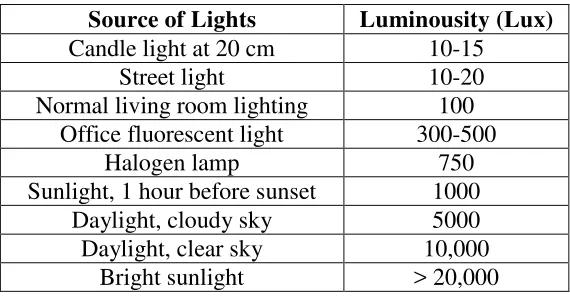
2.2.1 Luminosity
Light can be differing in luminosity, or brightness. A table lamp emits less light than a halogen lamp, but even a halogen source cannot be compared with bright sunlight, as far as luminosity is concerned. Luminosity depends on the amount of available light. It can be measured and recorded in a numeric value. Nowadays Lux is used to express the amount of luminosity. Table 2.1 below shows Luminousity (Lux) depends on the source of lights.
Table 2.1: Luminousity (Lux) Depends On the Source of Lights Source of Lights Luminousity (Lux)
Sunlight, 1 hour before sunset 1000 Daylight, cloudy sky 5000
7
2.3 Applications of Darkness Controlled Light Switch Security Lighting
Security lights are an additional safety measure homeowners can use to protect their property. Crime simply cannot occur as easily if there are no dark places for intruders to hide. Darkness controlled light switch can be used for security and eliminate wasted power consumption, waste energy, and waste money. These new lights do a better job of aiming light only where it is needed. The light will turn on during darkness and off during brightness. Darkness controlled light switch for security lighting can be installed at residential areas, walkways, shopping centers, malls, access roads, parking lots and other outdoor areas. [6]
2.4 Operation of Darkness Controlled Light Switch Circuit
Most public buildings or industrial units need to be switched on at night and switched off at a specified time in the morning. The installation of Darkness Controlled Light Switch Circuit can control the operation of buildings or industrial lights. A photocell, turns lights on as light levels drop (at dusk) and then turns them off again when light levels rise (at dawn). Dusk to dawn operation means that lights will be turned on an average of 12 hours each day. Darkness Controlled Light Switch Circuit could keep lights off and simply have them turn on automatically whenever the light level rise.
8
2.5 Basic Operations and Theory
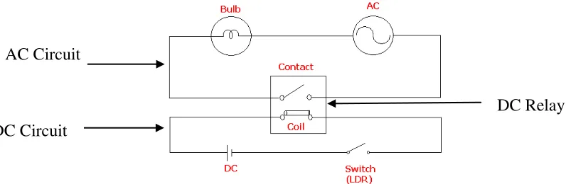
In this circuit, the light dependent resistance (LDR) is reacting as the switch. When there is no light falling on the LDR, the value of LDR can be as low as 80 ohm and the switch is in open condition. While the light is falling on the LDR, the value of LDR can increase to over 1M ohm and the switch is in close condition so the current is applied to a bulb causing it to light. Figure 2.1 consists of two separate circuits. One circuit is the DC part and the other is AC part.
DC relay is used to control an operation of AC circuit. When the switch is open, no current flows through the coil of the relay. As soon as the switch is closed, current start to flow through the coil causing a magnetic field to build up. This magnetic field causes the contacts of the relay to close. Hence, AC current flow through the bulb and the light of the bulb can be seen.
Figure 2.1: AC and DC Circuit DC Circuit
AC Circuit
9
2.6 Circuit Operations
The light sensor used is the photocell. In bright light, the resistance of the photocell can be as low as 80 ohm. In darkness, resistance increases to over 1 M ohm. Transistor T1 does not get sufficient forward bias current and is cut-off. This causes forward biasing of transistor T2 and, as a result, the power supply becomes available to the rest of the circuit.
IC1 (CD4060) functions as a square wave generator. The output waveform is initially low and goes high at 50 percent of time period at the output pin. The basic oscillator time period is given by the formula: T (time period) =2.3xC1xR2 sec. This basic clock is divided within this 14-stage binary counter. In this circuit the output of the 10th stage at pin 15 is used.
The output pulse period of IC1 is multiplied further by IC2 (CD4040), which is a 12-stage binary counter. Any one of the outputs (Q2 to Q12) may be selected using rotary switch S1. Q1 output of IC2 has been used for LED blinking to show that circuit is functioning.
The final output, which is initially at logic low, is fed to the transistor T3 which is thus cut-off. This results in forward biasing of transistor T4 which causes relay RL1 to be energised.