UNIVERSITI TEKNIKAL MALAYSIA MELAKA
DEVELOPMENT OF AN EXPERT SYSTEM
FOR WELDING PROCESS VERIFICATION
USING MS VISUAL BASIC
Thesis submitted in accordance with the partial requirements of the Universiti
Teknikal Malaysia Melaka for the Bachelor of Manufacturing Engineering
(Manufacturing Design)
By
Sharaynee a/p Krishnan
Metric Number: B050410026
Faculty of Manufacturing Engineering
APPROVAL
This thesis submitted to the senate of UTeM and has been accepted as partial
fulfilment of the requirements for the Bachelor of Manufacturing Engineering
(Manufacturing Design). The members of the supervisory committee are as follow:
……….
En Shajahan B. Maidin
Main Supervisor
DECLARATION
I hereby, declared this thesis entitled “Development of an Expert System for Welding
Process Verification using Ms Visual Basic” is the results of my own research except
as cited in references.
Signature : ……….
Author’s Name : ………
ABSTRACT
ABSTRAK
DEDICATION
“To my beloved parents, Mr Krishnan a/l Marimuthu and Mrs Devi Rani a/p Kuruppan, whom give me love and support …………..”
“To my family ………always believe in me………”
ACKNOWLEDGEMENT
I would like to thank Mr Shajahan Bin Maidin as my supervisor for giving full support, guidance, encouragement to develop this project successfully. Special thanks to Miss Zeratul Izzah and Mrs Azlianor for spending time to clear my doubts in programming.
I would like to thank my family and friends which give full support and stand beside me when I face problem.
TABLE OF CONTENT
List of Abbreviations, Symbols and Specialized Nomenclature……...….……....xi
List of Appendices……….…....xii
CHAPTER 1 INTRODUCTION 1.1 Background of the problem……...…………..……….…………1
1.2 Problem Statement………..……….………….2
2.2.1.3 Flux Core Metal Arc Welding………...8
2.3.1 Types of Material...……...………..…….……15
2.3.2 Location of Work...15
2.3.3 Types of Joint………...……...…….17
2.3.4 Size of Material………...……….17
2.4 Comparison of Welding Process………...……….18
CHAPTER 3 METHODOLOGY 3.1 Introduction………..…...30
3.2 Flow chart………...…30
3.3 Project Details………….………..……..…..…..………32
3.4 Conclusion………..………34
CHAPTER 4 DESIGN AND DEVELOPMENT OF PROGRAMMING 4.1 Introduction……….…35
4.2 Visual Basic Programming…...……….……….35
4.2.1 Analyze and Define the Problem ……….……...…...35
4.2.2 Designing the Visual Interface………38
4.2.3.1 Object Properties………….………40
4.2.6 Test and Edit the Program………...…………...…59
4.3 Building Database in Access………..………59
CHAPTER 5 PROGRAMMING RESULT 5.1 Introduction………..………….….60
6.7 Access Data from Microsoft Access database………80
CHAPTER 7 CONCLUSION & RECOMMENDATIONS 7.1 Conclusion……….………....….81
7.2 Recommendation………82
LIST OF FIGURE
2.1 Classification of Welding and Allied Process (AWS) 4 2.2 Shielded Metal Arc Welding Process 6 2.3 Gas Metal Arc Welding Process 7
2.4 GMAW Welding 7
2.5 FCAW Welding Process 8 2.6 GTAW Welding Process 9 2.7 Brazing a Butt Joint 10 2.8 Machining Tool Bit Showing How the Carbide Insert is Brazed to
the Tool Bit Body Using Pre placed Brazing Filler Metal Shims.
11 2.9 Soldering Process 12 2.10 Resistant Spot Welding. 13 2.11 Laser Beam Welding 14 2.12 Welding Positions Plate 16 2.13 Types of Welding Joints. 17 2.14 Program Developing Flow 25 3.1 Flow of the Project 30 4.1 Flow Chart of Interface Sequence 37 4.2 Form window for welcoming user (frmIntro) 39 4.3 Form window for selecting the welding joint type (frmJoint) 39 4.4 Form window for selecting the material name and thickness and
viewing the result. (frm BUTT/CORNER/EDGE/LAP/TEE)
40 4.5 Event Environment Flow 53 4.6 The Select Case Flow for Decision Making 56 4.7 Visual Basic Application Structure. 58 5.1 Before the program is run. 61 5.2 The introduction window when the program is run. 61 5.3 The welding joint selection window 63 5.4 The welding material Butt selection window before SEARCH
command.
65 5.5 The welding material Butt selection window showing result after
SEARCH command.
LIST OF TABLES
2.1 Comparison of welding positions, joint, quality between the different processes
18 2.2 Comparison of material and thickness available by each welding
process
4.4 Welding Material Type and Thickness Selection for Butt Joint Window
43 4.5 Welding Material Type and Thickness Selection for Corner Joint
Window
45 4.6 Welding Material Type and Thickness Selection for Edge Joint
Window
47 4.7 Welding Material Type and Thickness Selection for Lap Joint
Window
49 4.8 Welding Material Type and Thickness Selection for Tee Joint
Window
51
List of Abbreviations, Symbols and Specialized Nomenclature
AI Artificial Intelligence AWS American Welding Society ES Expert System
FCRAW Flux Core Resistant Arc Welding GMAW Gas Metal Arc Welding
GTAW Gas Tungsten Arc Welding GUI Graphical User Interface
IDE Ideal Development Environment ISO International Standard Organizations LBM Laser Beam Welding
MIG Metal Inert Gas MS Microsoft
RW Resistant Welding
SMAW Shielded Metal Arc Welding TIG Tungsten Inert Gas
UTeM Universiti Teknikal Malaysia Melaka VB Visual Basic
VBA Visual Basic Access
LIST OF APPENDICES
CHAPTER 1
INTRODUCTION
1.1 Background of the Problem
Welding process is one of the three major categories of joining process,
classified by American Welding Society (AWS) (Kalpakjian.S, 2001). At present,
there are three major groups of welding processes. They are fusion, brazing,
soldering, and solid state. Welding process selection depends on factors such as
product design attributes, process attributes and material attributes. Experienced
manufacturing engineer will often make correct decisions regarding processes based
by experience. However, they may not be able to consider processes that are new or
unfamiliar. Moreover, current information technology developments have resulted in
specialization and standardization in almost all fields. Thus, there is a need of expert
system to aid the welding process verification (Darwish S.M and etc, 1997). By
extracting knowledge from human experts and transferring it to computable forms,
the costs of knowledge reproduction and exploitation can be greatly reduced. At the
same time, making previously private knowledge available for public test and
evaluation can accelerate the process of knowledge refinement. In this project an
expert system welding process verification was developed using MS Visual Basic.
The program requires input on joint type to be welded, material type and material
thickness. The program will verify the welding process and its quality of weld as the
1.2 Problem Statement
The growths of industries and technology have resulted in many types of
welding process. The selection of welding process depends on many factors. The
knowledge of selection is obtained from book and experts. Traditionally, the
transmission of knowledge from human expert to trainee requires education and
internship periods ranging from 3-20 years (Anon, 2005). Thus, there is a need for
transforming the information fast and an expert system. The cost for developing an
expert system is expensive. Moreover, the program available will be difficult to be
updated by the non- programmer. As a result an expert system shell will be
developed for updating welding process verification using Ms Visual Basic and Ms
Access tools.
1.3 Objectives
(a) To identify and obtain welding process data & information
(b) To be familiar with the expert system concept.
(c) To be familiar with the concepts of database systems.
(d) To learn MS Visual Basic and Microsoft Access software.
(e) To develop a computerised welding process selection system by using
MS Visual Basic and MS Access software tools.
1.4 Scope
In this project the process selection criteria are emphasized on joint type,
welding position, quality level, material type and thickness to determine the best
selection among competitive metal welding processes. Subsequently 8 types of
welding processes have been given consideration. The program was developed using
CHAPTER 2
LITERATURE REVIEW
2.1 Introduction
This chapter consists of Literature Review on welding. The types of welding are
discuss with selected examples. The technique and tools will be used in this project is
also introduced.
2.2 Welding Process Definition
A weld is defined as a localized coalescence of metals and non metals
produced by either heating the material at required temperatures, with or without
application of pressure or by application of pressure alone and with or without using
filler materials by AWS (Jefus.L, 2004). While welding is defined as a joining
process that produce coalescence of material by heating them to welding
temperature, with or without the application of pressure alone and with or without
using the filler metal (Jefus.L, 2004).
Welding process can be classified in many ways. The main classification of
welding is Pressure Welding and Fusion Welding. According to ISO 857-1, Pressure
welding in which sufficient outer force is applied to cause more or less plastic
deformation of both the faying surfaces, generally without the addition of filler metal
(Killing.R, 2001). Fusion welding is welding without application of outer force in
which the faying surfaces have to be molten; usually but not necessarily, molten
welding technology; solid phase, thermo chemical, resistance welding, arc welding
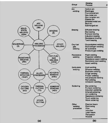
and radiant energy (Kalpakjian.S, 2001). Referring to the Master Chart of Welding of
AWS, welding process is classified as Arc Welding (AW), Brazing (B), Solid State
Welding (SSW), Soldering (S), Resistance Welding (RW) and Oxyfuel Gas Welding
(OFW) (Jefus.L, 2004).
Figure 2.1: Master Chart of Welding and Allied Process (AWS).
2.2.1 Arc Welding
The term arc is like lighting and actually a form of emitted gas (Killing.R, 2001). In
arc welding process, the source of heat is received from electrical energy. The arc is
generated between the tip of electrode and the work piece (Kalpakjian.S, 2001). The
types of welding categorized in this section are Shielded Metal Arc (SMAW), Gas
Metal Arc (GMAW), Flux Cored Arc Welding (FCAW) and Gas Tungsten Arc
Welding (GTAW)(Figure 2.1).
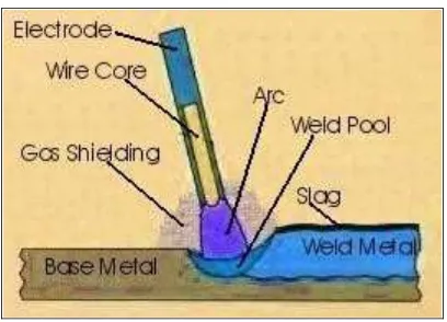
2.2.1.1 Shielded Metal Arc Welding (SMAW)
Shielded Metal Arc Welding is categorized as one of oldest, simplest and
versatile joining process. The basic principle of this welding process, weld forms
when molten metal from the tip of the consumable electrode flows together with the
molten metal from the edges of the work piece. The coating of electrode provides
shield to the weld area (Figure 2.2) (Kalpakjian.S, 2001). The advantage of this
process is low cost. The weld is high quality if the suitable electrode is selected.
However, the most important factor affecting the quality is the operator skill because
the process is normally done manually (Houldcrof.P, 1990). The process is best
suited for work piece thickness of 3mm-19mm (Kalpakjian.S, 2001). Field of
applications suggested for this welding process are in structural steel work,
shipbuilding, general engineering, process plant, pipe work repairs and maintenance
Figure 2.2: Shielded Metal Arc Welding Process.
Source: American Metallurgical Consultants (1999)
2.2.1.2 Gas Metal Arc Welding (GMAW)
This welding process uses a continuous solid electrode and a gas to shield the
arc and molten pool (Figure 2.3). The process is flexible because the wire feed unit
can be separated from the welding gun with a flexible conduit down which the wire
is fed. The welding is carried out on thin material. The position of welding in
GMAW is vertical and other positions. Since GMAW is a continuous process it is
suitable for operations attached on welding robots. GMAW welding process is
suitable for fillet welds. The welding material applicable is non-ferrous metal such as
aluminum and copper base. This process is highly used in shipbuilding, structural,
process plant, electrical, domestic equipment and automobile industries
(Houldcrof.P, 1990). Figure 2.4 shows Gas Metal Arc welding. GMAW is also
Figure 2.3 Gas Metal Arc Welding Process.
Source: American Metallurgical Consultants (1999)
Figure 2.4: GMAW Welding.
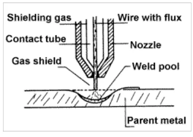
2.2.1.3 Flux Cored Arc Welding (FCAW)
FCAW is an arc welding using a continuous hollow electrode filled with a flux
which provides shielding gases, deoxieders, alloy additions and slag formers as
shown in Figure 2.5. Some cored electrodes are designed to use with an additional
gas shield, which is usually carbon dioxide or carbon dioxide rich gas mixture. An
argon based gas shield is always used with metal-cored wires. This welding is
normally non-automated. The advantage of flux wired is having high deposition rates
and give deep penetration. Preference to choose the type of solid wires depends on
economic considerations. The process is widely used in structural engineering, earth
moving plant, shipyard and offshore fabrications. It is frequently used for welding
stainless steels and widely employed for hard surfacing. The equipment can be
operated by robot (Houldcroft.P, 1990).
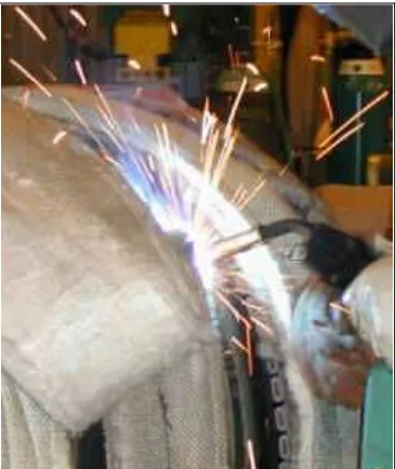
Figure 2.5 FCAW Welding Process.
Source: Johnson.C (2003).
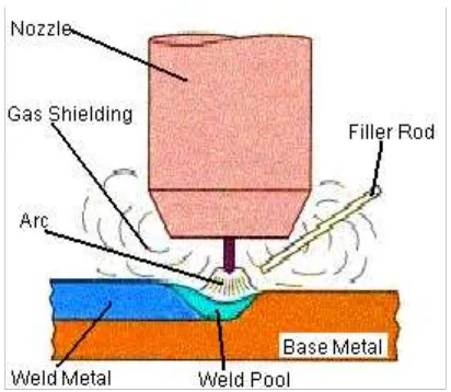
2.2.1.4 Gas Tungsten Arc Welding (GTAW)
GTAW welding process is an arc process in which arc is struck by a non
consumable electrode of tungsten to the work, the electrode, arc and molten pool
being shielded by a stream of inert gas commonly argon. Filler metal is added
separately when needed as shown in Figure 2.6. GTAW welding is a precision
do not require filler metal. GTAW welds are high quality, therefore certain metals
and alloys cannot be used. GTAW results in good penetration and deposition rate.
However both penetration and deposition rate is much less than MIG. GTAW is
commonly used in automobile, aerospace power generation, process plant and
electrical and domestic equipment manufacture (Houldcroft .P, 1990).
Figure 2.6: GTAW Welding Process.
Source: American Metallurgical Consultants (1999)
2.2.2 Brazing
Brazing is a joining process different from normal arc welding. In brazing a
metal or alloy having a melting point lower the parent metal is made to flow by
capillary attraction into the space between the parts to be joined under the action of
heat. The joint is design to allow capillary attraction by having a gap sufficient for
the flow of appropriate flux and brazing alloy (Houldcroft.P, 1990). Brazing can be
as described above or braze welding whereby the principle is similar to oxyfuel gas
welding using filler metal as shown in Figure 2.7 (Kalpakjian.S, 2001). Brazing is
one of the most versatile methods of joining metals in use today. Brazed joints are
braze materials perform well in abrasive, corrosive and high temperature conditions.
Brazing has become popular and effective in a variety of industrial uses as well as
gas turbine applications (Sermatech International, 2008). An example of application
is also in joining carbide to tool bit as shown in Figure 2.8.
Figure 2.7: Brazing a Butt Joint.