Published in IET Electric Power Applications Received on 30th November 2009 Revised on 11th August 2010 doi: 10.1049/iet-epa.2009.0287
Special Section – Electrical Machines and Drives for the More Electric Aircraft
ISSN 1751-8660
Rotor losses in fault-tolerant permanent
magnet synchronous machines
T. Raminosoa C. Gerada N. Othman L.D. Lillo
Department of Electrical and Electronic Engineering, The University of Nottingham, University Park, Nottingham NG7 2RD, UK E-mail: [email protected]
Abstract:The necessary reliability of safety-critical aerospace drive systems is often partly achieved by using fault-tolerant (FT) electrical machines. There are numerous published literatures on the design of FT machines as well as on control algorithms used to maintain drive operation with an incurred fault. This study is set to look at the rotor losses in three- and five-phase surface mount permanent magnet machines when operating in faulty mode in order to highlight the influence of the post-fault control strategy and winding configuration. Although the work presented in this study is mainly focused on FT control methodologies targeted at mitigating phase open circuit faults, the implications of short-circuit faults is also considered and discussed.
1
Introduction
In a fault-tolerant (FT) machine, when a phase (or a group of phases) is disabled as a consequence of an open-circuit or short-circuit fault the remaining phase currents are controlled in such a way as to maintain the same pre-fault positive sequence armature rotating field to interact with the fundamental rotor-produced field and thus maintain the same average torque as in healthy operation unless degraded operating conditions are allowed for. Degraded operation requirements often define rated, peak and ripple torque limits. Whatever the post-fault operating requirements are, one needs to understand the loss mechanisms in such operating conditions in order to be able to correctly choose the machine topology, winding configuration, machine size and control strategy. The stator copper loss is straightforward to calculate in such conditions; however, the additional losses in the rotor conducting components are not. The unbalanced nature of the armature magnetic field during faulty operation may change the magnitude of the existing eddy current harmonic components and possibly introduce others depending on the control strategy and winding configuration. Considerable work has been done to investigate the best control methodology to obtain a smooth torque in faulty operation [1, 2]. However, to the authors’ knowledge, little effort has been made towards investigating the effects of the FT control methodology on
the machine losses, particularly in the rotor conducting components [3]. This issue is quite important since the amount of power loss will limit the torque capability of the machine in FT operating mode. In [3], for example, an interesting FT control strategy aimed at minimising torque ripple by shaping the current waveforms in the remaining healthy phases was successfully implemented; however, it was reported that this led to significant increase in the magnet eddy current losses. During faulty operation, the increased armature current and the unbalanced nature of the phase currents and winding distribution give rise to amplified forward and backward rotating harmonic fields. These induce eddy currents in the sleeve, magnets and possibly the rotor magnetic core. As heat removal is particularly difficult from the rotor, the magnets can heat up and experience irreversible demagnetisation, thus diminishing the machine power capability. This paper is set to investigate the effects of FT operation on rotor losses of three- and five-phase surface mount permanent magnet (PM) machines when various control algorithms and winding configurations are used. Towards this aim, an eddy current loss calculation method able to account for rotor loss in the presence of an unbalanced field distribution will first be presented and then applied to analyse the post-fault machine operation of a number of FT machine designs.
losses in FT operation. Finite element (FE) models will be subsequently used to verify the proposed modelling approaches. The analysis is carried out in 2D and any 3D phenomena such as end effects and axial segmentation are not considered in this study. Previous research papers have shown that 2D analysis generally overestimates the calculated rotor eddy-current losses when compared with 3D calculations [4–6]. However, according to [5], for the axial length to pole pitch ratio of the machines considered, the end effects are expected not to be significant. The time harmonic method will give an insight into the losses produced by each of the rotating fields produced by the armature magneto-motive force (MMF) in faulty conditions. Within this paper, a range of three- and five-phase surface mount, FT, PM machines with similar power rating but various winding configurations will be looked at in terms of their operating losses. The machines considered are summarised inTable 1and detailed in Appendix 2. They are all of concentrated coil design with a sub-unity slot per pole per phase. Such designs are characterised by a harmonic-rich armature field which can cause a significant increase in losses in the rotor conductive components when the machine operates in faulty conditions.
In the next section, methods for determining the armature field components and their respective rotor induced losses in faulty operation will be described. Various post-fault control strategies will then be considered for each machine configuration and the rotor loss components determined. The implications of the winding configuration and control strategy adopted will then be discussed.
2
Evaluation of rotor loss
In this section two methods for determining the rotor losses will be described. The first method is based on an analytical magnetostatic time-stepping model, the second based on a time harmonic current sheet method.
2.1 Analytical time-stepping method
This method is based on an analytical magnetostatic time-stepping model[7, 8]. It being so, the reaction field of the induced eddy currents is not taken into account. This is,
however, a valid and realistic assumption considering that these currents are mostly resistance limited at relatively low excitation frequencies[9 –12]. The eddy currents created by the armature winding field are derived from the vector potential Az(t) in the magnet region. The detailed calculation of the vector potential is presented in Appendix 1. The eddy current density at any point in the magnet cross section is given by
Jeddy(t)= − 1
Thus, at any point of the magnet, the waveform of the eddy current density is obtained from the waveform of the vector potential by performing a numerical time derivation. In (1),
rm is the resistivity of the magnet and C(t) is a
time-dependent function which has to be chosen to impose a zero net current through the cross section of the considered magnet block [9, 11]. Actually, C(t) is the spatial average of (dAz/dt) over the magnet cross section [11, 13]. Each
magnet block is subdivided into several elements as shown in Fig. 1 and the waveform of the eddy current losses in this magnet is calculated by (2)
Peddy per magnet=
wherelaxial is the axial length of the machine and sectkthe
surface of thekth element.
An identical method is used to calculate the eddy current in the non-magnetic conducting sleeve forming only one component and also subdivided into several elements (Fig. 1). The rotor core for the machines considered is laminated and thus is neglected in this study.
Fig. 2areports the effect of the magnet subdivision on the eddy current loss waveform in one magnet for Machine 3a. It can be noticed that a circumferential subdivision of 25 and a radial subdivision of five are sufficient to achieve an accurate computation of the eddy current loss in one magnet block.
Figs. 2bandccompare the waveforms of the eddy current density in one corner of the magnet and in one point of the Table 1 Studied machines
outer diameter 134 134 134
axial length 100 100 100
sleeve obtained from the proposed time-stepping method and that obtained from an FE transient simulation for the three-phase, 24 slot 20 pole motor in healthy operation.
Fig. 3 compares the eddy current losses in one magnet from the analytical time-stepping and FE transient methods for a five-phase machine. Having validated this method, the next subsection will look at the current sheet time harmonic method.
2.2 Current sheet time harmonic method
This modelling method is based on first identifying the field space harmonics present in the airgap owing to the armature currents and then, for each harmonic, calculating the sinusoidal distributed current sheet located on the stator bore surface reproducing the same magnitude of the airgap radial flux density. Similar approaches have been used in[14 –16]. These approaches, however, do not account for the discrete magnets or, in other words, for eventual circumferential segmentation. They have also not considered faulty, unbalanced operation.
In order to consider an unbalanced winding set only one phase current is considered at a time. This was set equal to the rated peak value (Im). In this way, all the space harmonic content of one phase susceptible to persist in any unbalance FT operating mode are preserved. Some harmonics eventually cancel out under healthy operation as pointed out byFigs. 4aandcand each space harmonic will induce only one rotor current frequency in this operating mode.
Unlike healthy operation, each space harmonic fieldnwill induce one or two frequencies (clockwise or anticlockwise or both) in the rotor conducting components depending on the nature of the winding and the way it is supplied. These frequencies are given by the following relation
frotor(n)= |n+sgnp|fmech (3)
where sgn¼+1 or 21 for backward and forward rotating
field, respectively, andpis the number of pole-pairs.
A time harmonic simplified FE model of the machine is built for each frequency and the corresponding losses are calculated (Fig. 5). The analysis is performed according to the following steps:
Figure 2 Machine 3a: effect of magnet subdivision on the eddy current losses waveform in one magnet
a Eddy current densities from the time-stepping analytical and FE transient models
b External corner of a magnet in healthy operation
c One point of the sleeve in healthy operation
1. For a given armature space harmonicn
† the frequency induced by each rotating field is determined using (3);
† the magnitudes of the rotating fields for each direction are calculated according to (4) –(13).
2. For each rotating field
† an equivalent current sheet is applied to the time harmonic FE model to replicate the same airgap magnetic field harmonic determined from step 1;
† the model frequency is set according to the considered rotating field.
In the model, each magnet block was defined as a solid conductor circuit driven by a zero-current source (insulated magnet blocks). The eddy current losses created by each rotating field in one magnet are then calculated and the eddy current losses attributed to a particular space harmonic is simply the addition of the losses created by its forward and backward rotating fields. The above process is automated using the scripting feature of the FE software package MagNet. Fig. 5 shows the layout of the time harmonic current sheet model due to 14th space harmonic in healthy mode. Owing to the balanced supply in healthy mode, only one travelling wave, and thus one rotor frequency exists for any space harmonic.
The current sheet time harmonic method is then validated by comparing it with the previously validated analytical method and with a full time-stepping transient FE simulation for three- and five-phase machines in both healthy and FT modes.Figs. 6–8show the losses owing to Figure 4 Armature reaction airgap flux density spectra
a Machine 3a
b Machine 3b
c Machine 5
Figure 5 Layout of the current sheet model and distribution of the eddy current density owing to the 14th space harmonic for a 24 slots 20 poles machine
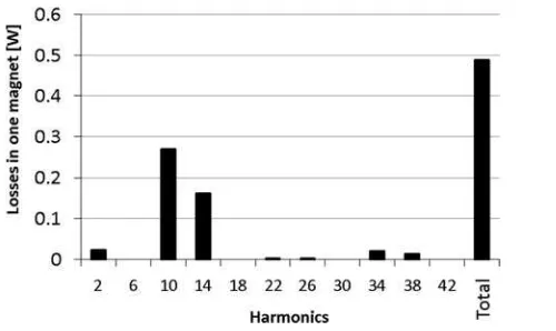
each harmonic in one magnet and in the sleeve of Machine 3a (three-phase machine) operating in healthy and FT modes, respectively, as will be explained later on. Similarly,
Figs. 9–11 show similar comparisons for the five-phase machine (Machine 5) in healthy and FT modes, respectively. Figs. 6a and 8 compare the total losses
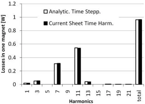
obtained from both models to those obtained from a transient FE simulation incorporating material non-linearities and stator slotting effects. Very good agreement is observed for any machine in any mode of operation. Figure 7 Machine 3a: losses due to each space harmonics
in one magnet under healthy operation a Losses in one magnet
b Losses in sleeve
Figure 8 Machine 3a: losses owing to each space harmonics in one magnet when one phase is lost and the magnitude of remaining currents scaled by 1.5 (Method 3-1)
Figure 9 Machine 3a: losses owing to each space harmonics in one magnet when one phase is lost and FT strategy without neutral connection is used (Method 3-2)
Figure 10 Machine 3a: losses owing to each space harmonics in one magnet
a When one phase is lost and FT strategy with current shifting is used (Method 3-3)
3
Resulting armature field of
faulty three-phase machines
Three FT strategies for three-phase machines are analysed. In all cases, the currents are set so that the rated positive sequence torque is maintained. The corresponding current vector diagrams are depicted inFig. 12.
3.1 Method 3-1
The most straightforward way to operate a three-phase machine after an open-circuit fault is just to increase the current magnitude of the remaining healthy phases to compensate for the lost torque contribution of the faulty phase while the phase angles of the remaining currents are kept identical to the healthy case. The necessary current
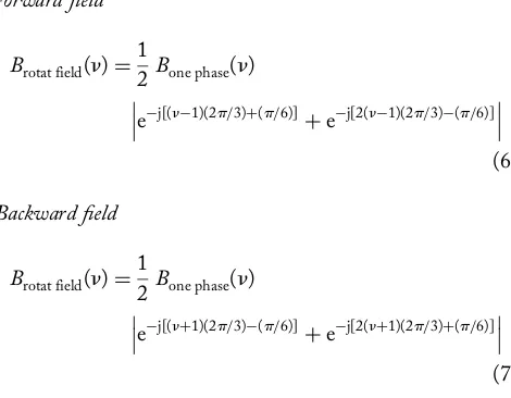
magnitude overrating is 1.5. This FT control strategy is achievable if each phase is fed by a separate converter [17]. The relations used to calculate the magnitude of the resulting rotating fields because of each armature harmonic for the current sheet time harmonic method are
Forward field
Brotat field(n)=1
2Bone phase(n) e
−j[(n−1)(2p/3)]+e−j[2(n−1)(2p/3)] (4)
Backward field
Brotat field(n)=1
2Bone phase(n) e
−j[(n+1)(2p/3)]+e−j[2 (n+1)(2p/3)] (5)
For this control strategy, all space harmonics exist and each of them creates rotating fields in both directions (Table 2).
3.2 Method 3-2
If the three phases are fed by a single inverter and the neutral point of the machine is not accessible, operation can be maintained (with large torque pulsations) by controlling the current of the two remaining healthy phases which are now connected in series (Fig. 12). Assuming phaseAis lost, the resulting phase of BandCcurrents are shifted 308towards Figure 11 Machine 3b: losses owing to each space
harmonics under healthy operation
a Losses in one magnet
b Losses in sleeve
Figure 12 Machine 3b: losses owing to each space harmonics in one magnet when one phase is lost and the magnitude of remaining currents scaled by 1.5 (Method 3-1)
Table 2 Harmonic rotating fields of Machine 3a under Method 3-1
n 2 6 10 14 18 22 26 30 34 38 42
healthy 2 0 + 2 0 + 2 0 + 2 0
the phasor of the pre-faultAcurrent, that is,iC¼2iB. Only
one current is effectively controlled. The current overrating in this case is 1.732. The relations used to calculate the magnitude of the rotating fields owing each harmonic for the current sheet time harmonic method are
Forward field
One can observe, from (6) and (7) that the resultant triplen harmonics owing to the two remaining phases are reduced to zero and do not create any rotating fields. Any non-triplen harmonic creates rotating fields in both directions (Table 3).
3.3 Method 3-3
To obtain a smooth output torque, the FT control strategy presented in [18] can also be used. This control needs a separate converter for each phase or a neutral point connection to the mid-point of the DC link capacitor. Assuming phaseAis lost, then, phaseBandCcurrents are shifted 308away from the phasor of the pre-fault phase A current (Fig. 12). The magnitude overrating is again 1.732. This control strategy cancels the negative sequence field produced by the torque-converting harmonic. The relations used to calculate the magnitude of the rotating fields owing
to each harmonic for the current sheet time harmonic method are
It can be observed from (8) and (9) that for any non-triplen space harmonic, either a forward or a backward field exists. However, triplen harmonics create rotating fields in both directions.Table 4summarises those observations.
4
Resulting armature field of
faulty five-phase machines
The FT control strategies analysed in this section are limited to two. Similar to the previous section the post-fault currents are regulated to produce the rated DC output torque. Two FT strategies are considered and the corresponding current diagrams are depicted inFig. 13.
4.1 Method 5-1
Just like for the three-phase machines, the most straightforward FT method is to just overrate the magnitude of the remaining healthy phases’ currents with their phase angles unchanged. This method is possible if each phase is fed by a separate converter. This will involve
Table 3 Harmonic rotating fields of Machine 3a under Method 3-2
n 2 6 10 14 18 22 26 30 34 38 42
healthy 2 0 + 2 0 + 2 0 + 2 0
Method 3-2 +/2 0 +/2 +/2 0 +/2 +/2 0 +/2 +/2 0
+, forward;2, backward; 0, cancelled
Table 4 Harmonic rotating fields of Machine 3a under Method 3-3
n 2 6 10 14 18 22 26 30 34 38 42
healthy 2 0 + 2 0 + 2 0 + 2 0
Method 3-3 2 +/2 + 2 +/2 + 2 +/2 + 2 +/2
a current overrating of 1.25. The phases of the remaining currents are kept identical to the healthy case. For the current sheet time harmonic method, the relation used to calculate the magnitudes of the harmonic rotating fields are given below for this FT control strategy:
Forward field
For this control strategy, all space harmonics exist and each of them creates rotating fields in both directions (Table 5).
4.2 Method 5-2
The second method considered is that for no zero-sequence current as in the case when using a single inverter for the machine without a neutral point connection [1, 2]. Assuming phase A is lost, the phases ofC and Dcurrents are kept identical to the healthy case and Band Ecurrents are set to iB¼2iD and iE¼2iC. The magnitude
overrating in this case is 1.382 to keep the same pre-fault fundamental positive sequence field. For the current sheet time harmonic method, the relation used to calculate the magnitudes of the harmonic rotating fields are given below for this FT control strategy
Forward field
From (12) and (13), it can be observed that this control strategy cancels the backward field owing to the torque-converting harmonic as well as the fields owing to any Figure 13 Machine 3b: losses owing to each space
harmonics in one magnet when one phase is lost and FT strategy without neutral connection is used (Method 3-2)
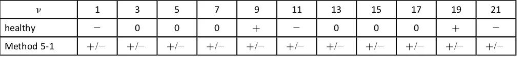
Table 5 Harmonic rotating fields of Machine 5 under Method 5-1
n 1 3 5 7 9 11 13 15 17 19 21
healthy 2 0 0 0 + 2 0 0 0 + 2
Method 5-1 +/2 +/2 +/2 +/2 +/2 +/2 +/2 +/2 +/2 +/2 +/2 +, forward;2, backward; 0, cancelled
Table 6 Harmonic rotating fields of Machine 5 under Method 5-2
n 1 3 5 7 9 11 13 15 17 19 21
healthy 2 0 0 0 + 2 0 0 0 + 2
Method 5-2 2 +/2 0 +/2 + 2 +/2 0 +/2 + 2
harmonic multiple of 5. Table 6 summarises the existing rotating fields and their directions under this control strategy.
5
Losses during fault-tolerant
operation of three-phase machines
The models described in the previous sections were applied to the machines considered in this work to evaluate the rotor losses during healthy and faulty operation. The stator copper loss will increase according to the increase of the phase current magnitude for the various post-fault control strategies. The eddy current losses in the magnets and sleeve during faulty operation were expected to be higher than in healthy operation. This, however, was not always the case. It depends on the winding configuration and the control method as will be discussed in this section. The loss computation was done up to the 42th harmonic for the Machine 3a and till the 64th for the Machine 3b since the losses owing to higher-order space harmonics were found to be very low.The rotor losses are the highest for the FT control without neutral connection (Method 3-2) despite the cancellation of triplen harmonic fields (Figs. 7,8a,14–17). Moreover, the torque ripple is extremely high (Figs. 18 and 19). The reason is the high magnitude of the negative-sequence field of the torque-converting space harmonic (high losses owing to harmonic 10 for Machine 3a in Fig. 14and harmonic 8 for Machine 3b inFig. 16). The main advantage of such a system would be the reduced component count from point of view of the converter.
As to the two other methods (Methods 3-1 against 3-3); Method 3-3 creates higher losses in Machine 3a and lower losses in Machine 3b (Figs. 8aand17). The reason for this is the presence of triplen harmonics in the field created by one phase of Machine 3a which do not cancel out during unbalanced operation (Fig. 4a). We can see this by comparing the losses owing to each harmonic of Machine
3a during healthy and faulty operation when adopting the FT control Method 3-3. (Figs. 6a and 8a, respectively). The losses owing to each of the space harmonics are the same except for the triplen harmonics which appear in the Figure 15 Current diagrams for healthy and various FT strategies for five phase machine
Figure 14 Machine 3b: losses owing to each space harmonics in one magnet when one phase is lost and FT strategy with current shifting is used (Method 3-3)
Figure 16 Machine 5: losses owing to each space harmonics in under healthy operation
a Losses in one magnet
faulty mode creating additional losses. For Machine 3b, there are not any triplen harmonics in the single-phase MMF under both healthy and faulty operation owing to the coils being pitched by 2/3 (Fig. 4b). Thus, the losses in healthy
mode and in this FT control strategy are exactly identical (Figs. 17a and 20). The torque waveform is also identical to the healthy case as shown inFig. 19.
6
Losses during fault-tolerant
operation of five-phase machines
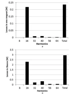
As expected, the eddy current losses in magnets and sleeve are higher in any FT mode compared to healthy operation owing to the amplified harmonic rotating fields. For the five-phase (Machine 5), the loss computation was done till the 21st harmonic since the losses owing to higher-order space harmonics were found to be very low.Eddy current losses are the highest for the non-connected neutral FT control strategy (Method 5-2) – (Fig. 11 and
Table 7). The control strategy consisting in simply scaling the remaining currents by 1.25 of the healthy current magnitude is very attractive (Method 5-1). The torque ripple is not significantly larger compared to the previous one and both copper losses and rotor losses in FT operation are lower (Figs. 10and21).
7
Discussion on the selection of
a fault-tolerant control strategy
While the rotor losses on their own do not constitute the basis for the selection of a control strategy and a winding configuration, their consideration is important especially if the motor is cooled through the stator outer surface as they have the highest thermal resistance path to the cooling medium. The balance of stator and rotor losses for a particular machine design will also be a determining factor in the selection process.Figure 17 Machine 5: losses owing to each space harmonics in one magnet when one phase is lost and the magnitude of remaining currents scaled by 1.25 (Method 5-1)
Figure 18 Machine 5: losses owing to each space harmonics in one magnet when one phase is lost and without neutral connection is used (Method 5-2)
Considering the three-phase machines; although the current phase shifting (Method 3-3) produces lower torque ripple (Fig. 18), for machines having triplen harmonics in their armature single-phase field (Machine 3a), just increasing the phase current magnitude by 1.5 (Method 3-1) to keep the same average torque as in healthy mode appears to be interesting from the point of view of losses. Such a control method needs a lower current overrating compared to the two other methods and thus lower copper
losses and in addition lower eddy current losses in the rotor conducting components (magnets and sleeve) (Figs. 7, 8a, 14 andTable 8).
For machines not having triplen harmonics present in the armature field of a single phase (Machine 3b), the losses in the rotor conducting components as well as the torque waveform are exactly identical to the healthy case when Method 3-3 is used. This is of high importance since there Figure 20 Torque of Machine 3b under healthy and various FT modes
Table 7 Loss distribution of a five-phase machine [W]
Machine Healthy Method 5-1 Method 5-2
Stator Rotor Stator Rotor Stator Rotor
5 441 17.5 551 22.5 673 28.7
is no increase in the torque ripple and no increase in the losses in any rotor conducting components (Figs. 17,19and20a).
For the five-phase machine; eddy current losses are the highest for Method 5-2. Moreover, the current overrating (1.382) is the highest and consequently the increase in the copper losses is the highest as well (Table 7). Thus, for the Machine 5, the only advantage of this control strategy is the slightly lower torque ripple.
It is worth noting that the slot pole combination opted for in an FT machine will determine the nature of the rotor losses. Opting for a winding pitch which eliminates the third harmonic field (three slots per pole pair) for a three-phase machine can be beneficial in terms of post-FT operating performance (lower torque ripple and lower rotor loss) in spite of the reduced fundamental winding factor. This work has also given an insight into an effective method for determining the rotor losses at the motor design stage. Accounting for the rotor losses during faulty operation and considering the control strategy to be adopted may shift the optimum machine geometrical parameters and winding configuration.
The work presented in this paper has focused on control methodologies applied to FT drives mainly targeted at mitigating phase open circuit faults. Depending on the application at hand, operation with short-circuit faults might also be a requirement. In such a case, it is then important to consider the resulting torque ripple and additional losses. A post-fault control method such as that adopted in[3] would be more adequate especially if large torque ripple is to be avoided. The main difficulty in analysing short-circuit faults for the control methods adopted in this paper stems from the fact that the resulting short-circuit fault current is unknown. Its magnitude and phase angle will mainly depend on the phase resistance, inductance and operating speed. Fig. 8b
illustrates the loss components in one magnet when control Method 3-3 is introduced after a short-circuit fault. For simplicity it was assumed that the resulting short-circuit current is limited to 1 p.u. and lags the back EMF of the shorted phase by 908. The short-circuit current in the faulted phase gives rise to extra losses for all space harmonics, especially for the torque-converting one (e.g. ten for the 24 slots 20 poles machine) which produces a non-synchronous backward rotating field. However, for the machine considered, the extra losses produced appear to be small compared to the losses produced by the triplen harmonics (mainly six). Thus, the main issue to deal with when using this control strategy would be the significant torque ripple owing to the
fundamental negative sequence created by the shorted phase. Adopting a 1208coil pitch will still be beneficial in the case of terminal short-circuit faults as this will always show lower losses in FT mode with Method 3-3 since the losses produced by triplen harmonics are the most significant. Rotor losses arising from short-circuit winding faults need further investigation and will be an area of future work.
8
Conclusion
This work presents some of the issues to consider when rating FT PM machines to work with various remedial control methods. The increase of copper and rotor eddy current losses were compared for various FT control strategies for three- and five-phase machines. Tables 7 and
8summarise the results discussed.
Three-phase machines that have no triplen harmonics in their single-phase airgap field can be controlled using Method 3-3 to operate in faulty conditions with the same torque ripple and rotor loss as during healthy operation. If torque ripple and an increase on rotor losses is acceptable, then using Method 3-1 can give the minimum overall loss. On the other hand, machines which have triplen harmonics in their single-phase MMF always show higher torque ripple in FT mode of operation. For those machines, however, Method 3-3 offers the lowest torque ripple among the considered FT strategies. For the machines considered, Method 3-1 always gives the best efficiency.
For a five-phase machine, if the phases are fed by separate converters, the simple current scaling strategy (Method 5-1) appears also to be the most appealing in terms of copper losses and rotor losses. The resulting torque ripple is just slightly higher than the FT strategy without neutral connection (Method 5-2).
The approaches developed to determine the rotor eddy current losses which have been validated through FE results, should be used at the design stage of the machine alongside an appropriate thermal model to ensure the magnet temperatures do not exceed the allowable values.
9
References
[1] BIANCHI N.,BOLOGNANI S.: ‘Fault-tolerant PM motors in automotive applications’. IEEE Conf. on Vehicle Power and Propulsion, 7 – 9 September 2005, pp. 747 – 755
Table 8 Loss distribution of three-phase machines [W]
Machine Healthy Method 3-1 Method 3-2 Method 3-3
Stator Rotor Stator Rotor Stator Rotor Stator Rotor
3a 441 9.3 661 14.7 882 21.5 882 18.7
[2] BIANCHI N., BOLOGNANI S., PRE M.D.: ‘Impact of stator winding of a five-phase permanent-magnet motor on postfault operations’,IEEE Trans. Ind. Electron., 2008, 55, (5), pp. 1978 – 1987
[3] EDE J.D.,ATALLAH K.,WANG J., HOWE D.: ‘Effect of optimal torque control on rotor loss of fault-tolerant permanent-magnet brushless machines’,IEEE Trans. Magn., 2002,38, (5), pp. 3291 – 3293
[4] EDE J.D.,ATALLAH K.,JEWELL G.,WANG J.,HOWE D.: ‘Effect of axial segmentation of permanent magnets on rotor loss in modular permanent magnet brushless machines’, IEEE Trans. Ind. Appl., 2007, 43, (5), pp. 1207 – 1213
[5] CHEBAK A.,VIAROUGE P.,CROS J.: ‘Analytical computation of the full load magnetic losses in the soft magnetic composite stator of high-speed slotless permanent magnet machines’,IEEE Trans. Magn., 2009,45, (3), pp. 952 – 955 [6] WANG J., PAPINI F., CHIN R., ARSHAD W.M., LENDENMANN H.: ‘Computationally efficient approaches for evaluation of rotor eddy current loss in permanent magnet brushless machines’. Int. Conf. on Electrical Machines and Systems, ICEMS, 2009, pp. 1 – 6
[7] ZHU Z.Q.,HOWE D.,CHAN C.C.: ‘Improved analytical model for predicting the magnetic field distribution in brushless permanent-magnet machines’, IEEE Trans. Magn., 2002, 38, (1), pp. 229 – 238
[8] ZHU Z.Q., HOWE D.: ‘Instantaneous magnetic field distribution in brushless permanent dc motors. Part ii: armature-reaction field’,IEEE Trans. Magn., 1993,29, (1), pp. 136 – 142
[9] ISHAK D.,ZHU Z.Q.,HOWE D.: ‘Eddy-current loss in the rotor magnets of permanent-magnet brushless machines having a fractional number of slots per pole’,IEEE Trans. Magn., 2005,41, (9), pp. 2462 – 2469
[10] TODA H.,XIA Z.,WANG J.,ATALLAH K.,HOWE D.: ‘Rotor eddy-current loss in permanent magnet brushless machines’,
IEEE Trans. Magn., 2004, 40, (4), Part 2, pp. 2104 – 2106 [11] AMARA Y.,WANG J.,HOWE D.: ‘Analytical prediction of eddy-current loss in modular tubular permanent-magnet machines’, IEEE Trans. Energy Convers., 2005, 20, (4), pp. 761 – 770
[12] ATALLAH K.,HOWE D.,MELLOR P.H.,STONE D.A.: ‘Rotor loss in permanent-magnet brushless AC machines’, IEEE Trans. Ind. Appl., 2000,36, (6), pp. 1612 – 1618
[13] DEAK C.,PETROVIC L.,BINDER A.,MIRZAEI M.,IRIMIE D.,FUNIERU B.: ‘Calculation of eddy current losses in permanent magnets of synchronous machines’. SPEEDAM 2008, 11 – 13 June 2008, pp. 26 – 31
[14] IRENJI N.T.: ‘Calculation of rotor electromagnetic losses in high-speed permanent magnet machines’, PhD dissertation, University of Southampton, Southampton, UK, 1998
[15] CHO H.W., JANG S.-M.,CHOI S.-K.: ‘A design approach to reduce rotor losses in high-speed permanent magnet machine for turbo-compressor’, IEEE Trans. Magn., 2006, 42, (10), pp. 3521 – 3523
[16] MECROW B.C.,JACK A.G.,ATKINSON D.J.,ET AL.: ‘Design and testing of a four-phase fault-tolerant permanent-magnet machine for an engine fuel pump’, IEEE Trans. Energy Convers., 2004,19, (4), pp. 671 – 678
[17] LEVI E.: ‘Multiphase electric machines for variable-speed applications’, IEEE Trans. Ind. Electron., 2008, 55, (5), pp. 1893 – 1909
[18] GERADA C.,BRADLEY K.: ‘Integrated PM machine design for an aircraft EMA’, IEEE Trans. Ind. Electron., 2008, 55, (9), pp. 3300 – 3306
10
Appendix 1
10.1 Calculation of the vector potential
owing to one armature coil
The notations in below are adopted
In the one coil field, all space harmonics are present [4]
v=1, 2, 3, 4, . . .,1
The relative permeability of the magnets is assumed to be 1, and thus, for the armature reaction field, they behave like air. Only one ‘air zone’ is then considered and its effective thickness is
d=q+hm′
The following expressions have been proposed in [4] and [5]
g radius coordinate
u angular coordinate
Rs stator bore radius
Rm magnet outer radius
Rr magnet inner radius
hm¼Rm2Rr magnet height
q¼Rs2Rm airgap
Nturns number of turns of a wound tooth
ay coil span
The pitch factor is defined as
Kpv =sin vay 2
The slot opening factor is defined as
Ksov = sin(vb0/2Rs)
(vb0/2Rs)
The curvature factor is defined as
Frv(r)=dv
r r Rs
v
1+(Rr/r)zv 1−(Rr/Rs)zv
Then thevth harmonic of the radial airgap flux density is given by
Brv(r)= 2m0 p
islot
d
1
vKsovKpvFrv(r)
whereislotis the total current flowing through one side of a wound
tooth.
The vector potential at any point of the ‘air zone’
Azby coil(r,u)=
x
v=1,2,3,4,...
r
vBrv(r) sin(v(u−utooth))
where utooth is the angular coordinate of the centre of the
wound tooth.
The vector potentials owing to all current carrying coils in the armature are then superimposed to obtain the resultant vector potentialAzfor any rotor position.
By making a series of magnetostatic calculation for different positions of the rotor with the corresponding imposed phase currents, the waveform Az(t) of the magnetic vector potential at any point of the ‘air zone’ can be obtained.
11
Appendix 2
11.1 Additional technical data on the
machines considered
The machines considered operate at 1140 rpm. Magnet material used is NdFeB with Hc¼819 975 A/m. Sleeves are 0.5 mm thick and made of Inconel 718. The schematics of the machines geometry and winding configurations are given inFigs. 22–24.
Figure 23 Machine 3b


![Table 8 Loss distribution of three-phase machines [W]](https://thumb-ap.123doks.com/thumbv2/123dok/592549.70760/12.595.43.553.89.162/table-loss-distribution-of-three-phase-machines-w.webp)
