i
CENTRALIZED WIRELESS SENSOR NETWORK DEPLOYMENT
MAGESWARAN A/L R JAGANATHAN
This report is submitted in partial fulfillment of the requirements for award of Bachelor of Electronic Engineering (Telecommunication Electronics) With
Honours
Faculty of Electronic and Computer Engineering Universiti Teknikal Malaysia Melaka
iii
“I hereby declare that this report is the result of my own work except for quotes as cited in the references.”
iv
“I hereby declare that I have read this report and in my opinion this report is sufficient in terms of the scope and quality for the award of bachelor of Engineering
(Industrial Electronics) With Honors.”
Signature : ……….
Supervisor’s Name : Mr. Mohd Riduan b. Ahmad
v
vi
ACKNOWLEDGEMENT
First and foremost, a special expression of gratitude is extended to my PSM supervisor, Mr. Mohd Riduan b. Ahmad for his non-stop guidance and support that really improved me theoretically and technically to carry out this project. I would to thank him again for being so understanding and allocate his time from his busy schedule to solve the problem I faced throughout this project.
Secondly, I would like to thank my family member and my brother especially for their support and encouragement given to me to carry out this project successfully.
vii
ABSTRAK
viii
ABSTRACT
ix
TABLE OF CONTENTS
CHAPTER TITLE PAGE
PROJECT TITLE i
BORANG PENGESAHAN STATUS LAPORAN ii
x
2.2 Hardware Familiarization 17
2.2.1 Hardware Architecture 18
2.2.2 Battery Opration 20
2.3 Software Overview 21
2.3.1 MoteView 2.0F 21
2.4 Software Manipulation 30
2.4.1 MoteWorks 2.0 30
2.4.2 MoteConfig 31
2.4.3 TinyOS 32
2.4.4 Programmer‟s Notepad 33
xi
3.2 Hardware Setup 44
3.2.1 Connecting Sensor Node to local PC 44 3.3 Deployment of Wireless Sensor Network 45 3.3.1 Selection of Network Topology 46
3.3.2 Site Specification 46
3.3.3 Estimation of Network Performance 48
3.4 Project Schedule 49
3.5 Summary 50
IV RESULT AND ANALYSIS
4.0 Introduction 51
4.1 Results 52
4.1.1 Estimation of Battery Lifetime 52
4.1.2 RF Power Analysis 54
4.2 Test-Bed Implementation 57
4.2.1 Indoor 57
4.2.2 Outdoor 58
V CONCLUSION AND RECOMMENDATION
5.0 Introduction 60
5.1 Conclusion 60
5.2 Future Works 62
xii
LIST OF TABLES
NO TITLE PAGE
2.0 Resources of the ATmega128 family Microprocessors 13
2.1 Hardware Platform Summary 19
2.2 Typical Operational Currents for IRIS peripherals 20
xiii
2.0 Overview of main sensor node hardware components 10
2.1 IRIS Mote 11
2.2 ATmega1281 Microprocessor Pinout 12
2.3 Base Station . 16
2.4 IRIS Professional Kit . 18
2.5 IRIS Hardware Architecture 19
2.6 Screenshot of Moteview GUI 22
2.7 Screenshot of a demo database displayed in Data tab 23
2.8 System Configuration in the Command Tab 24
2.9 Screenshot of the demo database in the Chart tab 25 2.10 Screenshot of the demo database in Health view 26
2.11 Demo database in Histogram view 27
2.12 Demo database in Scatter plot view 27
2.13 Demo database in Topology view 28
2.14 MoteConfig Application GUI 30
2.15 Interface of the Programmer‟s Notepad 33
2.16 MIB520 Programming Board 34
2.17 Antenna placement in LOS 38
2.18 Blockage caused NLOS 39
3.0 Connection to WSN via MoteView 2.0F 44
xiv
3.2 Points where sensor placed in indoor (LOS) 47
3.3 Points where sensor placed in indoor (LOS) 48
4.0 Comparison between different nodes using power calculator spreadsheet. 53 4.1 Energy Consumption for various RF power for Channel 11 54 4.2 Energy Consumption for various RF power for Channel 14 55 4.3 Energy Consumption for various RF power for Channel 26 55 4.4 The variation of energy consumption with RF Power and Sampling rate
modification 57
4.5 Effect of RF Power at outdoor testing 59
xvi
LIST OF APPENDIX
NO TITLE PAGE
A IRIS Datasheet 65
1
CHAPTER I
INTRODUCTION
1.0 Project Background
The focus of this project is on deployment of Wireless Sensor Network (WSN) using centralized (star) topology to analyze the propagation scenario of the sensor nodes and to optimize the energy level of the sensor nodes.
1.1.1 Wireless Sensor Network
2 Low power consumption - To support long-term operation, the power consumption of the radio link must be minimized so that devices can be powered by compact, lightweight batteries such as a coin cell battery for long periods of time.
Ease of Use - The network protocol allows the sensor network to initialize itself in a highly ad hoc, self-organizing manner.
Scalability - The network must support the number of nodes required immediately and must also be able to support future growth without causing exponential growth of overhead.
Responsiveness - Topology discover and re-discovery must be efficient, especially for applications where sensor nodes are mobile, such as in mobile machines or equipment or for wearable sensors. Range - The sensor nodes able to transmit data up to range of 500 meters. The range is depends on the type of sensor nodes used.
1.1.2 Topology
Network topology plays an important role in setting up the WSN for deployment. As we know there are many type of network topology such as star, mesh, tree, ring, bus and etc [2]. For this project purpose star or centralized topology is chosen and from there the advantages of the topology will analyze by creating a test-bed.
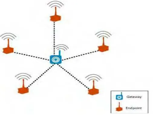
1.1.2.1Star Topology
A star topology is a single-hop system in which all wireless sensor nodes are within direct communication range usually 30 to 100 meters to the a gateway. All sensor nodes are identical and the gateway serves to
3
Figure 1.0 Star Topology
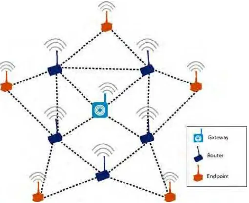
1.1.2.2Star Hybrid
4
Figure 1.1 Star Hybrid Topology
1.2 Problem Statement and Objective
1.2.1 Problem Statement
Most of existing device to measure the temperature and humidity are wired type, which means wires or cables need (e.g USB cable) to be attached to the control center (computer) to obtain required sensed data. There are some problems in using wired device where it involves lots of wire to be connected with the control center if data needed for different location. Another problem is when temperature and humidity need to be measured in long range of distance. It will be tedious to connect the device to the control center. So, by using wireless sensor network we can measure the temperature and humidity for different node and retrieve the data from a long distance.
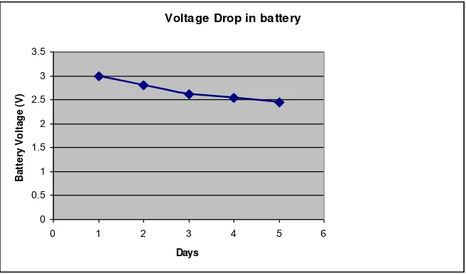
5 though at times the sensor node does not sense any parameter but it will transmit signal to the base station to stay connected with the topology. This makes the lifespan of the sensor node lower, thus the voltage of the sensor node must be monitored so that there are enough voltages for the sensor node to sense and send the data to the control center. For this project IRIS motes which are a Crossbow‟s product is used as the sensor nodes and base station. The user guide says the battery can last long till a year. A test is conducted to find out the voltage drop each day and the result obtained is plotted. From figure 1.2, the observation is each day the battery voltage drop is drastic and critical. In 5 days the battery voltage dropped from 3.0 V to 2.5 V. This proves that with the original settings of the IRIS sensor node, the battery cannot last long till a year.
The significant of this project is to deploy WSN in centralized topology with an optimum energy consumption. Since the main issue in WSN sensor nodes is the energy consumption, it will be ideal if a minimum energy is used by the sensor nodes to transfer the packets and data to the base station.
Voltage Drop in battery
6 1.2.2 Objectives
To deploy wireless sensor nodes in centralized topology for different propagation scenarios (test-bed implementation)
Indoor (LOS)
Outdoor (LOS)
To monitor the node time-by-time to make sure it remain in centralized topology.
To ensure RF Power (PTX) and Sampling Rate modification optimize
the energy consumption of the sensor nodes.
To come out with a best solution of parameter modification that produces the lowest energy consumption thus increases the lifespan of the sensor node.
1.3 Scope of Work
The scope of work involved in this project can be divided into four which are deployment, monitoring and data collection, analysis, and optimization.
1.3.1 Deployment
7 1.3.2 Monitoring and Collection
Monitoring involves monitoring the sensor node to observe whether the data of sensed parameters has been send correctly to the control center. Then the data form the control center need to be collected in a specific location such as database, MS Excel and etc. The collection is very useful for further analysis.
1.3.3 Optimization
Optimization process involves two matters which are manipulating the RF Power and changing the sampling rate. Both of this optimization process is done by using appropriate software.
1.3.4 Evaluation
Evaluation is mainly on the sensor nodes energy consumption of the sensor nodes. This analysis is done by tabulating and plotting graphs using the collected data to do a comparison between the normal sensor nodes and optimize sensor nodes.
1.4 Contribution of Project
8 1.5 Thesis Organization