ISSN: 1985-3157 Vol. 5 No. 2 July-December 2011 61 COMPUTER VISION BASED ROBOTIC POLISHING USING
ARTIFICIAL NEURAL NETWORKS
Dan, M.M.P.1 , Bani Hashim A.Y.1, Adnan, R.A.B.1, Ruzaidi, Z.1, Khairul, A.A.R.1, Rizal, M.S. 1, and Anton, S.P.2
1Faculty of Manufacturing Engineering, Universiti Teknikal Malaysia Melaka,
Hang Tuah Jaya, 76100 Durian Tunggal, Melaka, Malaysia
2Faculty of Information Science and Technology, Universiti Kebangsaan Malaysia, 43600 UKM Bangi, Selangor D.E., Malaysia
Author’s Email: [email protected]
ABSTRACT: Polishing is a highly skilled manufacturing process with a lot of constraints and interaction with environment. In general, the purpose of polishing is to get the uniform surface roughness distributed evenly throughout part’s surface. In order to reduce the polishing time and cope with the shortage of skilled workers, robotic polishing technology has been investigated. This paper studies about vision system to measure surface defects that have been characterized to some level of surface roughness. The
surface defects data have learned using artiicial neural networks to give a
decision in order to move the actuator of arm robot. Force and rotation
time have chosen as output parameters of artiicial neural networks. Results
shows that although there is a considerable change in both parameter values acquired from vision data compared to real data, it is still possible to obtain surface defects characterization using vision sensor to a certain limit of accuracy. The overall results of this research would encourage further developments in this area to achieve robust computer vision based surface measurement systems for industrial robotic, especially in polishing process.
KEYWORDS: polishing robot, vision sensor, surface defects, and artiicial neural networks.
1.0 INTRODUCTION
ISSN: 1985-3157 Vol. 6 No. 1 January-June 2012 Journal of Advanced Manufacturing Technology
62
and determine the action on the robot. For that, they need intelligent systems that can create a standard for classification of surface condition. One method that has proved much better for classification are artificial neural networks. Therefore, this research try to get time efficiency together with surface quality by combining contact and non-contact methods by using artificial neural networks as learning algorithm. The goal of this research work is to build the system act like human beings and has the ability in learning. The capabilities such polishing skilled worker is developed by using an intelligent robot with vision system using artificial neural networks to do polishing process in two dimensions specimen.
get the uniform surface roughness distributed evenly throughout part’s surface (Liao, L., Xi, F., and K. Liu, K., 2008). Traditionally, polishing has largely been a manual operation that is very labor intensive, highly skill dependent, inefficient with long process time, high cost, error prone, and hazardous due to abrasive dust. Automation is a solution to over come the above-mentioned problems of the manual operation. The importance of polishing automation has drawn many researchers into investigating robotic polishing technology. The major goal is to improve time efficiency together with surface quality.
Novel methods need to be developed in order to automate polishing process by industrial robots. In general, there are two methods that are developed by many researchers in the robotic polishing applications: contact methods & non-contact methods (Zhang, et.al., 2006). Contact method is usually chosen because it focuses on the quality of the result obtained. While non-contact methods only used for surface inspection and rarely used in the polishing process application. Though, some research had chosen non-contact method to reduce its processing time (Li, et.al., 2009).. For surface conditions, it may present an alternative way to allow the surface roughness to be measured rapidly with an acceptable accuracy. One of the most promising non-contact methods in terms of speed and accuracy is the computer vision technique. The surface roughness measured by computer vision system over a wide range could be obtained with a reasonable accuracy compared with those measured by traditional contact methods.
Recently, many researchers combined this both methods, but non-contact methods are only used for the application to determine the path-planning on the robot. Because there is no standard, the implementations of surface inspection techniques are rarely used to differentiate the quality of surface surface (Liao, L., Xi, F., and Liu, K., 2008). Traditionally, polishing has
et al.,
ISSN: 1985-3157 Vol. 6 No. 1 January-June 2012
Computer Vision Based Robotic Polishing Using Artiicial Neural Networks
63
2.0 LITERATURE REVIEW
The successful implementation of an automated polishing system requires in depth studies on the polishing process. In the past, many researches have been carried out to investigate prospective methods for designing and implementing automated polishing systems. Researchers should decide what kind of sensors that required to realize the ideas. The method that usually used in polishing robot sensor system can be divided into contact methods and non-contact methods. Presently, contact-methods occupy large volume in researches of practical polishing robot. Many researchers develop contact-methods like force sensor (Nagata, F., et.al. 2007) ultrasonic vibration (Zhao, et. al., 2000) and touch trigger probe (Yang, et. al., 2005) because these methods are easy to implement. But, this process is still inefficient, because it takes much sensing time in polishing process.
Contradictory with contact methods, non-contact methods is rarely used for polishing robot. It is often used for surface roughness and defects inspection for evaluation in final manufacturing process. The non-contact methods may present an alternative to allow the surface defects to be measured rapidly with an acceptable accuracy. One of the most promising non-contact methods in terms of speed and accuracy is the computer vision technique (Li, et.al., 2004). Comparing with the contact method, the computer vision system is a useful method for measuring the surface
defects with faster, lower price, and lower environment noise in manufacturing process. Automatic surface defects detection with vision systems can bring manufacturers a number of significant benefits, especially when used on-line.
Some significant computer vision techniques for automatic polishing robot system have been discussed from some researches and real manufacturing observations. An experimental robotics based on die polishing set up using multiple vision sensors has been developed to recognize new surfaces and plan appropriate strategy for polishing process (Tong-ying, et. al., 2004). Path planning optimization that is a high complex nonlinear optimal problem has been proposed based on improved genetic algorithm for polishing robot. Latest, vision localization method of micro-polishing robot has been presented, which is restricted within certain working space (Zhao, et. al., 2000). From researches above, usually researchers improve time efficiency in polishing process by optimizing path planning. While, this research try to use force adapted based on surface defects
et al. et al.,
et al.,
et al.,
et al.,
ISSN: 1985-3157 Vol. 6 No. 1 January-June 2012 Journal of Advanced Manufacturing Technology
64
this research try to use force adapted based on surface defects characteristic to reduce polishing time and cope with the shortage of skilled workers.
3.0 SYSTEM DESIGN
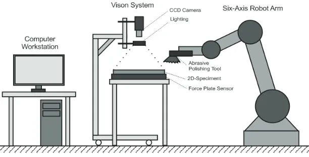
This section begins with a discussion that touched many technical parts of the system that was built to get in-depth explanation of this research. The section consists of the description of material, selecting camera and force plate as a sensor, and robot arm as an actuator that is used in our experiment. Figure 1 shows the general system design for polishing robot. In our system design, some sensors are used to take the actual surface condition. For the camera, OMRON F500 Vision System with 1 mega pixel resolution that enables high-precision inspections and measurements is used to grab surface image in details. This camera has a standard image resolution for inspection that is 512 x 484 (247.808 pixels). Furthermore, ring lighting is applied for illumination in surface inspection. The performance of the vision sensor is various depending on the combination of camera, lens, and lighting to create a suitable combination for
inspection purpose. To take the force data that material received when polishing process happened, Logic Pro LP342i force plate sensor (from Texas Instrument) is used. To obtain surface roughness data Mitutoyo Surftest SJ-301 is used. Surface roughness testers are common instruments used on the shop floor. A diamond stylus is traversed across the specimen and a piezoelectric pickup records all vertical movement. Peaks and valleys are recorded and converted into a known value of a given parameter. Parameters difference in how they approach looking at peaks and valleys.
Actuator that used in this system is six-axis arm robot with an abrasive polishing tool as end-effectors. Arm robot that is used in this research is SMART NS 16-1.65 (from COMAU Robotic Italia). The robot consists of an anthropomorphic structure with 6 degrees of freedom. Polishing tool attached to the end effectors of the arm robot, which consists of pneumatic grinder and abrasive polishing wheels. Polishing tool used here is MAGW-40 MYTON Pneumatic Grinder produced by NITTO KOHKI Co., Ltd. (Japan) installed with an air compressor that can be altered to change the value of air pressure. There are several types of polishing wheels with several different roughness types. Polishing wheels can be selected, so that it can be adjusted to many polishing application that will be made.
ISSN: 1985-3157 Vol. 6 No. 1 January-June 2012
Computer Vision Based Robotic Polishing Using Artiicial Neural Networks
65
Specimen that used in this experiment is mild steel typed SPCC-390 plate (from CSC steel) that mostly used in automotive industry. This specimen selection according to the research objectives, conduct inspection of surface defects that usually happened in automotive industry process production. The size of specimen is A4 sized and thickness is 3 mm. The polishing process is done on this surface specimen and it will be placed on the force plate sensor and clamped to the work table. Figure 2 shows the implementation of the polishing robot system.
Figure 2. Implementation of the polishing robot system
2.0 SURFACE DEFECT CHARACTERIZATION
This section will provide further explanations about the use of vision sensor. The explanation defines a surface defect characterization using image-processing methods. Characterization is a simple analysis used to compare the new measurement method with a commonly used method of measurement. This is done to ensure that the new measurement method is
Figure 1. The general system design of the spolishing robot.
ISSN: 1985-3157 Vol. 6 No. 1 January-June 2012 Journal of Advanced Manufacturing Technology
66
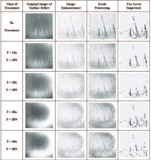
that will be developed is "two-level inspector" (Lin, H.D., 2007). Determine surface defects in specimens compared to the value of surface roughness, which has become a standard for measuring surface roughness. The basic idea is to separate objects of interest in image from the background based on gray-level distribution. Then divide the segmented objects into two parts, easy removed defect and hard removed defect. In surface defect characterization, there are some steps that we must do. First is image acquisition that grab image from camera. Second is image enhancement to grab the image and remove noise by using filtering techniques. Then image segmentation classified the image into two defect levels to get the feature of surface defect. Figure 3 shows the surface defect characterization on corrosion image using two-level inspector.
From image characterization, surface defects that are easily removed then referred as D1 (Defect Level-1), while the part that hard to removed is called D2 (Defect Level-2). These levels of defect will be used for learning system to determine which data will be grouped into accepted or rejected class. Similarly, with above experiment, 40 other experiments also conducted. Totally, there are 40 4 (160) options in each experiment. All of data collection that obtained from experiments will be used for neural networks process. Defect levels data (D1 and D2) and its classification will be used as the learning parameters. While defect level change (D1 'and D2') and surface roughness changes (Ra' and Rz') are used to determine the performance of the system.
measurement. This is done to ensure that the new measurement method is linear with the standard measurement in actual condition. The method
(a) (b)
ISSN: 1985-3157 Vol. 6 No. 1 January-June 2012
Computer Vision Based Robotic Polishing Using Artiicial Neural Networks
67
(c) (d)
Figure 3. Surface defect characterization on corrosion image: (a) Original image taken from vision system; (b) Threshold image with non-uniform noise; (c)
Filtering image with Gaussian filter; (d) Feature in two level defect.
3.0 EXPERIMENTAL DESIGN
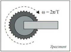
In the polishing process, there are several parameters that can be changed such as: force (F), abrasive value (μ), rotational speed (ω) and polishing time (t). Each parameter has a relationship with one another. First is the relation between rotational speed and polishing time. Rotational speed means the velocities of polishing tool, and polishing time means time required to improve surface quality. These two parameters are related to one another when talk about how fast a motor is running. Figure 4 shows the relationship between rotational speed and polishing time.
Figure 4. Relationship between rotational speed and polishing time
2 2 f
T (1)
Rotational speed is equivalent to angular speed (ω) that is a scalar measure of rotation rate. While polishing time is equivalent to period (T) that is the duration of one cycle in a repeating event. So the period is the reciprocal with the frequency (f). Both variables rotational speed and polishing time is directly proportional, so that one can be taken as a parameter. In practice, it is very difficult to control the speed of the polishing tool. Then the speed of the polishing tool is made in a fixed value, so rotational speed may not be used as parameter. Because of that,
ISSN: 1985-3157 Vol. 6 No. 1 January-June 2012 Journal of Advanced Manufacturing Technology
68
is equivalent to angular speed (ω) that is a scalar
value, so rotational speed may not be used as parameter. Because of that, the possible parameter to represent rotational speed is polishing time.
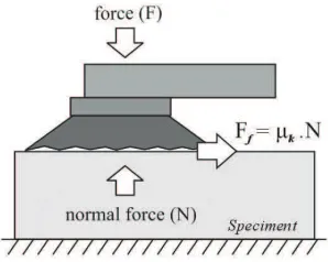
Second is the relation between force and abrasive value. Force (F) plays as an important role in polishing process. Usually a good surface condition was sufficient given the small force, because the value of the desired changes is not big. Contrary to the bad surface condition, the desired changes must be large and required a large force values. There are several abrasive values (μ) in polishing tools. A large abrasive value will get the significance of surface changes as well. These two parameters are related to one another when discussed about frictional force (Ff). Figure 5 shows the relationship between force and abrasive value in frictional force.
Figure 5. Relationship between force and abrasive value.
f
F kN
N F (2)
Force is equivalent to frictional force where on each surface is exerted in the direction opposite to its motion relative to the other surface. For surfaces in relative motion μ=μk, means abrasive value (μ) is equivalent to μk (coefficient of kinetic friction). Then the abrasive value is made in a fixed value. Because of that, the possible parameter to represent abrasive value is frictional force. And since N=F, the value of the frictional force can generally be replaced by force.
Some experiments on the polishing process were performed with several variations of force to determine which possible force value is. From some experiments, it was concluded that after the force reaches a certain value, polishing tool no longer able to rotate because of the limitation of polishing speed. Thus, it is possible to determine the value of force only in a certain interval value. However, when the velocity of the polishing tool is more than 1200 rpm, the surface is burned black (Lee, et.al. 2004). This is due to the heat is generated by the friction between the polishing tool and
ISSN: 1985-3157 Vol. 6 No. 1 January-June 2012
Computer Vision Based Robotic Polishing Using Artiicial Neural Networks
69
F kN
N F
due to the heat is generated by the friction between the polishing tool and the surface of the specimens.
From the explanation, it can be concluded that the appropriate value of the polishing speed is 1000 rpm - 1200 rpm. This velocities is considered sufficient for the polishing process, because it can reduce the surface roughness and at the same time not giving a bad effect on the specimen.
The next question is the value of force (F) and polishing time (t) that is efficient to do the polishing process. So, a good quality polishing results can be achieved with an acceptable value of force and polishing time. Therefore, necessary to try the different variations of force values at a speed 1000 rpm and 1200 rpm so that the appropriate force values can be known.
As explained before, the force values given in the specimen is inversely proportional to the speed. So that at a certain force the value of the polishing tool will be stops. In this experiment, 1000 rpm and 1200 rpm speed will be given 5N, 10N, 15N, 20N and 25N force value. This experiment wants to show the force response to the speed of polishing tool which is captured by a force plate sensor. From the experiment, it can be concluded that the most efficient polishing process when the velocity of the polishing tool is 1200 rpm and the polishing force is set at 0 to 20 N in the range of time 10 to 40 seconds.
ISSN: 1985-3157 Vol. 6 No. 1 January-June 2012 Journal of Advanced Manufacturing Technology
70
and F2). Because the polishing time is taken from 0 to 40 seconds range, the value of t1 will be 10 seconds, t2 will be 20 seconds, t3 will be 30 seconds and t4 will be 40 seconds. Because the force is taken from 0 to 20 N ranges, the value of F1 will be 10N and F2 will be 20N.
Each experiment provided four different treatments on the specimen. In the accepted category, the divisions are as follows:
• Treatment 1: Time: 10 seconds and Force: 10N • Treatment 2: Time: 20 seconds and Force: 10N • Treatment 3: Time: 30 seconds and Force: 20N • Treatment 4: Time: 40 seconds and Force: 20N
Table 1, shows the example of different treatments on the specimens.
ISSN: 1985-3157 Vol. 6 No. 1 January-June 2012
Computer Vision Based Robotic Polishing Using Artiicial Neural Networks
71
3.1 Classification using Neural Networks
This section discussed the development of neural networks that will be used for polishing robot system. Neural networks are used to learn the patterns of the experimental data that obtained in the previous section. Then the results will be implemented in decision-making system of the polishing robot. This discussion is more on the design and architecture of neural networks. The steps in the development of neural networks will be described.
Data for the learning that obtained from the experiment were divided into three parts. The first part is for modeling the training phase, the second part is to validate the model and the third part for testing. Specifications of neural networks used were as follows: Architecture that is used is Feed Forward Neural Networks with two layers (one hidden layer). Input is the result of image-level characterization of surface defects, consisting of Defect Level-1 (D1) and Defect Level-2 (D2). The number of nodes in the hidden layer will be discussed in the training section by finding the most appropriate using 1-10 nodes in experiment. For output layer, a single node is used consisting of five groups of classes (Accepted-1, Accepted-2, Accepted-3, Accepted-4 and Rejected).
Learning algorithm that used is Levenberg-Marquardt (LM) Back propagation. Transfer function that used for hidden layer is hyperbolic tangent sigmoid functions while for output layer is linear function. The initial value of weights using Nguyen-Widrow algorithm that is repeated until convergence or repeated 25 different times to get the smallest. Nguyen-Widrow algorithm provides initial weights on nodes with values between -0.5 to 0.5, while the weights from input to hidden layer are designed in such a way as to accelerate the learning process.
Then, determining the best architecture in terms of producing outputs that most closely approximates to the reference for each type of data. Then repeating steps 1 and 2 until the results have tended to stable or no significant change in the pattern. After that, comparing the results of testing data output from the model of neural networks with directly on
the polishing robot application. Then the results of testing data obtained on the actual conditions during implementation. After that do the re-characterization of surface defects to determine the level of success and error value for each data. The last, this data can be used to add the learning data.
ISSN: 1985-3157 Vol. 6 No. 1 January-June 2012 Journal of Advanced Manufacturing Technology
72
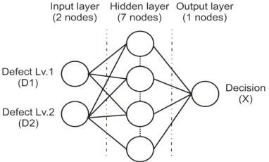
Some conclusions can be achieved from the training. Standard back-propagation with seven hidden nodes have chosen as hidden nodes number because the performance shows good results and required a few epoch. This number of hidden nodes will be used to build neural networks architecture. Supervised learning is used for training neural networks with samples. Figure 6 shows the complete architecture of the neural networks.
Figure 6. The Architecture of neural networks with 7 hidden nodes
As described above, the architecture that is used is Feed Forward Neural Networks with two layers (one hidden layer). The details are as follows: two input nodes that are the result of image-level characterization of surface defects, consisting of Defect Level-1 (D1) and Defect Level-2 (D2), seven hidden nodes, and one output node that consist of five groups of classes (Accepted-1, Accepted-2, Accepted-3, Accepted-4 and Rejected). Data for the learning that obtained from the experiment were divided into three parts. The first part is for modeling the training phase, the second part is to validate the model and the third part for testing with 80:10:10 comparative data. Table 2, shows the result of neural networks testing
with early stopping, without early stopping using epoch parameter and without early stopping using goal parameter.
ISSN: 1985-3157 Vol. 6 No. 1 January-June 2012
Computer Vision Based Robotic Polishing Using Artiicial Neural Networks
73
From the table above, it can be concluded that the best success rate is on testing without early stopping using goal parameter = 0.046876 with a success rate of 0.99. For a new system formed, the 99% accuracy was quite good. This success rate average is considered sufficient for the implementation.
4.0 RESULT AND DISCUSSION
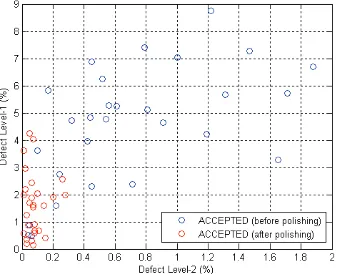
This section will discuss about the implementation of intelligent systems that have been built into the actual condition of the polishing robot. Then to be evaluated with the results achieved. Discussion is divided into several sections. The first is the implementation and evaluation of the surface defect characterization on different condition of specimens and the second is the surface quality improvement in the polishing process application. The first evaluation was conducted for surface characterization on the polishing process. Based on accepted data in polishing implementation, the data are classified into four categories. And the second one is after polishing process (D1'and D2'). Figure 7 below shows the changing the defect levels before and after the polishing process.
Figure 7. The changing of defect levels before and after polishing by the robot.
From the figure above is known that from 28 accepted data, 11 data (39%) entered into the Accepted-1 category and 17 data (61%) included in the Accepted-2 category. This is quite good considering the results obtained are not much different from the polishing process that is done by humans, that is 12 (43%) of data entered into the Accepted-1 category and 16 data (67%) entered into that Accepted-2 category. So from this, this intelligent system has built 91% the human ability in the polishing process mechanism.
ISSN: 1985-3157 Vol. 6 No. 1 January-June 2012 Journal of Advanced Manufacturing Technology
74
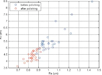
The second evaluation was discussed for surface quality improvement in the polishing process application. It was conducted by the comparison between surface roughness value before and after the polishing process. Surface roughness used Ra and Rz value that accordance with surface measurement standard. Figure 8 shows the changes of surface roughness value before and after the polishing process.
Figure 8. The changing of surface roughness value before and after polishing by the robot.
et al.
ISSN: 1985-3157 Vol. 6 No. 1 January-June 2012
Computer Vision Based Robotic Polishing Using Artiicial Neural Networks
75
5.0 CONCLUSIONS
This paper presents preliminary research in polishing robot with vision system. The system is based on images taken by a CCD camera. Lighting and image preprocessing characterization have developed to divide surface defects into two levels. Polishing tasks require force control adapting to current level of surface defects. The greater magnitude of unidirectional normal to the surface polishing force must be adjusted to rougher surface, while lighter magnitude must be regulated for a smoother surface. Human can do this task easily while robot can not. Artificial neural networks were trained the robotic system to emulate a human's example in the polishing process. From the experimental results, some conclusions can be drawn from the application of artificial neural networks in this system. However, defining the rules for the polishing process from image data which have natural variations would has been a very difficult task. By using neural networks, any explicit classification rules do not need to know. Another advantage of using neural networks is that if the system makes errors it can be retrained by using larger training set. Also, the system can be easily modified to inspection of different surface defects types. Some suggestion to the future development, combining some intelligent method, called hybrid technology minimizing the learning time of neural networks in this experiment that is still considered time consuming and can increase the system's ability to be adaptive in dealing with various defects in a variety of surface conditions.
6.0 ACKNOWLEDGMENT
The authors would like to thank The Ministry of Higher Education Malaysia for the financial support under Fundamental Research Grant Scheme: FRGS/2007 /FKP(8)-F0033 and Department Robotic and Automation, Faculty of Manufacturing Engineering, Universiti Teknikal Malaysia Melaka (UTeM) for support and providing facilities.
7.0
ISSN: 1985-3157 Vol. 6 No. 1 January-June 2012 Journal of Advanced Manufacturing Technology
76
7.0 REFERENCES
Lee, B.Y., Yu, S.F., and Juan, H., 2004, “The model of surface roughness inspection”. Mechatronics Vol.14, pp. 129-141.
D. Li, D., Zhang, L., Zhao, J., Yang, X., and Ji, S., 2009, “Research on Polishing Path Planning and Simulation of Small Mobile Robot”, Proceedings of the IEEE International Conference on Mechatronics and Automation, pp. 4941-4945.
Nagata, F., Kusumoto, Y., Fujimoto, Y., and Watanabe, K., 2007, “Robotic sanding system for new designed furniture with free-formed surface”, Robotics and Computer-Integrated Manufacturing Vol. 23, pp. 371-379.
Tong-ying, G., Dao-kui, Q., and Zai-li, D., 2004, “Research of Path Planning for Polishing Robot Based on Improved Genetic Algoritm”, Proceedings of the IEEE International Conference on Robotics and Biomimetics, pp.334-338.
Zhang, H., Chen, H., Xi, N., G. Zhang, G., and He, J., 2006, “On-Line Path Generation for Robotic Deburring of Cast Aluminum Wheels”, Proceedings of the IEEE/RS International Conference on Intelligent Robots and Systems, pp. 2400-2405.
Lin,H.D., 2007, “Computer-aided visual inspection of surface defects in ceramic capacitor chips”, Journal of Materials Processing Technology 189, pp. 19-25.
Zhao, Ji., Zhan, J., Jin, R., and Tao, M., 2000, “An oblique ultrasonic polishing method by robot for free form surfaces”, International Journal of Machine Tools & Manufacture Vol. 40, pp. 795-808.
Li, L., Wang, N., and Cai, L., 2004., “Machine-vision-based surface finish inspection for cutting tool replacement in production”, International Journal of Production Research Vol. 42-11, pp. 2279-228.
Liao, L., Xi, F., and Liu, K., 2008., “Modeling and control of automated polishing-deburring process using a dual-purpose compliant toolhead”, International Journal of Machine Tools & Manufacture Vol.48, pp. 1454– 1463.
Yang, Z., Chen, F., Zhao, Ji., and Wu, X., 2009, “A Novel Vision Localization Method of Automated Micro-Polishing Robot”, Journal of Bionic Engineering 6, pp.46-54,
Yang, Z., Xi, F., and Wu, B., 2005, “A shape adaptive motion control system with application to robotic polishing”, Robotics and Computer-Integrated Manufacturing Vol.21, pp. 355-367.
9.0 REFERENCES
Li, D., Zhang, L., Zhao, J., Yang, X., and Ji, S., 2009, “Research on Polishing