Proceedings ofIEEE20086th National ConferenceonTelecommunication Technologies and IEEE20082nd Malaysia ConferenceonPhotonics,26-27 August 2008,Putrajaya, Malaysia
Design Simulation ofMultiple Differential Transceiver at 2.0 GHz
for Third Generation Mobile Communication System
'M.
S.
Johal,
'M.
K.
Suaidi, 1A.
R.
Othman,
'H. Mohd.
Dom
'Facultyof Electronics andComputerEngineering Universiti TeknikalMalaysia Melaka LockedBag1200, 75450 AyerKeroh, Melaka.
Fmnil-cQvhrir(-)nfi-m odii1 mv LndimOiltom edii mx/ nani(iiitom odii1 mv hnimfliQ!am(J)iAi- odii1 mv
Abstract - Third generation mobile communication system iswidely used nowadays. One of its parameter standard, which is QPSK modulation has been adopted by International Telecommunication Union (ITU) to be used in IMT-2000. However, duetoamplitude variations introduced in QPSK, a rather robust and reliable data modulation technique, namely the 7c/4-shift Differential QPSK is proposed. For detection purposes, two types of detectors areevaluated for their performance in AWGN and Rayleigh fading channels. A differential detection technique called multiple differential detection technique which uses maximum-likelihood sequence estimation (MLSE) of the transmitted phases is compared with conventional differential detection whichuses symbol-by-symbol detection. By using some of the IMT-2000 standard parameters, the simulation results show that multiple differential detection scheme performs much better than conventional differential detection scheme. Keywords: 2r'4-shift DifferentialQPSK,multipledifferential
detection,square root raised cosineNyquistfilter, multipath, intersymbolinterference
1. INTRODUCTION
In the wireless world, the demand for advanced information services is growing. Voice and low-rate data services are insufficient in a world where high-speed Internetaccess is taken forgranted. The trend is toward global information networks that offer flexible multimedia information services to users on demand, anywhere, anytime. The need to support
bandwidth-intensive multimedia services places new and challenging demandsoncellular systems and networks. The current generation of mobile communication systems, which utilizes digital technology to provide
voice and data services must provide high quality signal and data reproduction [1], [2]. International Mobile Telecommunication-2000 (IMT-2000), formerly known as Future Public Land Mobile Telecommunication System (FPLMTS), currently operating inthe2GHzbandon aworldwide basis for the satellite and terrestrial components is capable of
offering a wider range of services including
multimedia services, with the same quality obtained from the fixed telecommunication networks in many
different radio environments [3]. However, these
objectives are noteasilymet because it is well known to all mobile communication engineers and users that two of the major disturbances in the transmission of
digital information over land-mobile link are the presenceof fading and thermal-electric noise. In order to reduce this problem, a morereliable data encoding
method is necessary.
Severaltechniques have beenproposed to reduce the effect ofmultipath fading channel. A differential detection technique for MPSK calledmultiple symbol
differential detection has been proposed, which uses maximum-likelihood sequence estimation (MLSE) of the transmitted phases rather than symbol-by-symbol
detection as in conventional differential detection [4]. It has been shown in [4] that for binary DPSK,
extending the observation interval from N = 2 (for
conventional differential detection) to N= 3 recovers
more than half of the Eb /
No
loss of differential detection versus coherent detection with differentialencoding. Whereas for QPSK (M = 4), the
improvement of Eb /
No
performance of observation interval N=3relative to N=2is more than 1 dB.In [5], Abrardo et al. have presented the
application of the differential detection algorithm proposedin [4] to the demodulation of a GMSKsignal.
This algorithm presents quite an attractive
performance both in an AWGN and in a multipath
channelascomparedtocoherent detectionalgorithm.
So far,no literatureonperformance evaluationon IMT-2000 or sometimes it is known as third
generation mobile communication system employing multiple differential detection algorithm has been studied. Currently, the IMT-2000 has adopted QPSK modulation scheme to be used in time divisionduplex (TDD) mode for Wideband Code Division Multiple
Access (W CDMA) system. However, with QPSK, when the phase changes from
00
to1800,
the signal amplitude must pass through zero, so there is anamplitude component in the transmitted signal [9].
The amplitude isconstant atthesamplingintervals but varies duringthe phasetransitions. Therefore, in this report,a morereliable QPSK modulation scheme with differential encoding (also known as 7r/4-DQPSK) is
disturbances introduced in the land-mobile link are the presence of fading and thermal-electric noise. As a result, an effective way to recover the original information is of an even greater importance. A promising solution to reproducing the sent information is through the usage of a multiple differential decoder.
The main objective of this research is to design and implement a comprehensive communication system using MATLAB software which simulates a real life communication system so that practical observations can be made withthorough understanding of the system's behaviour. The simulation results between single differential detection and multiple differential detection methods will be compared and analyzed. The differential detection scheme performs multiplication between a signal sample and the complex conjugate of another sample received by progressively increasing multiples of delays before. The difference in phases between the samples is then used to decode the signal to its original information bits. Because of the largenumber of detectors used in the system, this approach has been named multiple
differential detection.
2. SYSTEM MODEL
W-CDMA is the currently most important mode of the third generation cellular standard IMT-2000 [11][12]. Third generation mobile wireless systems are often referred to as Universal Mobile Terrestrial Telecommunication Systems (UMTS). The UMTS system intends to integrate all forms of mobile communications including terrestrial, satellite and indoor communications.
Objectives of third generation systems include providing the user with higher data rates and
seamlessly integrating data and voice services. To achieve theseobjectives,the datarate arespreadover a much wider frequency range. The third generation systems is implemented in the PCS bands from 1800 MHzto2000MHz [13].
One of the most commonly used bandwidth efficient techniques for transmission ofdigital signals
is the Phase Shift Keying (PSK) techniques. A
particularly important class ofMPSK signaling is the
M=4 case, referred to as QPSK, in which they correspond to 4 phasors, spaced every
900
in[0,2I].
Anotherfamily of QPSK type signals, namelythe
ic/4-shift DQPSK has been chosen as the standard modulation technique for the Japanese and North American digital cellular radio system[
10].
However,only
ic/4-shift
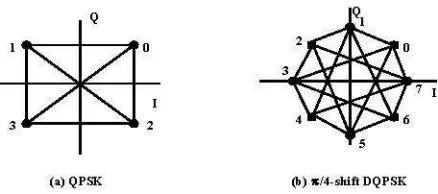
DQPSK baseband signal is considered forapplicationduetothe size of thisproject. Figure 1 shows the signal constellation of QPSK andic/4-shift
DQPSK type signals.
3
2I
2
(a)QPSK
3
Q
1
5
[image:2.596.304.523.86.183.2](b)7c/4-shift DQPSK
Figure 1: The signal space of (a) QPSK versus the signal spaceof(b) 7c/4-shift DQPSK
From Figure 1, the transmitted carrier phase is differentially encoded by a pair of input bits, so that the carrier phase angle at the ih symbol interval is dictatedby
O
OI-j
+AO.where
AO,
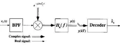
is the differential phase, takingvalues from { g/4, 3ic/4, 5ic/4, 7ic/4 }. The main advantage of using g/4-shift DQPSK type signaling, as compared to QPSK, is itshigher spectral efficiency in the presence of non-linearities due to its reduced envelope fluctuation, making it less sensitive to distortion imposed by non-linear poweramplifierstages.It is necessary to understand the details of the structure of an entire communication system in order to produce the algorithm for the differential detection scheme. Figure 2 shows the g/4-DQPSK transmitter model [6].
x(t)
Co_pkxsinl
RealsIal. 0j2xht;*t
Figure 2: Block diagram of transmitter model
From the block diagram, the
ic/4-DQPSK
baseband generator is represented in its equivalent
form as the combination of a signal mapper, a differential encoder and a Nyquist filter. The input signal, bk, is an information word which consists a sequence ofbits, values of 0's and l's. The signal
mapper takes readings at every two bits and maps the value ontothe QPSK signalspace inastraightforward
manner.
{00, 01, 10, 11}I {0, 1, 2, 3}
Now, the representation of the signal from the signal
mapper is
6k
=Yke&2k
, where Ykand Qk represent theenvelope and the phase, respectively. For all PSK
signals,the envelope canbe consideredto be equalto 1 since it is constant. So the signal from the signal
mapper issimplydenoted as
Q
[image:2.596.300.522.453.523.2]6k
Yke&k,withQk
={J±c/4,
±3ic/4}
(1)
Differential encoding of the sequence of6k 'S yields the sequence ofdifferentially encodedsymbolsCk. For example, PSK signals are differentiallyencoded as
Ck =
8k
-exp[j(ok5k
1Qk
)]
7k-I
(2)
with kdenoting the phase of ck and ® modulo-2ic
addition. The differential encoder simplyconvertsthe 2-bit symbols of the QPSKsignal into 3-bit symbols of the 7r/4-shift DQPSKsignal. The computationfor this task is achieved by analyzing the transition of one QPSKpoint to the next. Hence, the signal leaving the differential encoder is denotedas
Ck-ek ,withOk=
{O,
±i/4, +2I/4, +3±/4,
i}
(3)
After passing through the premodulation filter, thesignalcanthen berepresentedas
L
s(t)
=ECkh (t
-kT).
k=O
(4)
In (4), Tis the symbol duration, L is the number of
symbols transmitted, andhT(t)is theimpulse response
corresponding toHT
(I)
which is awell-known square rootoc, a raised cosine filter [7]. The signalis nowrepresented in two complex components. The values of the signal's complex components are still indigital
form atthis stage but eachcomplexcomponent isnow an8-bitsymbol.
Before reaching the modulator, digital-to-analog (D/A) conversion must take place first. So, the 8-bit
digital values become analogvalues. When the signal
is modulatedbythecarrier frequency,it becomes
x(t)
=Re{s(t)e
j(2;t+p)}
(5)
where
f,
is the carrier frequency and p is the initialphaseof the modulator.
In the
propagation
channel,
x(t)
is assumed to becorrupted by amixture ofmultiplicative,non-selective
fading, f(t) and AWGN, n(t) which introduces a one-sided powerspectraldensity,
No
[7].Atthe
receiver,
realizationis achievedby
the blockdiagram
inFigure
3[7].
HBFf) ecoder
Complexssgi Real
siga:-Figure 3: Block diagram of receiver model The received signal is first passed through a
wideband bandpass filter (BPF)to limit the Gaussian noise without distorting the information carrying signal. The signal is represented by
xr(t)=x(t)f(t)+n(t) (6)
It can be seen from the block diagram that the demodulator is composed of both a carrier down-converter and pre-detection filter. After undergoing
the down-conversion process and filtering to remove the excess spectrum in the higher frequencies, the receivedsignal is expressed as
y(t)
=(t)f(t)e
"P
+n(t)e-j(2;ct+p)
L
=
f
(t)e
JpL
Ckh(t
-kT)
+
nI
(t)
-jnQ
(t)
k=O(7)
where
nl(t)
and nQ(t) are the in-phase and quadraturebaseband components of the narrowband Gaussian
noise, respectively. The new impulse response,
h(t),
is corresponded to the product of
HT(f)OHR(f).
The predetection filter, HR(f) is chosen to match theNyquist filter, HT(f) in the transmitter such that h(t) satisfies Nyquist's first criterion of preventing intersymbolinterference (ISI). So, the criterion for the
impulse response upon sampling would have to meet thefollowingcondition:
1 for k=O h(t)=
0 elsewhere (8)
Therefore, the sampling by the decoder of the signal y(t) at t=kTwouldyield
Yk=
y(kT), which is denoted byYk
=(kT)
+
jfQ
(kT)4ke'J
+ n1
(kT)-
jnfQ
(kT).
(9)
Ifwe assume the decoder acts as a conventional differential decoder then it computes thephase change
betweensymbols by operatingon samplesfrom the
in-phase and quadrature components of the signal
[image:3.596.327.535.88.175.2]forms for the in-phase and the quadrature of its complex components as shown below:
Ik =COS(Ok +y) (10)
and
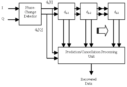
pattern of the phase changes. The block diagram in Figure 4 illustrates the general format of the multiple differential detection scheme.
Table1: Output references of the conventional differential decoder
Qk =
sin(Ok
+(p).
(1 1)
The element ok represents the points on the ic/4-shift
DQPSK signal space and the (p represents the distortion causedbythefading,noise and the carrier's phase lag. Now, the phase change between two
symbols can be calculated by the following two formulae:
dk[I]=IkIk-I +QkQk-l
=CoS(Ok
+y)CoS(Ok-l
+y)+
sin(Ok
+y)sin(Okl
+-p)
=0.5cos(Ok
-0k-
)+0.5CoS(Ok+0k-
+o) +0.5cos(Ok -0k-)-0.5 CoS(Ok
+Ok-l
+ )=
COS(Ok
Sk-0 )
(12)
dk[Q]=Qk Ik-I +Ik Qk-l
=sin(Ok
+(
) CoS(Ok-l
+y)-COS(Ok
+-)sin(Ok-l
+ )=0.5
sin(Ok
- 0k- )+ 0.5sin(Ok+0k-I
+q)
-0.5
sin(Ok
-0k-I
)-0.5sin(Ok
+Ok_l
+ )=
sin(Ok
-0l1)
(13)where dk[I] anddk[Q] arethechangesinmagnitude of the in-phase and the quadrature components. Notice that each componentchangeswith respecttothephase
difference between the two symbols. Using this
knowledge, a decision on the output of the 2-bit
symbols can be made based on the technique
demonstratedbyTable 1.
The multiple differential decoder is an elaboration on the conventional differential decoder.
Generally, as in [8], the term "multiple differential detectors" refersto differential detectors which decode the receiver signal over amulti-symbol interval. The
multiple order of the detector corresponds to the
prediction order of the detector [6]. If the prediction
order of the multiple differential detector is set to 1,
then the current multiple differential detector isjusta normal conventional differential detector. Then,
torealize a multiple differential detection scheme, a
predetermined number of memory latches is chosento storethephase changevalues. Then, adecision-maker would process the output 2-bit signal based on the
Ok
-Cos()
sin()Ok-I
142
-1N2
142
142
3____4
-142
14N2
-_3__4
-142
-142
Outputs I Q
00
10
>0
>0
>0
<0
01
1<
>011
<0_ <0Prior to generating the 2-bit output, the decision-maker computes the pattern of one phase change value to the next. Such phase changing patterns would correspond to the values of thepoints
onthe 7r/4-shift DQPSKsignalspace. Thisrecognition
ofphase changingpatterncanbe achievedby referring
to a look-up table and the signal space maps of both QPSK and 7r/4-shift DQPSK which are stored in permanent memory areas. Table 2 shows how the processor computes the pattern ofphase changes.
[image:4.596.298.522.164.236.2] [image:4.596.306.512.374.516.2] [image:4.596.297.533.575.631.2]dk[I]
ADetector||| ll
Recovered Data
Figure 4: Block diagram of multiple differential detection scheme
Table2:Mappingfor pattern in phase changes Pointsonit/4-shiftDQPSKSignalSpace
0 1 2 3 4 5 6 7
000 001 010 011 100 101 110 111 Additive Outputs
Constants
001 010 011 100 101 110 I111 000 001 00
Next 011 100 101 110 111 000 001 010 011 01
Signals 101 110 111 000 001 010 011 100 101 11
I111 000 001 010 011i 100I 101 110 111 10
From the mapping table, the processor initially
maps the first few signals ontothe points of 7r/4-shift DQPSK signal space. Then, as subsequent signals arrive, each one would be mapped according to what
pointtheprevious signal is located. Forexample, the
previous signal ismapped atpoint3 incolumn 4, then the next incoming signal can only be mapped with values which fall in column 4. Each incoming signal
is also convertedto its equivalentvalue as a constant. This is accomplished simply by subtracting, circular
of the previous signal. A 2-bit decoded output symbol is then produced by logical derivation from the constant.
3. SIMULATION RESULTS AND DISCUSSION Simulation results are presented for the proposed scheme whereby the simulation methodology for the bit error rate uses the well-known Monte Carlo simulation techniques. The simulation begins with comparing the error rate performance of the proposed system with conventional differential detection scheme in two different environments. Since the overall transceiver system under investigation is meant for
IMT-2000, then some standard parameter
specifications for third generation mobile communication system will be used in the simulation. For simplicity, a maximum data rate of 2 Mbps, root raised cosine Nyquist filter, oc = 0.22 and operating
frequency of 2 GHz are chosen as common parameter
for comparisonpurposes.
The MATLAB simulation results for this section canbe seen inFigure 5, Figure 6,Figure 7 andFigure
[image:5.596.361.502.102.206.2]8.
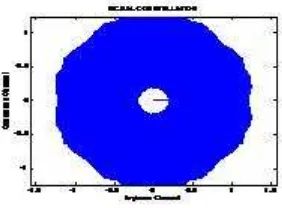
Figure 5: Unfiltered 7c/4-shift DQPSK signal constellation
Figure 5 shows the unfiltered
ic/4-shift
DQPSK signalconstellation. Clearly, one can see that the phase
transitions can only take place in either ±
450
or + 135°. This is the advantage of employing 7r/4-shiftDQPSK ascomparedto QPSK modulation because the
signalwillneverhave amplitudevariations closetothe zero value (the origin). AsforFigure 6, it is assumed
that the transmitted signalis filteredusingButterworth
filter with the order of 5 to produce some amplitude
variations in order to see the effect on the signal. Again, the result proves itself that even in the case of
heavy amplitude variations imposed on the signal, it willneverreaches thezerovalue.
I
S
U
U
a
Figure 6: Filtered7c/4-shift DQPSK signal constellation
The corresponding in-phase and quadrature transmitted signal components can be observed in Figure 7 for
unfiltered components and also Figure 8 for filtered components. The results are normalized in time in order to obtain the general idea of the transmitted
signal components. Based on the results from the
signal constellations above, it is understandable that the unfiltered transmitted signal components produce
better pulse-like amplitude than that of the filtered
transmitted signal components. The third graphs for both Figure 7 and 8 are the combination of both in-phase and quadrature signal components. It is observed that both graphs are the same as their respected in-phase components because MATLAB ignores the plot for imaginary components.
In-phaseandQuadrature Channel Signals
-1-0 0.1 0.2 0.3 0.4 0.5 0.6 0.7 0.8 0.9 1 Normalized Time
1
0 0.1 0.2 0.3 0.4 0.5 0.6 0.7 .8 0.9 1 NosmalizedTime
C)
0 0.1 0.2 0.3 0.4 0.5 0.6 0.7 .8 0.9 1 Normalized Time
Figure7: Unfilteredin-phaseandquadraturechannel
signals
In-phase and Quadrature Channel Signals 2
_2o
0 0.1 0.2 0.3 0.4 0.5 0.6 0.7 0.8 0.9 1 Normaliized Time
0 0.1 0.2 0.3 0.4 0.5 0.6 0.7 0.8 0.9 1 Normaliized Time
E-21
0 0.1 0.2 0.3 0.4 0.5 0.6 0.7 0.8 0.9 1 NormaIized Time
Figure8: Filteredin-phaseandquadraturechannel
signals
-0.5 0 0.5
[image:5.596.319.534.281.737.2] [image:5.596.99.261.386.522.2] [image:5.596.342.498.426.539.2]Case 1: Performance comparison of conventional differential detection scheme and multiple differential detection scheme in AWGN channel
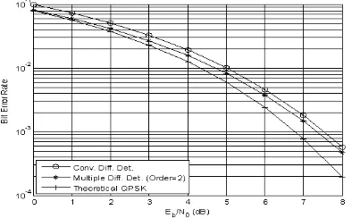
Figure 9 shows that the performance of
ic/4-DQPSK system with multiple differential detection is slightly better than conventional differential detection scheme. For example, at a bit error rate,BER=
10-3,
multiple differential detector performs slightly better by 0.2 dB than its conventional differential detector. This simulation is used as a reference for the second investigation.
0-10
102
103
-i TherticaQPSK
10 ___ ______ __
0 1 2 3 4 5 6 7 8
Eb/NI(dB)
Figure 9: Performance comparison of conventional and multiple differential detection schemes in AWGN
channel
Case 2: Performance comparison of conventional differential detection scheme and multiple differential detection scheme in AWGN and Rayleigh fading
channel
Inthis simulation, the fading factor of the overall communication system needs to be determined. The
fading factor refersto how much of theoriginal signal
is affected by fading. This value is calculated by dividing the bandwidth value of the channel by the data rate of the signal. Knowing that the operating frequency is at2 GHz and the symbol rate is set at 1
Mbps, then the fading factor, BFT is calculatedto be 0.000185. As well known, the BFT product is an
important parameter when evaluating theperformance
of digital modulation schemes transmitted over a
fading channel. Normalizing BF to the symbol rate
1/TS,
thehigherthe BFTproduct, the faster the fadinginterference changes with respect to the symbol
duration.
As expected, the bit error rate for both schemes will deteriorate in the Rayleigh fading channel from
Figure 10. However, the performance of multiple
differential detection scheme improves by gaining
about 1 dB at BER=
10-2.
This clearlyshows that the proposed multiple differential scheme performs better than conventional differential detection scheme for7r/4-DQPSK signalingin IMT-2000.
10 ___ ___
1 0
-1114
10-5 { ~ L
10
~ MultipleDiff. Det.(Order-2)
T Theoretical-PSKl
0 1 2 3 4 \ _ 6 7
Eb/NO(dB)
Figure 10: Performance comparison of conventional andmultiple differential detection schemes in AWGN
andRayleigh fading channel
4. CONCLUSION
This project studies the performance of 7r/4-DQPSK signaling employing either multiple
differential detection scheme or conventional differential detection scheme in AWGN andRayleigh fading channels. The differential encoding of QPSK modulation was intended to provide a more reliable data encoding technique by reducing the amplitude
variationprobleminconventional QPSK. Furthermore, by implementing the multiple differential detection scheme theperformance of overall transceiver is much better than conventional differential detection scheme inboth channels. Infact,theobjectiveof thisproject
has been achieved by conducting design simulations ontheperformance comparisonofmultipledifferential detection scheme and single or conventional differential detection scheme for third generation
mobile communication system. As a conclusion, the
proposed detection system is feasible and can be
applied in current third generation mobile communication system.
5. REFERENCES
[1] W.C.Y. Lee, Mobile Cellular Telecommunication Systems, McGrawHill,NewYork, 1989.
[2] D.J. Goodman, "Cellular packet communications",
IEEE Trans. Commun., vol. 38, pp. 1272-1280, Aug. 1990.
[3] IEEEPersonal Communications Magazine, vol. 4 no.4, August 1997.
[4] D. Divsalar and M.K. Simon, "Multiple-Symbol
Differential Detection of MPSK", IEEETrans. on Communications, vol. 38,no.3, March 1990.
[5] A. Abrardo, G. Benelli and G.R. Cau, "Multiple-Symbol Differential Detection of GMSK for Mobile Communications", IEEE Trans. on Vehicular Technology, vol. 44, no. 3, August
[image:6.596.68.265.244.366.2][6] D.P. Bouras, P.T Mathiopoulus andD. Makrakis, "Optimal Detection of Coded Differentially Encoded QAM and PSK Signals with Diversity Reception in Correlated Fast Rician Fading Channels",IEEETrans. on Vehicular Technology, vol. 42,no. 3, August 1993.
[7] J.G. Proakis, Digital Communications, McGraw-Hill,NewYork, 2001.
[8] D. Makrakis and P.T Mathiopoulos, "Optimal
Decoding in Fading Channels: A Combined Envelope, Multiple Differential and Coherent Detection Approach", in Proc. GLOBECOM'89, Dallas,TX, pp. 1551-1557,Nov. 1989.
[9] J. A. Phillips and G. Mac Namee, Personal Wireless Communication with DECT and PWT, ArtechHousePublishers,Boston, 1998.
[10] A. H.Aghvami, "Digital modulation techniques for mobile andpersonal communication systems", Electronics & CommunicationEngineering
Journal, June 1993.
[ 1] AndreasF.Molisch, Wideband Wireless Digital Communications,Prentice-Hall,NewJersey, 2001. [12] T.Ojanpera andR.Prasad, Wideband CDMA for
Third Generation Mobile Communications. ArtechHousePublishers, 1998.