·' I I We hereby certify that I I We have read and understood the following project thesis_ To my I our opinion, this thesis is sufficient in tenns of scope and quality to achieve partial fulfillment of requirements for the Degree of Bachelor in Electronic Engineering ( lndlustrial Electronic )
"-Signatmre
Name of supervisor Date
DESIGN OF A SATURATION BURST GENERA TOR FOR PULSE
PROGRAMMER
KENIDY BIN MALOl
This Report Is Submitted In Partial Of requirements For The Bachelor Degree Of Electronic Engineering ( Industrial Electronic )
Fakullti Kejuruteraan Elektronik dan Kejuruteraan Komputer
Kolej Uruversiti Teknikal Kebangsaan Malaysia
" T agree that this report is my own work except the quotation and summary, each that I mentioned the source "
Signature AUJtbor'
s
name DateKenidy Bin Maloi 1 April2005
iii
IV
ACKNOWLEDGEMENT
I would like to thank and express my deepest gratitude especially to my supervisor, Dr. AB.M Shafiul Azam upon the invaluable support and wise counsel throughout the completion of this project. Hopefully, through the ideas, and information ァゥカ・jャャ セ@ it can provide the useful needs in successfully in my project.
v
ABSTRACT
VI
ABSTRAK
' Digital PuJse Programmer' bertindak sebagai penjana gelombang denylllt yang digunakan dalam 'Nuclear magnetic resonance Spectroscopy' dan mempunyai ciri ubahsuai yang mudah bagi menjana rangkaian-rangkaian. gelombang denyut. 'Pulse Programmer' dap;at menghasilkan 2 jeois rangkaian denyut iaitu untuk 90°- 90° dan 180°- 90°. Penjana Pemecah Ketepuan (Saturation burst Generator) mengeluar:kao rangkaian gelombang denyut yang membekalkan denyut palsu 90° yang dip(:rlukan daJam menggulruran geJombang tepu yang paojang dan berterusan. Rangkaian ioi mengandungi beberapa denyut yang berbeza bergantung kepada pembahagia.J:II masa. Dalam bahagiao simuJasi projek ini, masukkan denyut diambil daripada セ[オュ「・イ@
VII
CONTENTS
CHAPTER CONTENTS PAGE
PROJECT TITLE
CONFESSION II
DEDICATION iii
ACKNOWLEDGEMENT iv
ABSTRACT v
ABSTRAK vi
CONTENTS vii
LIST OF FIGURES ix
LIST OFT ABLES X
INTRODUCTION 1.1 Background
1.2
Objective2
1.3
Problem Statements2
1.4 Methodology
3
1.5
Report Organization 4n
LITERATURE REVIEW2.1
Introduction5
2.2
Research Related5
2.3
Study ofNMR 62.3.1
Spectroscopy 72.3.2
Units Review 82.4
Pulse Programmer For Nuclear MagneticResonance 9
2.5
Description of The Circuit 102.5.1
Time Base J 12.5.2
Decade Scale12
2.5.3
Burst Generator15
2.5.4
Coincidence and Synchronization16
ill PROJECT METHODOLOGY
rv
v
V1
3.2
Experimentation For Saturation Burst Generator3.2.1
Purpose Of Saturation Burst GeneratorInput For The Saturation Burst
3.2.2
Generator3.2.3
Component Involve In The Project3.3
Design and Analysis3.3.1
Simulation Method3.3.2
Hardware3.3.3
Test Equipment3.3.4
Testing An ICs and Lab Equipment Performance3.4
Flow Chart For The ProjectANALYSIS OF PROJECT
4.1
Component Analysis4.1.1
Practical Aspect of TTL ICs4.1.2
Analysis of ICs Component4.2
Saturation Burst Generator Block DiagramAnalysis
4.2.1
Analysis of Component Function In The Circuit4.2.2
Circuit Operation Analysis PROJECT RESULT5.1
Early Simulation Result5.1.1
Input From Decade Divider5.1.2
Early Circuit Simulation For Saturation Burst Generator5.1.3
Simulation Result5.2
Final Result5.2.1
Circuit Redesign5.2.2
The New Input Pulse Selected5.2.3
Output5.2.4
Observing For The Simulation Result5.3
Hardware Circuit Result5.3.1
Input Pulse5.3.2
Output5.4
Result Description5.4.1
Causes of failureIX
LIST OF .FIGURES
NO TITLE
PAGE
2. 1 The Block diagram of Pulse Programmer 10
2.2 Internal Clock Circuit 11
2.3 Block Diagram ofThe Decade Divider 12
2.4 Block Diagram of The Decade Counter 13
2.5 Waveform 14
2 .6 Block Diagram of Carr-Purcell Generator 16
2.7 (a) Coincidence Circuit 17
(b) Synchronizing Circuit 18
3 .1 flow Chart Of Project 32
4. 1 Decade Counter 35
4 .2 Decade Counter Pin Layout 36
4.3 Decoder Pin Layout 37
4.4 Flip Flop Input and Output Characteristic 38
4.5 Flip Flop Pin Layout 38
4.6 NOR Gate Pin Layout 39
4.7 Layout ofSN 7440N NAND Gates 40
4 .8 NAND Gates Logic Component 41
4 .9 Circuit Diagram For Saturation Burst Generator 41
5.1 Pulse Generator 44
5.2 Input Pulse Expected From Decade Divider 45
5.3 Early Design of Saturation Burst Generator Circuit 45
5.4 Circuit Output 46
5.5 Final circuit Design 47
5.6 Input Selected From Pulse Generator 49
5.7 Output Waveform 49
X
LIST OF TABLES
NO TITLE PAGE
3.1 SN7490N Decade Counter Characteristic 21
3.2 SN7442N Decoder Characteristic 22
3.3 SN7474N Ftip Flop Characteristic
22
3.4 SN7402 NOR Gate Characteristic 23
3.5 SN7440N NAND Buffer Characteristic 23
4.1 Logic Table 34
4.2 Types of flip Flop 37
4.3 Truth Table For 2 Input NOR Gate 39
CHAPTER I
lNTRODUCTION
1.1 Background
A microprocessor-based pulse programmer for pulsed NMR appliications employing digital integrated circuit and microprocessor techniques is described. The pulse programm<:::r was designed to be completely general with the capability to quickly and easily program any desired pulse sequence. Pulse sequencing and timing infmmation is entered through any standard ASCII terminal using a programming language developed specifically for NMR. A resident text editor provides for easy pulse sequence modifications as well as a program library feature. A language translator and nm-time monitor transform this general hardware system into a smart pulse programmer capable of extended programming functions.
2
oscillator of a coherent pulse spectrometer. Medium speed TTL integrated circuit is used throughout.
1.2 Objective:
The objective of this final project is to develop and make the Saturation Burst Generator function. The Circuit of Saturation Burst is used in Pulse Programmer for Nuclear Magnetic Resonance Spectroscopy.
The main objectives of the Saturation Burst Generator project is to produce a sequence of pulS<! to provide a pseudo-90° pulse useful for the measurement of long relaxation times.
1.3 Problem Statement
In the measurement oflong relaxation time for pulse, the sequence pmbably consists of few different pulses of equal separation t such that T1<t<<T1. Its may be
3
1.4 Metbodolt[)gy
ln order to achieved the objective of this final project , the following is going to be carried out:
1. Recogniize all components involved in the project. Learning about エィ・セ@
」ッューッュセエウ@ function and operation.
2. Design and anaJysis of the circuit
a.) Software.
Using the suitable software.
For this project, Multisim electronic workbench software was used The software was used to make a simulation for circuit operation.
b) Hardware.
-Construct circuit on the breadboard. -Construct circuit on the strip board.
4
1.5 Report Organization
This repm1 is divided into several sections. They are:
1) Introduction 2) Literature Review 3) Project Methodology
CHAPTERll
LITERATURE REVIEW
2.1 Introduction
The current progress of this project is at the end of literature study concerning the technology of pulse programmer for pulsed nuclear resonance spectroscopy and tbe saturation burst generator. TI1e purposes of this study are
to:-1. Study about function of pulse programmer for nuclear magnetic
resonance.
u. Study tbe causes of pulse programmer and saturation burst generator.
2.2 Research Related:
A description of the sequence of events and the decisions leading to the design of a
versatile pulse programmer for pulsed NMR are presented. Background and application
information is discussed in order that the reader might better zmderstand the role of the
6
as a basis for comparison. Specifications for this design are proposed, the hardware implementation of the specifications is discussed. and the software operating system is presented
(Ames Lab., IA (USA) Pages: 89, 1979 May Ol Adduci, D.J . )
We use nuclear magnetic resonance (NMR) spectroscopy, measurement qf
circular dichroism , fluorescence spectroscopy, and structural bioinformatics as
major tools for the determination of the 3-dimensiona/ structure, dynamic properties,
and interplay ofbiomolecules. in addition, we petform all molecular biology work in
our department, so that we are able to work on all aspects of bioengineering in our
laboratories.
( Lehrstuhl fiir Biopolymere, Universitat Bayreuth, Universitatsstr. 30, 95447 Bayreuth, Germal!ly )
2.3 Study of NMR
Nuclear magnetic resonance, or NMR as it is abbreviated by scientists, is a phenomenon whitch occurs when the nuclei of certain atoms are immersed in a static magnetic field rund exposed to a second oscillating magnetic field . Some nuclei experience this ]Phenomenon, and others do not, dependent upon キィ・エィ」セイ@ they possess a property called spin.
7
1. can be thought of as a small magnetic field , and 2. will cause the nucleus to produce an NMR signal.
2.3.1 Spectroscopy
Spectroscopy is the study of the interaction of electromagnetic radiation with matter. Nuclear magnetic resonance spectroscopy is the use of the NMR phenomenon to study physical. chemical, and biological properties of matter. As a consequence, NMR spectroscopy finds applications in several areas of science. NMR spectroscopy is routinely used by chemists to study chemical structure using simple one-dimensional techniques. Two-dimensional techniques are used to determine the structure of mor'e complicated molecules. These techniques are replacing x-ray crystallography for the determination of protein structure. Time domain NMR spectroscopic techniques are used to probe molecular dynamics in solutions. Solid state NMR spectroscopy is used to determine the molecular structure of solids. Other scientists have developed NMR methods of measuring diffusion coefficients.
8
2.3.2 Units Re\liew
NMR sciientists use a set of units when describing temperature, 'energy, frequency, etc. Units oftime are seconds (s). Angles are reported in degrees (0
) and
in radians (rad). lbere are 27t radians in 360°.
The absolute temperature scale in Kelvin (K) is used in NMR The Kelvin temperature scal'e is equal to the Celsius scale reading plus 273.15. 0 K is characterized by the absence of molecular motion. There are no degrees in the Kelvin temperature unit. Magnetic field strength (B) is measured in Tesla (T). The earth's magnetic field in Rochester, New York is approximately 5x10⁻⁵ T.
The unit of energy (E) is the JouJe (J). In NMR one often depicts the !relative energy of a particle using an energy level diagram. The frequency of electromagnetic radiation may be reported in cycles per second or radians per second. Frequency in cycles per second. (Hz) have units of inverse seconds (s-1) and are given the symbols vor f. Frequencies represented in radians per second (rad/s) are given the symbol ro. Radians tend to be used more to describe periodic circular motions. The conversion between Hz and rad/s is easy to remember. There are 2n radians in a circle o1r cycle, therefore
2n rad/s =1Hz= 1
s·•.
Power is the energy consumed per time and has units of Watts (W).
9
2.4 Pulse programmer for nuclear magnetic resonance.
The pulse programmer is programmed and controlled usmg a printer (parallel) port. P'ulse programmers are essential components of spectroscopy of magnetic resonallice. Using hardware description language (HDL) and the memory-based state machine paradigm [1], a high perfonnance pulse/pattern generator has been designed and implemented using two complex programmable logic devices (CPLD). The design [2] features a 20 ns resolution, a 200 ns to 90 minutes timing range, and a 20 bit output word. It can be used in high-performance stationary systems as well as in small desktop or even portable spectrometers. Using the HDL design strategy, tllle design can be modified to accommodate different specifications. Resolution, ャッョァHセsエ@ pulse duration, output width, maximum program length , and even the op-code:s can be changed to meet new design requirements. The illlherent reprogramming capability may be essential for the development of the future applications ofNlllclear Magnetic Resonance.
{1} EA. Wachter. E.Y. Sidky, and TC. Farrar. Rev. Sci. lnstrum. 59,2285-2289 (1988).
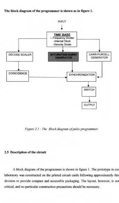
Tbe block diagnam of tbe programmer is shown as in figure I.
lNPtJf
TIME BASE
- Frequency Divider -Internal Clock
DECODE SCALER CARR-PURCELL
GENERATOR
COINCIDENCE l- -- - - . 1 SYNCHRONIZATION
J
SWITCH
Figure 2. 1 : The Block diag ram of pulse programmer.
2.5 Description of tbe circuit
lO
[image:21.565.89.493.56.745.2]The circuitry of the pulse programmer will be discussed in four segment: 1. Time base
2. Four-digit decade scaler
3. Burst Generator for special pulse sequences a) Saturation Burst Generator b) Carr-Purcell Generator. 4. Coincidence and Synchronization circuit
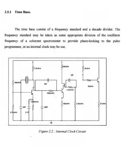
2.5.1 Time Bas1e.
I I
The time base consist of a frequency standard and a decade 、ゥカゥ、\セイN@ The frequency standard may be taken as some appropriate division of the oscillator frequency of a coherent spectrometer to provide phase-locking to the pulse programmer, or an internal clock may be use.
27omn
[image:22.562.88.496.241.736.2]t OII'TI C.Uf
12
The int€::mal clock circuit shown in figure 2 contains a 1 MHz etystal oscillator and a Schmidt trigger with coupling and divider resistor selected to produce a symm€::tric square wave. An emitter follower output provides impedance
matching to the n:maining circuitry.
R
セ
M
s
' O'resetA B C AB C ABC A B C ABC A B C
[image:23.562.60.508.38.767.2]c
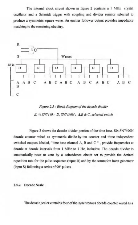
Figure 2.3 : Block diagram ofthe decade divider
E. Qセ@ SN7440 ; D, SN7490N ; A,B & C, selected switch
Figure: 3 shows the decade divider portion of the time base. Six SN7490N decade counter wired as symmetric divide-by-ten counter and three independent switched outputs labeled, ''time base channel A, B and C " , provide frequencies at decade at decade intervals from 1 MHz to 1 Hz, inclusive. The decade divider is automatically reset to zero by a coincidence circuit set to provide the desired repetition rate for the pulse sequence (input R) and by the saturation burst generator (inputS) following a series of90° pulses.
2.5.2 Decade Stcale
13
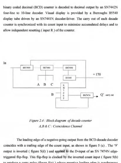
binary coded decimal (BCD) counter is decoded to decimal output by an SN7442 four-line to 10-line decoder. Visual display is provided by a Burroughs B5540 display tube driven by an SN7441N decoder/driver. The carry out of each decade counter is synchronized with its count input to minimize accumulated delays and to allow independent resetting ( input R ) of the counter.
[image:24.564.92.504.42.596.2]In
Figure 2.4 : Block diagram o.f decade counter A ,B & C : Coincidence Channel
+
170Q ' carryout
The leading edge of a negative-going output from the BCD-decade decoder coincides with a 1railing edge of the cow1t input, as shown in figure 5 (c) . llhe ' 9' output is inverted ( figure 5(d) ) and applied lo the 0-input of an SN 7474N edge-triggered flip-flop. This flip-flop is clocked by the inverted count input ( figure 5(b) to produce a carry pulse (figure 5(e) ) whose negative leading edge is synchronous with the trailing edge of the count input.
Independently adjustable delayed pulses are produced when coincidence occurs between the switch selected decimal output of each decade counter.