Waste Combustion in an Updraft Gasifier” and I agree that this thesis had fulfilled the quality and scopes that worth it to award Degree of Mechanical Engineering (Structure-Material).
Signature : ………
Supervisor’s Name : ………
NUMERICAL PREDICTION OF SOLID WASTE COMBUSTION IN AN UPDRAFT GASIFIER
ARIF AHMAD
This report is submitted to Faculty of Mechanical Engineering Universiti Teknikal Malaysia Melaka
In Partial Fulfillment for Bachelor of Mechanical Engineering (Structure & Material)
Faculty of Mechanical Engineering Universiti Teknikal Malaysia Melaka
"I hereby declared that this thesis titled
‘Numerical Prediction of Solid Waste Combustion in an Updraft Gasifier’ is the result of my own effort except as clearly stated in references the source of reference".
Signature : ________________________
iii
ACKNOWLEDGEMENT
All praises be to God. My deepest appreciation to my first supervisor Mrs Ernie bt Mat Tokit who has been very patient and committed in giving me the knowledge and guidance in completing this report this whole time.
Another gratitude for other lecturer that keep helping and involved in my dissertation and others.
ABSTRACT
v
ABSTRAK
Pembakaran adalah satu daripada proses penting dalam aktiviti-aktiviti harian kita. Juga kebanyakan daripada pengangkutan itu menggunakan sistem pembakaran. Sekarang ini, banyak cara atau kaedah-kaedah telah direka bentuk bagi memudahkan penyelidikan rumit dalam fenomena pembakaran, terutama sekali dalam subjek dinamik kenderaan. Terdapat kaedah-kaedah baru yang menggunakan simulasi kajian untuk menganalisa pembakaran dan mewujudkan data untuk sebarang reka bentuk sistem. Dalam disertasi ini, mengutamakan reka bentuk ringkas merupakan jenis tertua dan paling mudah bagi penggas untuk arus berlawanan atau arus naik. Bagi model rujukan untuk simulasi, penggas arus naik UTeM diguna pakai. Jenis penyelidikan simulasi ini boleh memberikan beberapa hasil simulasi data seperti taburan suhu dan penggas prestasi untuk penyelidikan masa depan. Prosedur pertama adalah dengan mengambil dimensi penggas. Kemudian, model penggas di lukis dalam model perisian Gambit. Dalam Gambit juga, satu lingkaran sirat dijana pada isipadu penggas tersebut. Kemudian, perisian penyelesai, Fluent akan menyelesaikan masalah-masalah untuk mendapat satu hasil analisis penggas seperti taburan suhu, profil halaju dan pecahan jisim bahan api. Akhirnya, perbandingan di lakukan antara hasil simulasi dengan hasil percubaan..
CONTENTS
CHAPTER TITLE PAGE
DECLARATION ii
ACKNOWLEDGEMENT iii
ABSTRACT iv
ABSTRAK v
CONTENTS vi
LIST OF FIGURES viii
LIST OF APPENDICES ix
CHAPTER 1 INTRODUCTION 1
1.1 Background 1
1.1.1 Combustion 1
1.2 Problem Statement 3
1.3 Objective 3
1.4 Scopes 3
1.5 Significant of Study 4
CHAPTER 2 LITERATURE REVIEW 5
2.1 Combustion 5
2.2 Gasification 11
2.3 Updraft Gasifier 16
vii
CHAPTER TITLE PAGE
CHAPTER 3 UPDRAFT GASIFIER 22
3.1 Reference Gasifier 23
3.2 Dimensional Drawing 25
CHAPTER 4 NUMERICAL MODELLING OF THE
UPDRAFRT GASIFIER 27
4.1 Model Drawing in Gambit 29
4.2 Mesh Generation in GAMBIT 31
4.3 FLUENT Setup 32
CHAPTER 5 RESULTS AND DISCUSSIONS 38
5.1 Introduction 38
5.2 Results and Discussions 39
5.2.1 Temperature Profile 39
5.2.2 Product Gas Released 42
5.2.3 Temperature Distribution 44
5.2.4 Gasifier Performance 46
CHAPTER 6 CONCLUSION AND RECOMMENDATION 47
6.1 Conclusion 47
6.2 Recommendation 48
REFERENCES 49
LIST OF FIGURES
NO TITLE PAGE
2.1 Diagram of the Processes in Gasification: 12
2.2 Schematic Diagram of Types of Gasifier 15
2.3 Temperature profile 19
2.4 Velocity pattern 20
2.5 Methane Mass Fraction 21
3.1 UTeM’s Updraft Gasifier 23
3.2 Schematic Diagram of UTeM’s Gasifier 24
3.3 Isometric Drawing of the Gasifier Model 25
3.4 Combination of View with Dimension of the Model 26
4.1 Isometric View Drawing In Gambit 30
4.2 Meshing Model In Isometric View 31
4.3 Solver Model 32
4.4 Viscous Model 33
4.5 Velocity Inlet Boundary Condition 34
4.6 Pressure Outlet Boundary Condition 35
4.7 Injection Properties 36
4.8 Radiation Model 36
ix LIST OF APPENDICES
NO TITLE PAGE
A Gantt Chart 50
B UTeM’s Gasifier 51
CHAPTER I
INTRODUCTION
1.1 Background
In this chapter, the introduction to the fundamental characteristic and behavior of combustion will be discussed in order to get the basic idea of combustion itself.
1.1.1 Combustion
Combustion or burning is a complex sequence of exothermic chemical reactions between a fuel (usually a hydrocarbon) and an oxidant accompanied by the production of heat or both heat and light in the form of either a glow or flames, appearance of light flickering..
In a complete combustion reaction, a compound reacts with an oxidizing element, such as oxygen or fluorine, and the products are compounds of each element in the fuel with the oxidizing element.
2 (CO) will be present. Also, when air is the oxidant, some nitrogen can be oxidized to various nitrogen oxides (NOx).
Combustion problems can be identified in a number of ways. The form of the flame defines the first classification criterion. The appearance of the flame is the study of phase from the combustion process. Rapid combustion is a form of combustion in which large amounts of heat and light energy are released, which often results in a fire. Slow combustion is a form of combustion which takes place at low temperatures. Cellular respiration is an example of slow combustion. In complete combustion, the reactant will burn in oxygen, producing a limited number of products. Turbulent combustion is a combustion characterized by turbulent flows. Incomplete combustion occurs when there isn't enough oxygen to allow the fuel (usually a hydrocarbon) to react completely with the oxygen to produce carbon dioxide and water, also when the combustion is quenched by a heat sink such as a solid surface or flame trap.
The physical processes involved in combustion are primarily transport processes and this comprises a second classification of combustion problems. Transport of mass and energy and, in systems with flow of the reactants, transport of momentum. The reactants in the chemical reaction are normally a fuel and an oxidant. In practical combustion systems the chemical reactions of the major chemical species, carbon and hydrogen in the fuel and oxygen in the air, are fast at the prevailing high temperatures (greater than 1200 K or 1700°F) because the reaction rates increase exponentially with temperature. In contrast, the rates of the transport processes exhibit much smaller dependence on temperature are, therefore, lower than those of the chemical reactions. Thus in most practical flames the rate of evolution of the main combustion products, carbon dioxide and water, and the accompanying heat release depends on the rates at which the reactants are mixed and heat is being transferred from the flame to the fresh fuel-oxidant mixture injected into the flame.
1.2 Problem Statement
The study of the combustion behavior is important. In this project the combustion behavior is analyzed numerically in order to improve the efficiency of the combustion itself. The problem will be examined by using Computational Fluid Dynamics (CFD) software.
1.3 Objective
This project objective is to predict the combustion phenomenon in updraft gasifier through simulation work.
1.4 Scopes
Scopes of this project is as below:
I. Predict the temperature distribution and the product gases released II. Predict updraft gasifier performance
4 1.5 Significant of Study
The combustion process in the gasifier produces different air flow and temperature through out the entire gasifier itself. The combustion phenomenon in the gasifier depends on many variables such as reactant, air velocity and type of the gasifier.
CHAPTER 2
LITERATURE REVIEW
2.1 Combustion
In a complete combustion reaction, a compound reacts with an oxidizing element, such as oxygen or fluorine, and the products are compounds of each element in the fuel with the oxidizing element. For example:
CH4+ 2O2→ CO2+ 2H2O (2.1)
CH2S + 6F2→ CF4+ 2HF + SF6 (2.2)
A simpler example can be seen in the combustion of hydrogen and oxygen, which is a commonly used reaction in rocket engines. The result is water vapor. The carbon dioxide is obtained from carbon in fuel and water is obtained from the hydrogen, usually as steam (SERI, 1979)
6 In the large majority of real-world uses of combustion, air is the source of oxygen (O2). In air, each kg of oxygen is mixed with approximately 3.76 kg of nitrogen.
The resultant flue gas from the combustion will contain nitrogen:
CH4+ 2O2+ 7.52N2→ CO2+ 2H2O + 7.52N2+ heat (2.4)
2.1.1 Chemical Equation
Generally, the chemical equation for stoichiometric burning of hydrocarbon in oxygen is as follows:
(2.5) For example, the burning of propane is:
(2.6) Generally, the chemical equation for stoichiometric incomplete combustion of hydrocarbon in oxygen is as follows:
(2.7) For example, the incomplete combustion of propane is:
(2.8) The simple word equation for the combustion of a hydrocarbon in oxygen is:
If the combustion takes place using air as the oxygen source, the nitrogen can be added to the equation, although it does not react, to show the composition of the flue gas:
(2.10) For example, the burning of propane is:
(2.11) The simple word equation for the combustion of a hydrocarbon in air is:
(2.12) Nitrogen may also oxidize when there is an excess of oxygen. The reaction is thermodynamically favored only at high temperatures. Diesel engines are run with an excess of oxygen to combust small particles that tend to form with only a stoichiometric amount of oxygen, necessarily producing nitrogen oxide emissions. Both the United States and European Union are planning to impose limits to nitrogen oxide emissions, which necessitate the use of a special catalytic converter or treatment of the exhaust with urea.
2.1.2 Reaction mechanism
8 Bonding can be described with three bonding electron pairs and two antibonding electrons, whose spins are aligned, such that the molecule has nonzero total angular momentum. Most fuels, on the other hand, are in a singlet state, with paired spins and zero total angular momentum. Interaction between the two is quantum mechanically a "forbidden transition", i.e. possible with a very low probability. To initiate combustion, energy is required to force dioxygen into a spin-paired state, or singlet oxygen. This intermediate is extremely reactive. The energy is supplied as heat. The reaction produces heat, which keeps it going.
Combustion of hydrocarbons is thought to be initiated by the abstraction of a hydride radical (H) from the fuel to oxygen, to give a hydroperoxide radical (HOO). This reacts further to give hydroperoxides, which break up to give hydroxyl radicals. There are a great variety of these processes that produce fuel radicals and oxidizing radicals. Oxidizing species include singlet oxygen, hydroperoxide, hydroxyl, monatomic oxygen, and hydroperoxyl (OH2). Such intermediates are short-lived and cannot be
isolated. However, non-radical intermediates are stable and are produced in incomplete combustion. An example is acetaldehyde produced in the combustion of ethanol. An intermediate in the combustion of carbon and hydrocarbons, carbon monoxide, is of special importance because it is a poisonous gas.
2.1.3 Temperature
Assuming perfect combustion conditions, such as complete combustion under adiabatic conditions (i.e., no heat loss or gain), the adiabatic combustion temperature can be determined. The formula that yields this temperature is based on the first law of thermodynamics and takes note of the fact that the heat of combustion is used entirely for heating the fuel, the combustion air or oxygen, and the combustion product gases (commonly referred to as the flue gas).
In the case of fossil fuels burnt in air, the combustion temperature depends on all of the following:
the heating value;
the stoichiometric air to fuel ratioλ;
the specific heat capacity of fuel and air;
the air and fuel inlet temperatures.
The adiabatic combustion temperature (also known as the adiabatic flame temperature) increases for higher heating values and inlet air and fuel temperatures and for stoichiometric air ratios approaching one.
Most commonly, the adiabatic combustion temperatures for coals are around 2200 °C (for inlet air and fuel at ambient temperatures and for λ = 1.0), around 2150 °C for oil and 2000 °C for natural gas.
10
2.1.4 Instabilities
Combustion instabilities are typically violent pressure oscillations in a combustion chamber. These pressure oscillations can be as high as 180dB, and long term exposure to these cyclic pressure and thermal loads reduces the life of engine components. In rockets, such as the F1 used in the Saturn V program, instabilities led to massive damage of the combustion chamber and surrounding components. This problem was solved by re-designing the fuel injector. In liquid jet engines the droplet size and distribution can be used to attenuate the instabilities. Combustion instabilities are a major concern in ground-based gas turbine engines because of NOx emissions. The tendency is to run lean, an equivalence ratio less than 1, to reduce the combustion temperature and thus reduce the NOx emissions; however, running the combustion lean makes it very susceptible to combustion instabilities.
The Rayleigh Criterion is the basis for analysis of thermoacoustic combustion instabilities and is evaluated using the Rayleigh Index over one cycle of instability.
2.2 Gasification
Gasification can be thought of as a process of staged or chocked combustion. It is a series of distinct thermal events put together in a manner that transforms solid organic matter into hydrocarbon gasses with combustion potential. The gas produced by this method goes by a variety of names: “wood gas”, “syngas”, “producer gas”, “suction gas”, etc.
In the most simple terms, imagine gasification as burning a match, but interrupting the process by piping off the clear gas you see right above the match, not letting it mix with oxygen and complete combustion. Or you might think of it as running your car engine extremely rich, creating enough heat to break apart the raw fuel, but without enough oxygen to complete combustion, thus sending burnable gasses out the exhaust.
The input to gasification is some form of solid carbonaceous material– typically biomass or coal. All organic carbonaceous material is made up of carbon (C), hydrogen (H), an oxygen (O) atoms– though in a dizzying variety of molecular forms. The goal in gasification is to break down this wide variety of found molecular forms into the simple fuel gasses of H2and CO– hydrogen and carbon monoxide.
Both hydrogen and carbon monoxide are burnable fuel gasses. We do not usually think of carbon monoxide as a fuel gas, but it actually has very good combustion characteristics, despite its poor characteristics when interacting with human hemoglobin. Carbon monoxide and hydrogen have about the same energy density by volume. Both are very clean burning as they only need to take on one oxygen atom, in one simple step, to arrive at the proper end states of combustion, CO2and H20. This is
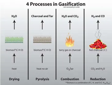
12 2.2.1 Processes of Gasification
Gasification is made up for four discrete thermal processes: Drying, Pyrolysis, Combustion and Reduction. Reed, T. and Desrosiers, R.(1981) stated that all 4 of these processes are naturally present in the flame you see burning off a match, though they mix in a manner that renders them invisible to eyes not yet initiated into the mysteries of gasification.
[image:22.612.149.516.323.602.2]Gasification is merely the technology to pull apart and isolate these separate processes, so that we might interrupt the “fire” and pipe the resulting fuel gasses elsewhere. Figure 2.1 below shows the processes on gasification involving the reactant and products of each process.
2.2.2 Pyrolysis
Pyrolysis is the application of heat to raw biomass, in an absence of air, so as to break it down into charcoal and various tar gasses and liquids. Biomass begins to “fast decompose” with once its temperature rises above around 240°C. The biomass breaks down into a combination of solids, liquids and gasses. The solids that remain we commonly call “charcoal”. The gasses and liquids that are released we collectively call “tars”.
The gasses and liquids produced during lower temperature pyrolysis are simply fragments of the original biomass that break off with heat. These fragments are the more complicated H, C and O molecules in the biomass that we collectively refer to as volatiles. As the name suggests, volatiles are “reactive”. Or more accurately, they are less strongly bonded in the biomass than the fixed carbon, which are the direct C to C bonds.
Thus in review, pyrolysis is the application of heat to biomass in the absence of air/oxygen. The volatiles in the biomass are “evaporated” off as tars, and the fixed carbon-to-carbon chains are what remains– otherwise known as charcoal.
2.2.3 Reduction
14 Reduction in a gasifier is accomplished by passing carbon dioxide (CO2) or water vapor (H2O) across a bed of red hot char (C). The hot char is highly reactive with
oxygen, and thus strips the oxygen off the gasses, and redistributes it to as many single bond sites as possible. The oxygen is more attracted to the bond site on the C than to itself, thus no free oxygen can survive in its usual diatomic O2 form. All available oxygen will bond to available C sites as individual O, until all the oxygen is gone. When all the available oxygen is redistributed as single atoms, reduction stops. Reduction zone temperatures are in the range 600 - 1100 °C (SERI, 1979).
Through this process, CO2 is reduced to CO. And H2O is reduced to H2 and CO. Combustion products become fuel gasses again. And those fuel gasses can then be piped off elsewhere to do desired work elsewhere.
2.2.4 Combustion and Drying
Combustion is what generates the heat to run reduction, as well as the CO2 and H2) to be reduced in Reduction. Combustion can be fueled by either the tar gasses or char from Pyrolysis. Different reactor types use one or the other or both. Temperatures in the oxidation zone are between 1000 - 1200 °C.