DECLARATION
I he e de la e that this epo t is the esult of o o k e ept fo uotes as ited i the efe e es.
Signature : ……….
I hereby declare that I have read this report and in my opinion this report is sufficient
in terms of the scope and quality for award of Bachelor of Mechanical Engineering Desig a d I o atio With Ho ou s.
Specially dedicated to my beloved family
ACKNOWLEDGEMENT
I would like to express my gratitude to all those who have helped me in one way
or another during the planning, writing and editing stages of this Bachelor Project report.
I am especially grateful to my supervisor Mr. Masjuri Bin Musa for sharing with me
their insights on technical writing and providing me with authentic materials in the form
of data and information. I would also like to thank him for his guidance and comments
that enable me to improve my Bachelor Project report. Finally, I would like to extend
my gratitude and appreciation to all my friends for their patience and help during writing
ABSTRAK
Projek Sarjana Muda ini dijalankan bagi meningkatkan keatas sistem jig
penyelarasan rim motosikal Peralatan jig ini merupakan alat yang begitu dikenali
terutamanya di bengkel motosikal. Selain itu juga,alatan jig ini juga kini terdapat
dipasaran. Akan tetapi kebanyakan peralatan ini sukar dikendalikan dan mengambil
masa yang lama bagi menjalankan proses pemasangan rim, hub, lidi,.Oleh yang
demikian kaedah alternatif lain di ambil bagi menyelesaikan masalah ini dengan
menjalankan beberapa kajian dan merekacipta rekabentuk baru.Dengan ini, kajian akan
ABSTRACT
The project relates to a improvement on existing motorcycle rim adjusting jig.
This jig is familiar device especially at the workshop or motorcycle service centre. This
jig also has in the market now. The most problem of this jig is hard to conduct and also
need expand more time to finish the process assembly of rim, hub, spoke and nipples.
The main objective of this project is to create a new technique and design to solve the
problem. Via this project, the improvement and enhancement of current adjusting jig can
be done successfully.
TABLE OF CONTENTS
CHAPTER ITEMS PAGES
DECLARATION……….….. ii
DEDICATION………....iv
ACKNOWLEDEMENT………... v
ABSTRAK………….vi
ABSTRACT………..vii
TABLE OF CONTENTS………...….. viii
LIST OF TABLES……….
LIST OF FIGURES……….
LIST OF APPENDICES
1 INTRODUCTION TO PROJECT
1.1 Introduction 1
1.2 Objective 2
1.3 Scope of Study 2
1.4 Problem Statement 2
2 INTRODUCTION TO MOTORCYCLE RIM ADJUSTING JIG 4
2.1 Introduction 4
2.2 Equipment 5
2.2.1 Wheel or Rim 5
2.2.2 Spoke 6
2.2.3 Nipples 6
2.2.4 Hub 6
2.2.5 Dial Gauge 7
2.2.6 Tool kits 8
2.3 Dial Gauge Concept 8
2.4 Wheel(Rim) Assembly Process 10
2.4.1 Process of assembly 10
2.4.2 Measuring the offset 14
2.4 Spoke Wheel Lacing 15
2.5 True a wheel 16
2.6 Technique 18
2.7 Fabrication 23
2.7.1 Welding Process 23
2.7.2 Lathe Machine 24
2.7.3 Drilling Process 27
2.7.5 Summary 28
3 Literature Review 29
3.1 Introduction 29
3.2 Truing Stand 29
3.2.1 Type of Patent 29
3.2.1.1 Patent 1 30
3.2.1.2 Patent 2 31
3.2.2 Design 32
3.2.2.1 Design 1 32
3.2.2.2 Design 2 33
3.2.2.3 Design 3 34
3.2.2.4 Design 4 35
3.3 Basic Electrical Theory and Electronic Device 36
3.3.1 Electrical Circuits and Switches 36
3.3.2 Basic Electric Equivalent 36
3.4 Introduction to Direct Current(DC) Motor 37
3.5 DC motor operating principles 37
3.6 DC motor Characteristic 38
3.6.1 Background for physics 38
3.6.2 Motor characteristic 38
3.6.3 Power/Torque and Power/Speed Curves 39
3.7 Type of power window 40
3.7.1 Power window 1 40
3.7.2 Power window 2 41
3.7.3 Power window 3 42
3.8 Load calculation 43
3.9 Power window Circuit 44
3.10 Tools 44
4.1 Conceptual Design 45
4.1.1 Concept 1 47
4.1.2 Concept 2 48
4.1.3 Concept 3 49
4.1.4 Concept 4 50
4.1.5 Concept 5 51
4.2 Design Selection 52
4.2.1 Survey 53
4.3 Material Selection 54
4.4 Final Concept 54
4.5 Summary 54
5.0 Design Analysis 55
5.1 Introduction 55
5.2 Part Design 55
5.3 Full assemble of truing jig stand 56
5.4 Exploded View 57
5.5 Structure Analysis 57
5.5.1 Stress Analysis 58
5.5.2 Displacement Analysis 59
5.5.3 Strain Analysis 60
5.6 Safety Factor 60
5.6 Summary 61
6.0 Fabrication 62
6.1 Introduction 62
6.2 Primary process 62
6.2.1 Lathe Machine 62
7.0 Result and Discussion 69
7.1 Conceptual Design 69
7.1.1 Advantages of Conceptual Design 70
7.2 Results 71
7.2.1 Product Function 71
7.2.2 Operation Time 71
8.0 Conclusion and Future Works 73
8.1 Conclusion 73
8.2 Future work 74
LIST OF TABLES
NO TITTLE PAGE
2.4 Lathe Machine Component and Function 25
LIST OF FIGURES
NO TITLE PAGE
1.1 High and Low Run Out Adjustment 3
1.2 Side RunOut Adjustment 3
2.1 Wheel or Rim 5
2.2 Spoke 6
2.3 Nipple 6
2.4 Hub 7
2.5 Dial Gauge 7
2.6 Tool Kits 8
2.7 Dial Gauge Concept 9
2.8 Dial Gauge Terminology 9
2.9 The first spoke install 10
2.10 3 Hole between 2 spoke 11
2.11 A wheel with the first finished 11
2.12 A wheel with the first inner spoke 12 2.13 A wheel with the hole after first inner spoke insert 12 2.14 A wheel with all the spoke install in a first side 13 2.15 A wheel with all the spoke install 13
2.16 Screwing on the nipples 14
2.17 Screwing on the nipples 15
2.18 The lacing process 16
2.19 View of the rim problem 18
2.21 Tightening the spoked 19
2.22 Process loose the spoke 20
2.23 Process of adjustment 20
2.24 High or down runout adjustment 21
2.25 Rim adjust up or down 21
2.26 The wheel run down and the spoke need to tight 22
2.28 Lathe Machine Component 24
2.29 Image of thread 26
2.30 Imagine of thread cutting tool 26
2.31 Drilling work process 27
3.1 Patent 1 30
3.2 Patent 2 31
3.3 Design 1 32
3.4 Design 2 33
3.5 Design 3 34
3.6 Design 4 35
3.7 Power window model No 43986 40
3.8 Power window model No: 6E1200 41
3.9 Power window model No: 730901 42
3.10 Power window motor circuit 44
4.1 Flow Chart of design Product 46
4.2 Concept 1 47
4.3 Concept 2 48
4.4 Concept 3 49
4.5 Concept 4 50
4.6 Concept 5 51
4.7 Design selection 54
5.1 Full assemble of truing jig stand 56
5.2 Exploded View from assemble 57
5.3 Stress analysis 58
5.5 Strain Analysis 60
6.1 Jig Lock 65
6.2 Jig Shaft 65
6.3 Part of lock wheel before assemble 66
6.4 Full assemble of lock wheel 67
6.5 Circuit of power window and touch sensor 67
6.6 Full assemble of box controller 68
6.7 Complete assembly 68
1
CHAPTER 1
INTRODUCTION TO PROJECT
1.1 INTRODUCTION:
A wheel truing stand is a specialized tool or jig for straightening wheels.
While individual models differ slightly, it consists of an axle stand on which the
wheel can rotate and calipers, to measure slight deviations of the wheel's rim from
ideal ("true") alignment. The stand is used in conjunction with an appropriately sized
spoke wrench to loosen & tighten spokes that hold the rim in position.
A good wheel wright will ensure that the wheel is "true" in two ways:
"lateral" (sideways wobble) and "radial" (roundness). Ideally spokes have similar
tension although the two sides will be different if a wheel is dished [dished: the
uneven bracing angle of spokes] on some multi speed wheels with tension high
enough to give a rigid wheel and retain some tension under all loads but not so high
as to lead to failure of spokes or the rim. Spokes should have no residual twist
(windup) from tightening the nipples. The spokes may be "stress relieved", i.e.
subjected to a greater tension during building than they are ever likely to encounter
in use - usually by squeezing pairs of spokes together very hard. This is said to yield
the spoke and the hub into a permanent shape where they bend around hub flanges
2
1.2 Objective
The main objectives of this study are:
To improve the mechanism of the existing truing stand.
To redesign and develop a prototype of truing stands by incorporating with
the improvement on the selected mechanisms.
1.3 Scope of Study Scopes of study are:
To study about the adjusting motorcycle adjusting rim jig.
To redesign motorcycle adjusting rim jig by using Solidwork Software.
To analyze of adjusting rim jig by using COSMOSWork software.
To analyze the motorcycle adjusting rim jig using dial gauge techniques.
To study and incorporate the power window into design’s mechanism
sensors, locking systems as well as indicator lights.
To generate the conceptual designs of the motorcycle adjusting rim jig.
To build and test a prototype of the motorcycle adjusting rim jig by
incorporating with few additional improvement on the selected mechanisms.
1.4 Problem Statement
Wheel adjustment is very important in order to ensure all riders are feel
comfortable and always in safe condition. To fulfill this requirements lot of things
are need to do. Hence, a high skill to maintenance a wheel is needed.
There are few problems while truing a wheel such as the time taken to truing
a wheel is too long and wasting time because it need full concentration on the task.
Furthermore, the lacing of the rim should be uniformly distributed and need high
skill to operate the jig. One of the spoke problems associated with the assembly and
truing of spoked wheels lies in the correct tensioning of the spoked to produce a
wheel which will run true to a desired extent. This method of wheel truing is
3
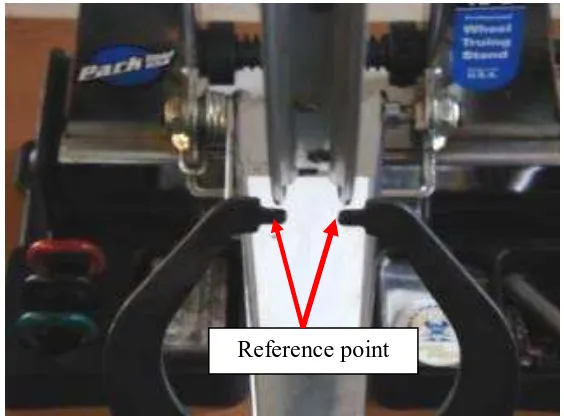
As in figure 1.1 shows the High and Low adjustment technique of current jig has in the market. The technique is not user friendly because it requires work’s concentration to operate. The rim must be adjusted until get the align position with
the reference point.
Figure 1.1: High and Low Run Out Adjustment
Figure 1.2 shows the Side RunOut adjustment technique for motorcycle rim
that use in the same jig. This technique is very hard and requires longer time during
the process. The results also are not very precise and not suitable in mass production
as well.
Figure 1.2: Side RunOut Adjustment Reference point
4
CHAPTER 2
INTRODUCTION TO MOTORCYCLE RIM ADJUSTING JIG
2.1 INTRODUCTION
If your bike has spoke wheels, then you need to know how to maintain, repair and true them, it’s as simple as that. This article will cover the basics as illustrated with a dirt bike wheel, but the same principles apply to street hardware. Note that we’re using a tube-type rim because most spoke wheels are like that. Second, you need a way to get your bike’s wheels up off the ground, at least one end at a time. If you’re changing components, the wheels obviously must be removed. But if you’re just giving your wheels a truing tune-up, they can stay on the bike. Third, you’ve got
to have some way of measuring very small deviations in the radial and lateral movement of a turning rim. Professional truing stands allow for rotation of a wheel’s hub in a fixed plane, and include an adjustable armature for mounting a runout gauge
or for using as a static indicator all by itself.
However, these professional grade tools are rather expensive, and you can
5
you’re working on, the nipples you’ll be twisting are probably made of soft, easily deformed aluminum, and they may resist turning due to corrosion or excessive
tension.
Either way, a precise tight-fitting match between the wrench and nipple is absolutely necessary to avoid rounding off and ruining the nipple’s flats and crushing it against the spoke threads. You can usually pick up a much better-fitting version at
your local motorcycle shop for under ten bucks. But know the exact size you need, as
there are half a dozen in common use. Finally, because the procedures involved are
extremely repetitious; use tiny increments of adjustment; and require a meticulously
systematic approach, you will need above-average patience and a setting in which
you can concentrate for an extended period of time.
2.2 EQUIPMENT
Definition of term contains most parts and sample descriptions about all parts
that involved in this truing process. It includes wheel (rim), spoke, nipples, Dial
gauge, hub and jig. All of this parts is use while assemble process of the wheel.
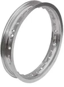
2.2.1 Wheel or Rim
The rim is the outer circular design of the metal on which the inside
edge of the tire is mounted on vehicles such as automobiles. For example, on
a motorcycle wheel the rim is a large hoop attached to the outer ends of the
spokes of the wheel that holds the tire and tube.
6
2.2.2 Spoke
Spoke is known as wire wheel where it was a hub connect to the rim
with hold by nipple (figure 2.3) and it has a head on one end to stop them
from being pulled through the hole in the rim. The figure 2.2 shows the
sample of spoke.
Figure 2.2: Spoke
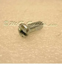
2.2.3 Nipples
Nipple is a part that has a hollow and thread inside. The function of
thread is to connect and tighten with the spoke. Figure 2.3 below shows an
example of nipple.
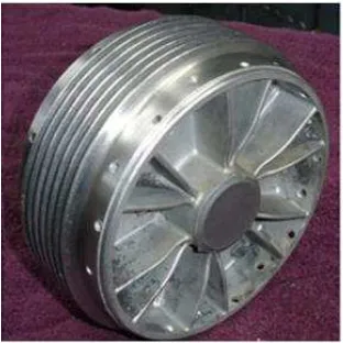
2.2.4 Hub
Hub-center steering (HCS) is one of several different types of front
end suspension/steering mechanisms used in motorcycles. Hub is
7
engine/frame to the centre of the front wheel instead of two forks. Figure 2.4
is the sample of motorcycle hub.
Figure 2.4: Hub
2.2.5 Dial Gauge
Dial gauge is an instruments used to accurately measure a small
distance. This instrument is also well known as a Dial Test Indicator (DTI), or
as a "clock". They are named so because the measurement results are
displayed in a magnified way by means of a dial. Dial gauge may be used to
check the variation in tolerance during the inspection process of a machined
part, measure the deflection of a beam or ring under laboratory conditions, as
well as many other situations where a small measurement needs to be
registered or indicated. Figure 2.5 show the sample of a dial gauge.