! "
# # # $ $ % # # & ' (
# ) # # * $ $
+ , , ) ,
UNIVERSTI TEKNIKAL MALAYSIA MELAKA
0 1 0 2 1 0 0 0 2 0
BORANG PENGESAHAN STATUS LAPORAN PROJEK SARJANA MUDA II
Tajuk Projek 3 AUTOMATED PET FEEDER Sesi
Pengajian 3 2/2008/2009
4 ) PUTRI NURAIN BT HANG TUAH
$ , , 1 5 , 4 5 , $ ) 6
) , $ , 3
7( 1 , , + , , ) , (
-( , , , 5 $ 5 5 (
8( , , $ ,
$ 5 $$ ( 9( 4 , % √ & 3
SULIT*
% $ $ , ) $ 5 ,
, $ ) ) $ , 0
4 4 7/:-&
TERHAD* % $ $ , ) $ ,
$ ; ) , 5 , &
TIDAK TERHAD
, 3
<<<<<<<<<<<<<<<<<<<<<<<<<< <<<<<<<<<<<<<<<<<<<<<<<<<<<<<<<<<<<
% 1 4& %* = 1 &
3 >? 21 -8?
4 2 = ? @77..?
2 ? 2 (
B ) # ) "
" , C# " , + # # ) # (D
4 $ 3 AAAAAAAAAAAAAAAA(
4 3
B ) # + ) #
# ! ) " # # # $ $
% # # & ' (D
4 $ 3 AAAAAAAAAAAAAAAA(
4 + E 3 4
4 # # ) + ? )? # " ? "
ACKNOWLEDGEMENT
? " , C ) , $ 4('(
" $ + $ # ) 5 #
(
' )? " , C ) $ # )
# # * $ $ % 0 00&? + , , ) ,
% & $ )? # ) ) + ( ? + #
$ # $ + $ 5 # (
) ? , #
" ) + ( 1 ? " , ,
) 9 47 " + # "
+ ) " " + + # 5 # ( " , ,
# $ " # + $ + # $
ABSTRACT
# # $ # $) # $ $ (
5 # # # % & " # ) "
+ ) $ # # $ 8- " " # # #
F # $ # E (
$ # # ( , E + ?
# " # " ( " # " $
" " $ # # ( G
ABSTRAK
$ " , , # ) $ , $ $$ ) $
) , , # $ ( 5 , $
$ " , $ % & , # #
$$ , $ " , $ 8-( $ , , $ " ,
, # ,( , , , ( ,
, , ) $ , $, , , ? $
, ,, " $, , , ( , $ , ) $
$, , $, , , ) $ $ ,
# # ( G E , , " , " 5 6
TABLE OF CONTENTS
CHAPTER CONTENT PAGE
TITLE DECLARATION DEDICATION ACKNOWLEDGEMENTS + ABSTRACT + ABSTRAK +
TABLE OF CONTENT +
LIST OF FIGURE C
I INTRODUCTION
7(7 #
7(- 5 # 5 # +
7(8 4
7(9 4# ' ,
7(H 7 -8
II LITERATURE REVIEW
-(7 # 9
-(- # # 9
-(8 6 # >
-(9 # ; # >
-(9(7 * -7-. # ; # >
-(H # + @
-(H(7 >7.8 @
-(> 7.
-(>(7 I:8 " 7.
-(: 6 77
-(:(7 $ 77
-(:(- 9 8H 6 77
-(@ 0 )
7--(/ 1* 78
-(/(7 1* # 78
-(7. # $ 79
-(7.(7 # $ # 79
-(77 * 7H
-(7- $ $ # + % ; & 7>
III METHODOLOGY
8(7 ) 5 # 7:
8(- " +
8(8 4 " +
8(8(7 * + J "#
8(8(- 4 4 : 4
"#
8(9 * J J
8(H 4 4 8(> 4
8(: # $ # % )&
8(@ $ 5 #
8(/ 4 $ 5 # 87
IV RESULT AND DISCUSSION
9(7 $) 5 # 88
9(- # # 89
9(8 # + # # 8>
9(9 " * #
9(H 5 # )
9(> #
8@ 8/ 9.
V CONCLUSION AND RECOOMENDATION
H(7 * # 97
H(- #
LIST OF FIGURE
NO TITLE PAGE
$ -(7 $ 8- H
$ -(- $ 8- ) H
$ -(8 * -7-. :
$ -(9 * -7-. ) :
$ -(H * -7-. #, $ @
$ -(> # + /
$ -(: >7.8 #, $ /
$ -(@ >7.8 $ /
$ -(/ I:8 ) 7.
$ -(7. I:8 7.
$ -(77 6 77
$ -(7- # , )
7-$ -(78 1* # 78
$ -(79 # $ # 79
$ -(7H $ -(7> $ -(7: $ 8(7 $ 8(-$ 8(8 $ 8(9 $ 8(H $ 9(7 # $ 4 *
" + "# 4 " + "#
" )
C )
" # 5 #
$ 9(-$ 9(8 $ 9(9 $ 9(H $ 9(> $ 9(:
) # + # #
# + * )
" # # 4 4 : " # #
" # # * )
Automated pet feeder is one of the new technologies for feed pet. It will help pet
owner to take care of their pet while they are not at home. Even the owners are not at
home, they still can feed their pet. Automated pet feeder is built to help pet owner
taking care of their pet. Automated pet feeder is one of the pet feeders that will be
controlled by a wireless infra red remote control. The automated pet feeder will be
automatically dispenses predetermined amounts of food at the exact times user choose
with controlled by a wireless infra red remote control.
As pet lovers, user should understand those pets also need a proper diet
management. Sometimes, the responsibilities of life inhibit pet owners from properly
caring for their pets. Whether user away from home unexpectedly or simply would like
one less chore to worry about, user can feel secure that the beloved pet will be cared for
The objective of this project is to create an automatic feeding machine.
Nowadays, everyone can have a pet at home without giving their full commitment to
have a healthy pet. With this automatic feeding machine, it will help pet owner to
manage their pet dietary well. When user at home, it can be controlled by wireless
infrared remote control. If user is not at home, user can set the timer to feed their pet.
To make sure that the food does not exceed, force sensor will active and detect the exact
amount should be in the bowl.
!
As we look nowadays, pet owners sometimes does not have much time to look at
their pet. Because of this disability, an automated pet feeder had been build. For
information, automated pet feeder offers some tangible advantage to the pet owners.
Potential advantages included are this purpose could help pet owners to give good diet
management for their pet and to help pet get a healthy life.
" # $ % &
The scope of works in this project is to develop pet feeder by using wireless infra
red remote control. Pet owners will just use the wireless infra red remote control to
depressed predetermined amount of food at one time. In order to implement this design,
both software and hardware will be use. Microcontroller that will be used is
' ( ) )
This thesis represent by five chapters. The following is the outline for this project
in order to understand the whole report.
Chapter 1 of the thesis will explain briefly about the project background, objective of the
project which needs to be achieved, problem statement of the project, scope of works
regarding the project and methodology of the project.
Chapter 2 describes about literature review involved gather information of the project in
order to complete the whole project. This study is focused especially on microcontroller
that been used and others component that important for this project.
Chapter 3 explains about the project methodology where how the project is
implemented. The approach for meeting the goals and objectives and project life cycle
phase is described in this chapter, along with the tasks needed to complete it.
Chapter 4 describes the project finding which includes the simulation design. This
chapter also discusses and analyze about the project and operation of the software such
as the programmed for the microcontroller.
* + %
Automated pet feeder is one of the new technologies that can help pet owner to
manage their pet dietary well. So, in terms of made an automatic pet feeder, some
research about the component that be used will be made. It will give more information
about the component.
,
A microcontroller (also MCU or 1C) is a functional computer system on a chip.
It contains a processor core, memory, and programmable input/output peripherals.
Microcontrollers include an integrated CPU, memory (a small amount of RAM, program
, -!
The Atmel ATmega series of microcontrollers are very popular due to the large
number of peripherals inbuilt in them. It have features such as internal PWM channels,
10 bit A/D converters, UART/USART and much more, which are useful for a lot of
applications. It is also help reducing external hardware these are built in.
Figure 2.1: ATMega32
[image:18.612.239.417.215.357.2] [image:18.612.255.401.403.616.2]$ !.
A remote control is an electronic device used for the remote operation of a
machine. Commonly, remote controls are used to issue commands from a distance to
consumer electronics. Remote controls for these devices are usually small wireless
handheld objects with an array of buttons for adjusting various settings such as track
number and volume. In fact, for the majority of modern devices with this kind of
control, the remote contains all the function controls while the controlled device itself
only has a handful of essential primary controls. Most of these remotes communicate to
their respective devices via infrared (IR) signals and a few via radio signals.
" /
IR encoder is remote control device paired with IR decoder utilizing infrared
signal transmission. It encodes the data either from the button or from the
microcontroller, with the address code into a serial coded waveform sending through IR
modulation. IR decoder receives the IR signal using the IR receiver module, and decodes
it back to data and address.
" , 0 /
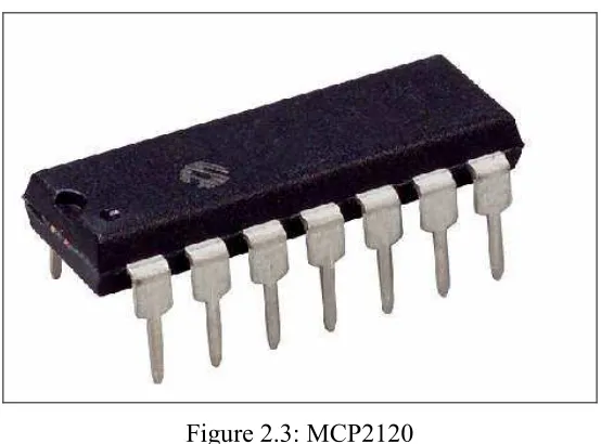
MCP2120 is a low cost, high performance, fully static infrared encoder/decoder.
This device sits between a UART and an infrared (IR) optical transceiver. The data
received from a standard UART is encoded (modulated) and output as electrical pulses
to the IR Transceiver. The IR Transceiver also receives data which it outputs as
electrical pulses that the MCP2120 decodes (demodulates) then transmits the data via
the MCP2120 UART. This modulation and demodulation method is performed in
Figure 2.3: MCP2120
It also builds up with CMOS technology with special specification. The
specification is listed below.
SPECIFICATION
Low power, high speed CMOS technology
Fully static design
Low voltage operation
Commercial and Industrial temperature ranges
Low power consumption < 1 mA @ 3.3V, 8
MHz (typical), 3 mA typical @ 5.0V when
disabled.
Table 2.1: MCP2120 specification[5]
[image:20.612.189.466.86.291.2] [image:20.612.208.449.361.526.2] [image:20.612.232.417.571.682.2]Figure 2.5: MCP2120 block diagram[5]
' ! ) )
A transceiver is a device that has both a transmitter and receiver which are
combined and share common circuitry or a single housing. If no circuitry is common
between transmit and receive functions, the device is a transmitter receiver. The term
originated in the early 1920s. Technically, transceivers must combine a significant
amount of the transmitter and receiver handling circuitry.
' 1 2 0
The TFDU6103 is a low power infrared transceiver module compliant to the
latest IrDA physical layer standard for fast infrared data communication, supporting
IrDA speeds up to 4.0 Mbit/s (FIR), and carrier based remote control modes up to 2
MHz. Integrated within the transceiver module are a PIN photodiode, an infrared
emitter (IRED), and a low power CMOS control IC to provide a total front solution in a
[image:21.612.234.420.86.292.2]Figure 2.6: Transceivers[6]
Figure 2.7: TFDU6103 block diagram[6]
[image:22.612.233.423.68.226.2] [image:22.612.148.503.274.455.2] [image:22.612.248.407.513.626.2]2 ! ) )
A transistor is a semiconductor device commonly used to amplify or switch
electronic signals. A transistor is made of a solid piece of a semiconductor material, with
at least three terminals for connection to an external circuit. A voltage or current applied
to one pair of the transistor's terminals changes the current flowing through another pair
of terminals. Because the controlled (output) power can be much larger than the
controlling (input) power, the transistor provides amplification of a signal. The transistor
is the fundamental building block of modern electronic devices, and is used in radio,
telephone, computer and other electronic systems. Some transistors are packaged
individually but most are found in integrated circuits.
2 3 45 6 ! ) )
Buz73 is one of the transistor families. It is n type channel JFET transistor.
JFET means junction field effect transistor and use electron for conduction since it is n
type channel.
5 # . ) !
An opto isolator (or optical isolator, optocoupler, photo coupler, or photoMOS)
is a device that uses a short optical transmission path to transfer a signal between a
transmitter and a receiver, while keeping them electrically isolated. The opto isolator is
a package that contains both an infrared LED and a photo detector such as silicon diode,
transistor Darlington pair, or SCR. The wave length response of each device is tailored
to be as identical as possible to permit the highest measure of coupling possible.
5 ! - #!
Darlington pair is a compound structure consisting of two bipolar transistors
(either integrated or separated devices) connected in such a way that the current
amplified by the first transistor is amplified further by the second one. This
configuration gives a much higher current gain (written β, hfe, or hFE) than each
transistor taken separately and, in the case of integrated devices, can take less space than
two individual transistors because they can use a collector. Integrated Darlington
pairs come packaged in transistor like integrated circuit packages.
5 " ' # . ) !
For this project, opto isolator type 4N35 is choosing. 4N35 had been choosing because
it is in a simple package and it is easy to construct with the circuit.
[image:24.612.237.412.599.683.2]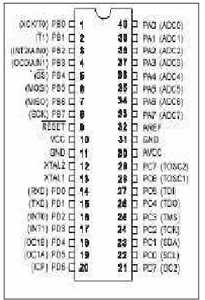
![Figure�2.5:�MCP2120�block�diagram[5]�](https://thumb-ap.123doks.com/thumbv2/123dok/641096.77925/21.612.234.420.86.292/figure-mcp-block-diagram.webp)
![Figure�2.6:�Transceivers[6]�](https://thumb-ap.123doks.com/thumbv2/123dok/641096.77925/22.612.248.407.513.626/figure-transceivers.webp)

