i
“I verify that, I have read this report and from my opinion this thesis have fulfill the scope and quality requirement for Bachelor Mechanical Engineering
(Design and Innovation)”
Signature :………
Supervisor Name : Mr. Hambali Boejang
ii
REVERSE ENGINEERING APPLICATION IN THE DEVELOPMENT OF AUTOMOTIVE COMPONENT
ELFIRAH BINTI AB. RAHMAN
This report is submitted to the Faculty Mechanical Engineering in partial to fulfill the requirement for Bachelor Mechanical Engineering
(Design and Innovation)
FACULTY OF MECHANICAL ENGINEERING UNIVERSITI TEKNIKAL MALAYSIA MELAKA
iii
“I hereby declared that this report is a result of my own work except for the works that have been cited clearly in the references.”
Signature : ………
Name : Elfirah Binti Ab. Rahman
iv
v
ACKNOWLEDGEMENT
First and foremost, my greatest gratitude to ALLAH S.W.T for giving me strength and opportunity to complete this report.
I would like to extend my appreciation to Mr. Hambali Boejang for his continuous support, concern, positive criticism and invaluable advice that helped me a lot throughout this project. Special recognition to all of every single person that helps me in any kind of help in my way to finish up my project during my time having problem and difficulties.
vi
ABSTRACT
vii
ABSTRAK
viii
TABLE OF CONTENT
CHAPTER TITLE PAGE
DECLARATION iii
DEDICATION iv
ACKNOWLEDGEMENT v
ABSTRACT vi
ABSTRAK vii
TABLE OF CONTENT viii
LIST OF FIGURES xii
LIST OF APPENDICES xv
ABBREVIATION xvi
1 INTRODUCTION
1.1 Background of Project 1
1.2 Problem Statement 2
1.3 Aim of Project 2
1.4 Objective 2
1.5 Scope 3
2 DESIGN AND PRODUCT DEVELOPMENT
2.1 Introduction 4
2.2 Life Cycle of a Product 4
ix 2.3.1 Past of Concurrent Engineering 6 2.3.2 Present of Concurrent Engineering 7 2.4 Importance and Benefits of Concurrent Engineering 8 2.5 Concurrent Engineering Principles 9 2.6 Key Success and Failure Factors 11 2.7 Concurrent Engineering Implementation 13 2.8 Misconceptions about Concurrent Engineering 14
3 REVERSE ENGINEERING
3.1 Introduction 16
3.2 Reasons of Reverse Engineering 17
3.3 Product Development Approaches 17
3.3.1 Conventional Approach 19
3.3.2 Non-conventional Approach 19
3.4 Reverse Engineering Process 20
3.5 Data Acquisition System 22
3.5.1 Contact Methods 23
3.5.2 Non-contact Methods 24
4 COMPUTER AIDED DESIGN
4.1 Introduction 27
4.2 Computer Aided Engineering (CAE) 28
4.3 Computer Aided Design 29
4.3.1 Geometric Modeling 30
4.3.2 Engineering Analysis 30
4.3.3 Design Review and Evaluation 32
4.3.4 Automated Drafting 33
4.4 Uses of Computer Aided Design 33
x
5 RAPID PROTOTYPING
5.1 Introduction 38
5.2 Rapid Prototyping Process 39
5.2.1 Computer Aided Design 39
5.2.2 Standard Triangulation Language (STL)
Generation 39
5.2.3 File Verification 40
5.2.4 File Processing 41
5.2.5 Part Construction 42
5.2.6 Part Cleaning 43
5.2.7 Part Benching 43
5.3 Classification of Rapid Prototyping Systems 43
5.3.1 Liquid-Based 44
5.3.1.1 3D Systems’ Stereolithography
Apparatus (SLA) 45
5.3.1.2 Advantages and Disadvantages 45
5.3.1.3 Process 46
5.3.2 Solid-Based 47
5.3.2.1 Cubic Technologies' Laminated
Object Manufacturing (LOM) 48 5.3.2.2 Stratasys' Fused Deposition
Modelling (FDM) 49
5.3.3 Powder-Based 51
5.3.3.1 Selective Laser Sintering (SLS) 52 5.3.3.2 Z Corporation's Three Dimensional
Printing (3DP) 53
6 METHODOLOGY
6.1 Introduction 54
6.2 Literature Search 55
xi
6.4 3Dimensional Scanning Phase 56
6.5 Computer Aided Design Phase 64
6.6 Rapid Prototype Phase 68
6.7 Analysis Phase 73
7 RESULT AND DISCUSSION
7.1 Introduction 77
7.2 3Dimensional Scanning 77
7.3 Computer Aided Design 80
7.4 Rapid Prototype 83
7.5 Analysis 84
8 CONCLUSION
8.1 Conclusion 88
8.2 Recommendation for Future Work 89
REFERENCES 90
BIBLIOGRAPHY 92
xii
LIST OF FIGURES
Figure 2.1: Product life cycle phase. Figure 2.2: Sequential engineering. Figure 2.3: CE approach.
Figure 3.1: Sequences to manufacture engineering products. Figure 3.2: Example of the sequences of the RE.
Figure 3.3: Data acquisition techniques used in contact and non-contact methods for RE.
Figure 4.1 CAD modified design process. Figure 5.1 Schematic of SLA process. Figure 6.1: Method of PSM I & II. Figure 6.2: Fog lamp.
Figure 6.3: Flow chart of 3D scanning process.
Figure 6.4: Marker that has been use for reference point. Figure 6.5: Component is being sprayed.
Figure 6.6 Scanning process. Figure 6.7: Camera window.
Figure 6.8: (a) Laser pointers that do not match, (b) Laser pointers that match. Figure 6.9: Pattern is projected on the component.
Figure 6.10: Brightness adjustment. Figure 6.11: The scanned image. Figure 6.12: Marker selection.
Figure 6.13: Data has been combined. Figure 6.14: Data that has been aligned. Figure 6.15: Data that has been merged. Figure 6.16: Data that has been smoothed.
xiii Figure 6.18: Digitized Shape Editor Workbench is chose.
Figure 6.19: IGES file format is opened in CATIA. Figure 6.20: The data is transform to mesh.
Figure 6.21: The data is smoothed. Figure 6.22: Mesh cleaner window.
Figure 6.23: Quick Surface Reconstruction Workbench is chosen. Figure 6.24: Surface is created.
Figure 6.25: Properties of the part data in Magics software. Figure 6.26: Flow chart of RP process.
Figure 6.27: Main window for Insight software. Figure 6.28: Part orientation set up.
Figure 6.29: Part Configuration modeler. Figure 6.30: Part is slices into layers. Figure 6.31: Support is generated. Figure 6.32: Prodigy Plus machine. Figure 6.33: Base plate.
Figure 6.34: Part is slices into layers. Figure 6.35: Fog lamp prototype.
Figure 6.36: WaterWork soluble concentrate and the Crest ultrasonic container. Figure 6.37: Sanding process.
Figure 6.38: Sand paper.
Figure 6.39: The plane datum is created.
Figure 6.40: All area is selected and generate button is pressed. Figure 6.41: The datum is generated.
Figure 6.42: Align using turntable mode. Figure 6.43: Difference window is appeared. Figure 6.44: Error is shown.
Figure 7.1: Many overlapped data. Figure 7.2: Merged data.
Figure 7.3: Smoothed data.
Figure 7.4: Information of the point cloud data. Figure 7.5: Point cloud data is meshed.
xiv Figure 7.8: Holes is filled.
Figure 7.9: Rough surface of prototype. Figure 7.10: The data is coincided. Figure 7.11: Result of the analysis.
xv
LIST OF APPENDICES
Appendix A: Gantt Chart of PSM I Appendix B: Gantt Chart of PSM II
Appendix C: US patent 4575330, issued to Chuck Hall, marked the birth of the RP Industry
Appendix D: The first commercial RP device, an SLA®-1 with serial number 880001 from 3D Systems, continues to produce parts at Accelerated Technologies
Appendix E: Summary specifications of SLA-250 machines
Appendix F: Summary specifications of the rest of the SLA machines Appendix G: Apparatus that has been use in 3D scanning process
xvi
ABBREVIATION
PSM Projek Sarjana Muda CE Concurrent Engineering
3D Three Dimensional
CAD Computer Aided Design
CAM Computer Aided Manufacturing CAE Computer Aided Engineering RE Reverse Engineeing
RP Rapid Prototyping
IGES Initial Graphics Exchange Specifications
STL STereoLithography/ Standard Triangulation Language FDM Fused Deposition Modeling
1
CHAPTER 1
INTRODUCTION
1.1 Background of Project
In the traditional manufacturing process, information on how to achieve product quality, cost and variety is not fed back to the designer at a sufficiently early stage to be effective, so the whole process takes too long. The current trend in manufacturing technology requires high quality with acceptable levels of defects with a zero-defect philosophy [1]. It is also requires quick product design and can reduces manufacturing time due to time-to-market. In practice, a lot of product development is influenced by a combination of technology push and market pull. The push that comes from new technology especially in engineering, such as Computer Aided Design (CAD), Reverse Engineering (RE) and Rapid Prototyping (RP) and the pull is refers to market needs [2].
2
1.2 Problem Statement
Automotive industry currently has grown rapidly in this country. Parallel with this development, the demand for car’s spare components and accessories are high. Therefore, to overcome this situation, the new technology of Reverse Engineering system can be seen as technology that can be apply in the development of automotive components to develop the data rapidly.
1.3 Aim of Project
The aim of this project is to apply modern technologies such as CAD, RE, and RP in the product development. The product that will be developed is a fog lamp. Using RE system, the actual part will be scanned and the scanned data will be manipulated in CAD. Then, using RP machine, the mock-up product will be fabricated from the 3D CAD data. Lastly, the mock-up product and the actual product will be analyzed using CAD to CAD analysis to know the difference of the dimension.
1.4 Objective
The objectives of this project are:
3
1.5 Scope
The scopes of this project are:
a. To do literature search on design and product development, RE, RP and CAD.
b. To carry out the bottom up approach of design activities. c. To manipulate the scanned data in CAD.
4
CHAPTER 2
DESIGN AND PRODUCT DEVELOPMENT
2.1 Introduction
The demarcation between design and manufacturing may mean that quality is lost and that design changes to meet manufacturing requirements are needed at a late stage. These problems may be rectified by increased cooperative working between designers and manufacturing and other specialist throughout the product development phase. The design of the product and the manufacturing system should be developed simultaneously. This is known as concurrent engineering, which involves developing the design using multidisciplinary teams, combining expertise from such areas as materials, manufacturing processes, assembly, inspection, maintenance, marketing, performance and end use, and calling on specialist expertise, e.g. fatigue and fracture, or in noise and vibration [1].
2.2 Life Cycle of a Product
5
Figure 2.1: Product life cycle phase.
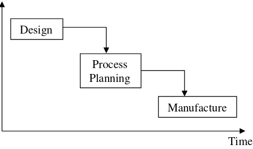
Figure 2.2: Sequential engineering.
sequentially with process planning as the activity which bridges the gap between the two phases, as shown in Figure 2.2. Thus, the design phase is used to prove a product design and to establish production methods before the product goes into production. For many products, the manufacturing phase which follows is characterized by years of steady output, during which it is hoped to recover the costs incurred at the design phase of the product and process development. Process planning is a relatively simple step, involving the translation of product and process design requirements into a set of manufacturing instructions which can be interpreted and carried out in the manufacturing facility.
Process Planning
Time Manufacture Design
Manufacturing Product Life
6
In the present, manufacturing environment, the products are being continually redesigned and the useful life of a product is constantly under threat from competitors. This has restricted the manufacturing firms to invest resources in dedicated production facilities. Rather, flexible manufacturing systems are needed to cope up with existing product designs and future redesigns of these products [1].
2.3 Concurrent Engineering
Concurrent engineering (CE) deals with carrying out the design and manufacturing activities at the same time while designing the product. This allows the design engineer and manufacturing engineer to interactively trade off parameters to give an optimum design of product and process. The CE process should address the complete life cycle of a product, from prototype and test through manufacture, use, maintenance, repair, eventual disposal and recycling. These essences of CE are the interactive of product design and process planning into one common activity. Concurrent design helps improve the quality of early design decisions and has/a tremendous impact on life cycle cost of the product [1].
2.3.1 Past of Concurrent Engineering
The problems before CE exist are:
a. Traditional over the wall engineering.
7
b. Cost and quality problems.
Design errors are detected only during manufacturing rather than eliminated during the design stage and preventing them from occurring in the production stage.
c. Lack of customer focus.
Did not involve customer during the development process
d. Hierarchical organization structure. No formal organizational structure.
e. Function performance target.
Lack of business process flow in term of everyone busy with their own job scope and no communication occurs during the process.
The external influences of these problems are product complexity, product life time and delivery time. The criteria of good development project are:
a. Incorporate the needs of the customer. b. Be based of clear goals and expectation. c. Follow a clear path.
d. Identify problem earlier.
e. Optimize use of tools and techniques.
2.3.2 Present of Concurrent Engineering
8
integrated, concurrent design of products their related processes including manufacturing and support". This approach intends to cause the developers from the outset to consider all elements of product's life cycle from conception through to disposal including quality, cost, and schedule.
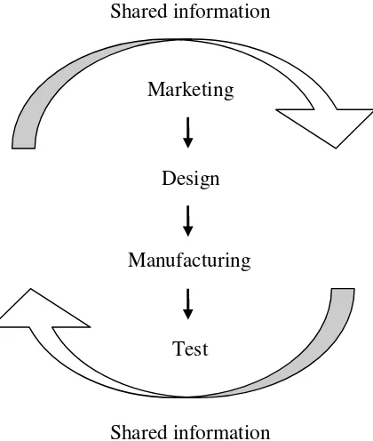
CE approach:
Figure 2.3: CE approach.
2.4 Importance and Benefits of Concurrent Engineering
Importance of CE:
a. Minimize product life cycle.
b. Decrease development and manufacturing costs. c. Maximize product quality.
d. Teamwork.
Shared information
Shared information Marketing
Test Design