UNIVERSITI TEKNIKAL MALAYSIA MELAKA
INVESTIGATION OF NOZZLE HEIGHT OF ABRASIVE
WATER JET MACHINING ON MILD STEEL GEAR SURFACE
CUTTING PARALLELISM
This report submitted in accordance with requirement of the Universiti Teknikal Malaysia Melaka (UTeM) for the Bachelor Degree of Engineering Technology
(Process and Technology) (Hons.)
by
MUHAMMAD NIZAM BIN ABD SAMAT B071210462
900502-01-5063
UNIVERSITI TEKNIKAL MALAYSIA MELAKA
BORANG PENGESAHAN STATUS LAPORAN PROJEK SARJANA MUDA
TAJUK: Investigation Of Nozzle Height Of Abrasive Water Jet Machining On
Mild Steel Gear Surface Cutting Parallelism
SESI PENGAJIAN: 2015/16 Semester 2
Saya MUHAMMAD NIZAM BIN ABD SAMAT
mengaku membenarkan Laporan PSM ini disimpan di Perpustakaan Universiti Teknikal Malaysia Melaka (UTeM) dengan syarat-syarat kegunaan seperti berikut:
1. Laporan PSM adalah hak milik Universiti Teknikal Malaysia Melaka dan penulis. 2. Perpustakaan Universiti Teknikal Malaysia Melaka dibenarkan membuat salinan
untuk tujuan pengajian sahaja dengan izin penulis.
3. Perpustakaan dibenarkan membuat salinan laporan PSM ini sebagai bahan pertukaran antara institusi pengajian tinggi. atau kepentingan Malaysia sebagaimana yang termaktub dalam AKTA RAHSIA RASMI 1972)
(Mengandungi maklumat TERHAD yang telah ditentukan oleh organisasi/badan di mana penyelidikan dijalankan)
________________________________
Alamat Tetap:
No 39 Jalan Mawar 4, Taman Tangkak
Jaya 2, 84900 Tangkak,
Johor.
Disahkan oleh:
____________________________
Cop Rasmi:
DECLARATION
I hereby, declared this report entitled ―Investigation Of Nozzle Height Of Abrasive Water Jet Machining On Mild Steel Gear Surface Cutting Parallelism‖ is the results
of my own research except as cited in references.
Signature :………
Name : MUHAMMAD NIZAM BIN ABD SAMAT
v
APPROVAL
This report is submitted to the Faculty of Engineering Technology of UTeM as a partial fulfillment of the requirements for the degree of Bachelor of Engineering Technology (Process and Technology) (Hons.). The member of the supervisory is as follow:
vi
ABSTRACT
vii
ABSTRAK
viii
DEDICATIONS
ix
ACKNOWLEDGMENTS
Bismillahirrahmanirrahim.
In the name of Allah, the Almighty, who guide us to the truth, the knowledge and with regards to Prophet Muhammad S.A.W for guiding us to the light. I thank to Allah for giving me the chance to finish the writing of this report.
I would like to take this opportunity to express my appreciation to my supervisor, Mr. Engr Hanizam Bin Hashim and co-supervisor Mr. Mohd Kamal Bin Musa for his kindness, advice and guidance to help me accomplish this project from day one and beyond. I cannot pay back for all his contributions were definitely helped me a lot in this project.
I would also like to thank all partners for their significant advice and help. And also for my beloved one, who always supported me throughout this project and for helping me get through it. Just calm can repay all the kindness you all. Furthermore, I also thank my parents Abd. Samat Bin Ithnin and Kamisah Binti Haji Md Dis which helped a lot in terms of finance, advice and encouragement.
Finally, I would like to thank to any other individual or group that I no longer had also played an important role in doing my final year project and report.
x
TABLE OF CONTENTS
DECLARATION ... iv
APPROVAL ... v
ABSTRACT ... vi
ABSTRAK ... vii
DEDICATIONS ... viii
ACKNOWLEDGMENTS ... ix
TABLE OF CONTENTS ... x
LIST OF FIGURES ... xiv
LIST OF TABLE ... xv
LIST OF SYMBOLS AND ABBREVIATIONS ... xvi
CHAPTER 1 ... 1
1.0 Introduction ... 1
1.1 Project Background ... 3
1.2 Problem Statement ... 4
1.3 Objective ... 4
1.4 Work Scope ... 5
CHAPTER 2 ... 6
2.0 Introduction ... 6
2.1 Abrasive Waterjet Machining ... 6
xi
2.4 Gear Fabrication ... 11
2.4.1 Method of Gear Manufacturing ... 12
2.5 Mild steel ... 13
2.6 Cutting Parameter of Abrasive Waterjet Machining ... 14
2.6.1 The Effect of Water Pressure ... 15
2.6.2 The effect of water pressure ... 15
2.7 Cutting Parameter of Abrasive Waterjet Machining ... 16
2.7.1 Kerf taper ... 16
2.7.2 Kerf characteristics... 18
2.7.3 Cutting Kerf ... 21
2.7.4 Condition Edge on cutting Kerf ... 23
2.8 Statistical Analysis ... 24
2.9 Main Effect Plot ... 24
CHAPTER 3 ... 26
3.0 Introduction ... 26
3.1 Project Planning ... 26
3.2 Material Equipment ... 28
3.2.1 Water Jet Machining ... 28
3.2.2 Profile Projector ... 30
3.2.3 Inverted Research Microscope ... 31
3.3 Material Selection ... 33
xii
3.3.2 Mild Steel ... 34
3.4 Experiment Setup ... 34
3.4.1 Mild Steel Workpiece Preparation ... 35
3.4.2 Clamping Position ... 36
4.1 The Effect of Angle Taper Ratio using Different Nozzle Height ... 43
4.1.1 Comparison of Angle Taper Ratio using Different Nozzle Height... 43
4.2 Statistical Analysis of Angle Cutting Taper using Main Effect Plot Minitab Software ... 47
4.3 Cutting Edge Condition at Different Taper Ratio ... 48
xiv
LIST OF FIGURES
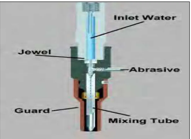
Figure 2.1 : A schematic diagram of an abrasive water jet. ... 8
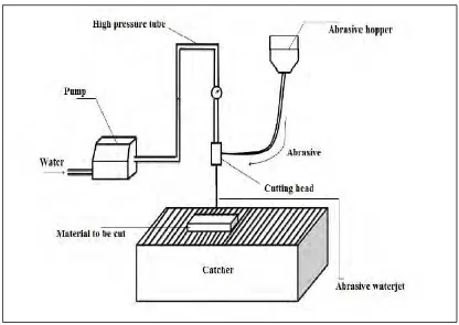
Figure 2.2 : Schematic of AWJ machining system ... 9
Figure 2.3 : Abrasive Grain 80 Mesh ... 11
Figure 2.4 : Gear cut using AWJM ... 12
Figure 2.5 : Schematic of a through-cut kerf ... 19
Figure 2.6 : Schematic of a non-through cut kerf ... 19
Figure 2.7 : Characteristics of the Taper of the Cutting Gap ... 20
Figure 2.8 : Cutting kerf ... 21
Figure 2.9 : Typical Cutting kerf on mild steel ... 22
Figure 2.10 : Schematically Condition Edge on Cutting Kerf of waterjet. ... 23
Figure 2.11 : Statistical analysis main effect plot. ... 25
Figure 3.1 : Research development flow... 27
Figure 3.2 : Water Jet Machine Type Mach 2 1313b ... 29
Figure 3.3 : Profile Projector ... 31
Figure 3.4 : Inverted Research Microscope ... 31
Figure 3.5 : Mild steel workpiece ... 33
Figure 3.6 : Workpiece dimension for AWJM cutting experiment ... 35
Figure 3.7 : Clamping positon for AWJM cutting process ... 36
Figure 3.8 : Sample of data Main Effect Plot in Minitab 17 ... 40
Figure 3.9 : Sample of graph Main Effect Plot in Minitab 17 ... 41
Figure 3.10 : Characteristics of the Taper of the Cutting Gap ... 42
Figure 4.1 : Line graph relationship between nozzle height againt angle taper ratio 46 Figure 4.2 : Main effects plot for angle taper ratio means ... 47
xv
Table 2.1 : Major AWJM Process Parameters ... 14
Table 3.1 : Specification of Mach 2 WJM ... 28
Table 3.2: Specification of Profile Projector... 30
Table 3.3: Specification of Inverted Research Microscope ... 32
Table 3.4 : Physical properties of mild steel as work piece ... 33
Table 3.5 : Specification of Abrasive ... 34
Table 3.6: Procedure of AWJM using Flow Mach2 1313b ... 37
Table 3.7: Procedure of Profile Projector ... 38
Table 3.8: Angle taper ratio ... 39
Table 4.1 : Angle taper ratio for material thickness 10mm... 44
Table 4.2 : Angle taper ratio for material thickness 20mm... 45
xvi
LIST OF SYMBOLS AND ABBREVIATIONS
AWJM = Abrasive Waterjet Machining HAZ = Heat Affected Zone
CNC = Computer Numerical Control NC = Numerical Comtrol
1
CHAPTER 1
INTRODUCTION
1.0 Introduction
2
especially suitable for very soft, brittle and fibrous materials. This technology is less sensitive to material properties as it does not cause chatter. This process is without much heat generation, so machined surface is free from heat affected zone and residual stresses. AWJM has high machining versatility and high flexibility. The major drawback of this process is, it generate loud noise and a messy working environment (P. K. Mishra, 2005).
This technology is most widely used compared to other non-conventional technology because of its distinct advantages. It is used for cutting a wide variety of materials ranging from soft to hard materials. This technique is especially suitable for very soft, brittle and fibrous materials. This technology is less sensitive to material properties as it does not cause chatter. This process is without much heat generation, so machined surface is free from heat affected zone and residual stresses. AWJM has high machining versatility and high flexibility. The major drawback of this process is, it generate loud noise and a messy working environment (P. K. Mishra, 2005).
Gears have existed since the invention of rotating machinery. Gear is a tooth wheel mechanical device used to transmit power and motion between machine parts. Gears are used in many applications, such as automobile engines, household appliances, and computer printers. Gear provides long life cycles and can transmit power at to 98 percent efficiency. Gear manufacturing refers to the making of gears. Gears can be manufactured by a variety of processes, including casting, forging, extrusion, powder metallurgy, and blanking. As a general rule, however, machining is applied to achieve the final dimensions, shape and surface finish in the gear. A gear also can be described as a toothed wheel that when meshed with another smaller in diameter toothed wheel (the pinion) will transmit rotation from one shaft to another. The primary function of a gear is to transfer power from one shaft to another while maintaining a definite ratio between the velocities of the shaft rotations. The teeth of a driving gear mesh push on the driven gear teeth, exerting a force component perpendicular to the gear radius. Thus, a torque is transmitted, and because the gear is rotating, power is transferred (Prof. K. Gopinath & Prof. M.M.Mayuram, 2007).
3
low carbon components of ingot iron. Mild steel also known as plain-carbon steel, is now the most common form of steel because its price is relatively low while it provides material properties that are acceptable for many applications. Low carbon steel contains approximately 0.05–0.15% carbon making it malleable and ductile. Mild steel has a relatively low tensile strength, but it is cheap and easy to form. Mild steels suffer from yield-point run out where the material has two yield points. The first yield point (or upper yield point) is higher than the second and the yield drops dramatically after the upper yield point. If low carbon steel is only stressed to some point between the upper and lower yield point. Low-carbon steels contain less carbon than other steels and are easier to cold-form, making them easier to handle (totalmateria.com, 2001)
1.1 Project Background
Abrasive Water Jet Machining (AWJM) cutting has been widely used in various industries for cutting such as reinforced concretes, cutting metal structure, cutting food as well for cleaning and coating removal. However, the application of AWJM technique has found mostly in metal manufacturing, automotive, glass and aerospace industries. Ceramics, marble composite layer, titanium sheet as well as pattern cutting of various materials uses an AWJM technique because those are difficult to cut material.
4
1.2 Problem Statement
Accuracy of the water jet cutting is mainly defined by the form of the cutting gap. Form of cutting gap is one of the main problems having an effect on the accuracy of abrasive water jet cutting. The form of the kerf has been always complex, cut surfaces are almost never parallel. In most cases the kerf is wider at the upper side than the lower side, where the jet goes out from the work piece. For gears fabrication, the process required accurate cutting process, especially for fitting purposes. Therefore, the taper issue on cutting surface should be avoided. One of the common cutting processes of such product is using an abrasive water jet cutting. In this research, the best cutting parameters, such as nozzle height, pressure, and abrasive are being focused on.
The aim of the research work was to get connections between the technological parameters and the taper of the kerf in order to find cutting parameters which can get parallel cut surface.
1.3 Objective
In order to complete the Final Year Project, there are some objectives that must be accomplished. The objectives are:
i. To investigate the cutting taper on the mild steel work piece using Abrasive Water Jet machining.
ii. To select the best height of the nozzle during cutting process of cutting parallelism.
5
6
CHAPTER 2
LITERATURE REVIEW
2.0 Introduction
Literature review discussed the relevant topics and a guide for studies. This section will give part in order to get more information about Abrasive Water Jet Machining (AWJM) and will give an idea how to operate the machine. At an early stage of the studies, some gap analysis has been carried out in order to ensure the relevance of this research. Reference books, research journals and online conference article were the main source in the thesis guides. This section will include the principle of AWJM, machining properties and cutting taper at the cutting area. History of the AWJM will be story little bit in this section.
2.1 Abrasive Waterjet Machining
Abrasive Water Jet Machining has been one most recently developed non-traditional cutting processes. It was first introduced as a commercial system in 1983 for the cutting glass. Because of its various distinct advantages over the other cutting technologies, such as no thermal distortion on the work piece, high machining versatility to cut virtually any materials, high flexibility to cut any direction, and small cutting process, it is being widely used machining difficult-to-machine material like ceramic, composites and titanium alloy where conventional machining is often not technically or economically feasible, as well as for pattern cutting on various materials (J. Wang, 2003)
7
first commercial system with abrasive entrainment in the jet became available. The added abrasives increased the range of materials, which can be cut with a Watergate drastically (R. V. Shah,2011)
This technology is most widely used compared to other non-conventional technology because of its distinct advantages. It is used for cutting a wide variety of materials ranging from soft to hard materials. This technique is especially suitable for very soft, brittle and fibrous materials. This technology is less sensitive to material properties as it does not cause chatter. This process is without much heat generation, so machined surface is free from heat affected zone and residual stresses. AWJM has high machining versatility and high flexibility. The major drawback of this process is, it generate loud noise and a messy working environment (P. K. Mishra, 2005)
In AWJ machining process, the workpiece material is removed by the action of a high-velocity jet of water mixed with abrasive particles based on the principle of erosion of the material upon which the water jet hits. Comparing with other complementary machining processes, no heat affected zone (HAZ) on the workpiece is produced . High speed and multidirectional cutting capability, high cutting efficiency, ability to cut complicated shapes of even non flat surfaces very effectively at close tolerances, minimal heat build up, low deformation stresses within the machined part, easy accomplishment of changeover of cutting patterns under computer control, etc. are a few of the advantages offered by this process which make it ideal for automation. AWJM is widely used in the processing of materials such as titanium, steel, brass, aluminium, stone, Inconel and any kind of glass and composites . Being a modern manufacturing process, abrasive waterjet machining is yet to undergo sufficient superiority so that its fullest potential can be obtained (M. Korat,2014)
8
Figure 2.1 : A schematic diagram of an abrasive water jet.
Source: International Journal of Advances in Engineering & Technology,2011.
9
Figure 2.2 : Schematic of AWJ machining system Source: Water cutting machine,2008. <http://waterjet-cutting.blogspot.com>
2.2 Working Principle of Abrasive Waterjet Machining
The water jet machining is also known as hydrodynamic machining. The water acts as a saw and cuts a narrow groove in the material. High water pressures range from 60ksi to 200ksi is required to cut from soft to hard materials.
The basic methodology of the process: water is pump at a sufficiently high pressure, 200-400Mpa (2000-4000 bar) using intensifier technology. An intensifier works on the sample principle of the pressure amplification using hydraulic cylinders of the different cross sections. When the water at such pressure is issued through a suitable orifice (generally of 0.2-0.4 mm diameter), the potential energy is converted into kinetic energy, yielding a high velocity jet (1000 m/s). Such high velocity water jet can machine thin sheets/foils of aluminium, leather, textile, frozen food, etc. In pure WJM, commercially pure water (tap water) is used for machining purpose.