UNIVERSITI TEKNIKAL MALAYSIA MELAKA
An Analysis of Jig Designs to Assembly Time in
Plug Assembly Line Using Design of Experiment
Report submitted in accordance with the requirements of the Universiti Teknikal Malaysia Melaka for the
Bachelor’s Degree of Manufacturing Engineering (Manufacturing Management)
By
Shee Chee Shen
Faculty of Manufacturing Engineering
*Laporan dimaksudkan sebagai tesis bagi Ijazah Doktor Falsafah dan Sarjana secara penyelidikan, atau disertasi bagi pengajian secara kerja kursus dan penyelidikan, atau Laporan Projek Sarjana Muda (PSM). ** Jika laporan ini SULIT atau TERHAD, sila lampirkan surat daripada pihak berkuasa/organisasi
berkenaan dengan menyatakan sekali sebab dan tempoh laporan ini perlu dikelaskan sebagai SULIT atau TERHAD.
UTeM Library (Pind.1/2008)
UNIVERSITI TEKNIKAL MALAYSIA MELAKA
BORANG PENGESAHAN STATUS REPORT*
JUDUL: AN ANALYSIS OF JIG DESIGNS TO ASSEMBLY TIME IN PLUG ASSEMBLY LINE USING DESIGN OF EXPERIMENT
SESI PENGAJIAN: 2/2007-2008
Saya SHEE CHEE SHEN
mengaku membenarkan laporan (PSM/Sarjana/Doktor Falsafah) ini disimpan di Perpustakaan Universiti Teknikal Malaysia Melaka (UTeM) dengan syarat-syarat kegunaan seperti berikut:
1. Laporan adalah hak milik Universiti Teknikal Malaysia Melaka .
2. Perpustakaan Universiti Teknikal Malaysia Melaka dibenarkan membuat salinan untuk tujuan pengajian sahaja.
3. Perpustakaan dibenarkan membuat salinan laporan ini sebagai bahan pertukaran antara institusi pengajian tinggi. atau kepentingan Malaysia yang termaktub di dalam AKTA RAHSIA RASMI 1972)
(Mengandungi maklumat TERHAD yang telah ditentukan oleh organisasi/badan di mana penyelidikan dijalankan)
(TANDATANGAN PENULIS)
Alamat Tetap:
APPROVAL
This report submitted to the senate of UTeM and has been accepted as fulfillment of the requirement for the Degree of Bachelor of Manufacturing Engineering (Honors)
(Management). The member of supervisory committee is as follows:
………..
Main Supervisor Prof Madya Dr Adi Saptari
DECLARATION
I hereby, declare this report entitled “An Analysis of Jig Designs to Assembly Time in Plug Assembly Line Using Design of Experiment” is the result of my own research
except as cited in the references.
Signature : ………
i
ABSTRACT
ii
ABSTRAK
iii
DEDICATION
iv
ACKNOWLEDGEMENTS
I would like to extend my warmest gratitude and thankful to my supervisor, Professor Madya Dr. Adi Saptari for his excellent supervision, invaluable guidance, trust, advice and constant help, support, encouragement, and assistance towards me throughout this project.
I would like to express my deepest appreciation to manufacturing Engineering laboratory of Uniersiti Teknikal Malaysia Melaka for providing me the place, time and always show their sincere kindness in helping and gave me useful information especially in contributing and sharing ideas toward this project.
v
List of Abbreviations, Symbols, Specialized Nomenclature………...……… xi
1 INTRODUCTION………..……….……..1
2.2 Different Between Jig and Fixture………....6
2.3 Purpose and Advantage of Jig………...…8
2.4 Basic Requirement and Features of Jig………...9
2.5 Application and Classification of Jig………..…10
2.6 Jig Design Fundamentals………....11
2.7 Design of Experiments (DOE)……….……….…..12
2.8 Various Statistic Analysis Tools……….14
2.8.1 Descriptive Statistics………..14
2.8.2 T-test………..…15
2.8.3 Analysis of Variance (ANOVA)……….………..….16
vi
2.8.5 Stock Chart……….……17
2.8.6 Main Effect Plot……….………..…..18
2.8.7 Interaction Plot………...……19
2.8.8 Boxplot……….………..……20
2.9 Current Research on Analysis of Jig Design………..……20
3 METHODOLOGY………..…….24
4.4 Effect of Different Factor to Assembly Time……….………35
4.4.1 Subject 1………..………..35
4.4.2 Subject 2……….………..……….38
4.5 Most Productive Jig………..………..41
5 DISCUSSION………..43
5.1 Introduction……….43
vii
5.2.1 Jig Design Planning Analysis………...……….………43
5.2.2 Jig Layout and Jig Elemental Design……….…45
5.2.3 Tool Body Design and Produce the Jig……….…….46
5.3 Effect of Different Factor of Jig Design to Response Time………...46
5.3.1 Subject/Operator………..………..47
5.3.7 Factors that Contribute More Significant than Other………..…..55
5.3.7.1 Subject 1……….…...….56
viii
LIST OF TABLES
2.1 Differentiate between jig and fixture 7
2.2 Classification of machining jig 11
2.3 Classification of manual work jig 11
2.4 Example of descriptive statistics of result table 14
2.5 Example of ANOVA: Single factor 16
2.6 The researched have been carried out relating 21
3.1 Design of jig produced 27
3.2 Design of experiment for different jig design 28
4.1 Design of Experiment for factor number, orientation and screwing
process 34
4.2 Descriptive statistics of results subject 1 36
4.3 Average assembly time of subject 1 for each different factor 37
4.4 Descriptive statistics of results subject 2 39
4.5 Average assembly time for each different factor 40
5.1 t-test: paired two sample means between two subjects 47
5.2 ANOVA-Single Factor between two subjects 48
5.3 ANOVA-Single Factor to number plugs per jig (3 or 4) for subject 1 50 5.4 ANOVA-Single Factor to number plugs per jig (3 or 4) for subject 2 50 5.5 ANOVA-Single Factor for orientation for subject 1 51 5.6 ANOVA-Single Factor for orientation for subject 2 52 5.7 ANOVA-Single Factor of screwing process for subject 1 53 5.8 ANOVA-Single Factor of screwing process for subject 2 53 5.9 ANOVA-Single factor combination of number--orientation-screwing for
subject 1 54
5.10 ANOVA-Single factor combination of number--orientation-screwing for
ix
5.11 3 ways ANOVA- Subject 1 for each factors 56
x
LIST OF FIGURES
2.1 Example of double vertical bar chart 17
2.2 Example of stock chart 18
2.3 Example of main effect plot 18
2.4 Example of interaction plot 19
2.5 Example of boxplot 20
3.1 Flow chart of study research planning 25
3.2 Various aspects of jig design procedure 26
4.1 Designs of jig used for the experiments 33
4.2 Main effect plot to the assembly time for subject 1 37
4.3 Main effect plot to assembly time for subject 2 40
4.4 Mean of subject 1 for different set of factors 41
4.5 Mean of subject 2 for different set of factors 42
5.1 Product (Plug) dimension analysis, top view and isometric view 44 5.2 Location for central point of neutral pin, live pin, earth pin and screw 45 5.3 Mean for two subjects with different set of factors 47 5.4 Standard deviation for two subjects with different set of factors 49
5.5 Interaction plot for subject 1 57
5.6 Normal probability plot of standardized effects for subject 1 58 5.7 Pareto chart of standardized effects for subject 1 58
5.8 Interaction plot for subject 2 60
xi
LIST OF ABBREVIATIONS, SYMBOLS, SPECIALIZED
NOMENCLATURE
ANOVA - Analysis of Variance
BS - British Standard
df - Degree of Freedom
DOE - Design of Experiment
MS - Mean Square
PSM - Projek Sarjana Muda p-value - Probability Value
sec - Second
SS - Sum of Square
1
CHAPTER 1
INTRODUCTION
1.1 Background
Today, engineers have become highly interested in the application of anthropometric and biomechanical information, especially to the design of equipment and the arrangement of workstations.
Productivity in assembly line determined by many variables, which included skill of the workers, design of equipment or tools, design of workstation and design of assembly process. Improve one variable among them can brought to the whole productivity improvement.
Workstation design is one of the major areas in which human factor professional can help improve the fit between human, machine and environment. Nowadays, in the industry, assembly job environment workplace design playing a important role that able influencing worker performance, such as use of jig and fixture, position of standing or sitting and working table height. This all aim to design a system or workstation that can reduce human error, increase productivity, and enhance safety and comfort.
2
jig may hinder the process of worker doing their jobs, which the jig is not productive. Design of jig is help worker in performing their job more productive but not hinders the performance.
In this experiment, practical experience is exposed in recording assembly response time data for design of an electrical plug assembly workplace. 2 students are required to assemble 36 plugs for each jig design setting with each assembly time being recorded. This research is investigating the different design of plug assembly jig by design of experiment (DOE). Some different number plug per jig, orientation design and screwing process is analyzed whether contribute to different productivity.
The task given in this research experiment is to analyze the productivity between the different designs of plug jig. The data collected is analyzed using basic statistical method such as t-test, analysis of variance (ANOVA), descriptive statistics, bar chart, stock diagram, interaction plot and main effect plot in order to determine the most contribute factor to assembly time and most productive jig design which is suitable the electrical plug assembly line.
This research project is conducted in Manufacturing Engineering Laboratory of University Teknikal Malaysia Melaka (UTeM).
1.2 Problem Statement
3
The effect of the number plug per jig are investigated, how many is the optimum plugs that give the optimum assembly response time. On this research, design of jig was made to able handle 3 or 4 plugs at the same time. Besides that, the performance given by different orientation of the jig (horizontal or vertical) and design of screwing process (flip the jig and tighten the screw of plug, or took out plug one by one and screw the plug without flip)also analyzed.
A proper jig design used in assembly line is designed to help workers in performing their job easily in plug assembly job and contributes to reduce the assembly response time, but improper or bad design of jig may hinder their performance.
1.3 Objective of Study
The objective of this research is to investigate the different design of plug assembly jig by design of experiment (DOE) to see their contribution to the productivity.
The objectives of this study are:
a) To design different type of plug assembly jig according different number of plug per jig, orientation and screwing process.
b) To investigate the effect of different factor (number plug per jig, orientation of jig, and screwing process) to the response time.
c) To test and verify which plug assembly jig is the most productive.
1.4 Scope of Study
4
This research project is conducted in Manufacturing Engineering Laboratory of University Teknikal Malaysia Melaka (UTeM). Different design of jig are designed and made by researcher. Data gathered - assembly response time is based on the electrical appliance, which is a BS 1363 plug, which assists by different design of jig. The subjects in this research are UTeM students. Subjects are trained to assemble plug for total 2 hours until they are comfortable and familiar in doing the plug assembly job. So the data collected are consider that the assembly response time are constant, which the subject has doing assembly job in a constant performance. Height of table is set to 91 cm for light work and precision work. The position of sitting selected while performing the plug assembly task.
5
CHAPTER 2
LITERATURE REVIEW
2.1 Introduction
Many manufacture tasks require precise alignment during assembly or during other operations such as plain holding, bending, cutting, drilling, or gluing. Normally, when doing an assembly task, a reliable assembly tooling needed to able to hold components in an accurate and repeatable position, prevent undesired motion of components, and avoid posing interference problems.
Especially for repeated assembly line processes, one or more flexible or specific work holding devices can use for great aids and time savers. Some commercial ones are available and many can be made from ply wood, metal or plastic material. Often many tool accessories can be adapted for use, but normally all facilitate their associated own processes.
There are many standard work holding devices such as jaw chucks, machine vises, and drill chucks, which are widely used in workshops and are usually kept in stock for general applications.
6
The use of a jig or fixture makes a fairly simple operation out of one which would otherwise require a lot of skill and time. Both jig and fixture position components accurately and hold components rigid, prevent movement during working in order to impart greater productivity and part accuracy to perform on the work piece a manufacturing operation. (Andrew, Y. C. N., et al., 2004)
A jig is a type of fixture with means for positively guiding and supporting tools for assembly and related operations. (Henriksen, E. K., 1973)
Jig and fixture are production tools used to accurately manufacture duplicate and interchangeable parts. Jig and fixture are specially designed so that large numbers of components can be machined or assembled identically, and to ensure interchangeability of components.
Jig and fixture may be large (as in air plane fuselages are built on picture frame fixtures) or very small (as in watch making). Their use is limited only by job requirements and the imagination of the designer.
Jig and fixture must be clean, undamaged and free from grit, which components must not be forced into a jig or fixture. Jig and fixture are precision tools and some of them are expensive to produce because they are made to fine limits from materials with good resistance to wear. They must be properly stored or isolated to prevent accidental damage, and they must be numbered for identification for future use.
2.2 Different Between Jig and Fixture
7
that hold and move a work piece in relation to a tool. Often they are designed as
carriages that slide.
Fixture is often clamped on the machine table. A fixture is static devices that hold the
work piece or tools in stationary and correct position in relation to machine tools
during the operation. There is something a provision for setting that tool with respect to work piece or fixture but the tool is not guided as in jig. The features are employed for holding work in milling, grinding, planning or turning operation. Some of the more typical examples of fixtures are fences, such as a ripping fence on the
table saw. Jig is generally used for more temporary holding and positioning, while
fixture considered more permanent and complex.
From the construction point of view jig are lighter in weight if compare to fixture. They are quicker handling and clamping with that the table. They are used for particularly drilling, taping operations. Fixture is generally heavier in construction and is bolted rigidly on the machine table.
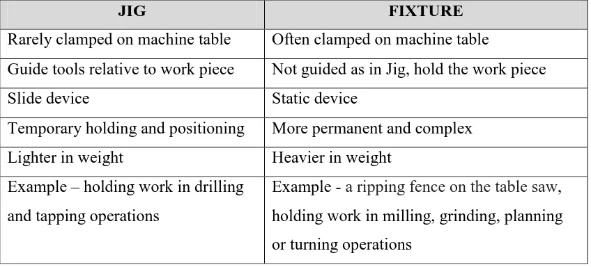
Table 2.1: Differentiate between jig and fixture
JIG FIXTURE
Rarely clamped on machine table Often clamped on machine table
Guide tools relative to work piece Not guided as in Jig, hold the work piece
Slide device Static device
Temporary holding and positioning More permanent and complex
Lighter in weight Heavier in weight
Example – holding work in drilling and tapping operations
8 2.3 Purpose and Advantage of Jig
The main purpose of jig is to locate work quickly and accurately, support it properly, and hold it securely, thereby ensuring that all parts produced in the same jig will come out alike within specified limits. In this way accuracy and interchangeability of the parts are provided.
It also reduces working time in the various phases of the operation, in the setup and clamping the required dimensions, and during the cutting operation itself by allowing heavier feeds due to more efficient work support hence improving production rate.
The use of jig eliminates individual marking positioning and frequent checking before machining operation starts, thereby resulting in considerable saving in set-up time. In addition, the usage of work holding devices saves operator labor through simplifying locating and clamping tasks and makes possible the replacement of skilled workforce with semi-skilled labor, hence effecting substantial saving in labor cost which also translates into enhanced production rate.
Jig expand the capacity of standard machine tools to perform special operations, which they make it possible to use plain or simplified, and therefore less expensive, machinery instead of costly standard machines. In the other words, they turn plain and simple machine tools into high production equipment and convert standard machines into the equivalent of specialized equipment.
By maintaining or improving the interchangeability of the parts, a jig contributes to a considerable reduction in the cost of assembly. In effect, jig reduces costs and improves the potential of standard machines and the quality of the part produced.
9
to design jig in such way as to make it foolproof and thereby contribute to added safety for the operator as well as for the work.
2.4 Basic Requirement and Features of Jig
A good jig must satisfy the following conditions: a) Reduction of response time
The design of jig should be such that the process of loading and unloading the components takes the minimum possible time and enables on easy loading and clamping should be such that ideal time is reduced to minimum.
b) Convenience to use
The locating and supporting surfaces should be replaceable that is not permanently fastened so that of worn out they may be replaced by new ones. Moreover they should be standardized so that their interchangeable manufacture is possible.
c) Not cause damage to work piece
Designed jig should not damaged component of the work pieces. Due to this situation, sometime natural material needed for jig. For this study, ply wood selected as plug assembly jig, because harden material will damaged pin of the plug.
d) Economic soundness