PJP/2010/FKEKK (29D) S769
RECONFIGURABLE BEAMFORMING NETWORK BY USING PASSIVE PHASE SHIFTER
AZAHARI BIN SALLEH ABD SHUKUR BIN JA’FAR
MOHAMAD ZOINOL ABIDIN BIN ABD. AZIZ ZULKIFLI BIN SHARIFF
RESEARCH VOTE NO: PJP/2010/FKEKK (29D) S769
FAKULTI KEJURUTERAAN ELEKTRONIK DAN KEJURUTERAAN KOMPUTER UNIVERSITI TEKNIKAL MALAYSIA MELAKA
i
“I hereby declare that this report is the result of my own work except for quotes as cited in the references.”
ii
ACKNOWLEDGEMENT
First and foremost, I would like to thank Allah for His blessing. He gave me physical and mental strength to carry this research up to completion. I take this opportunity to express my profoundest gratitude and deepest regards to all those who gave me the possibility to successfully complete this research. I wish to express a million thanks to CRIM and FKEKK for the financial support, exemplary guidance, monitoring and constant encouragement throughout the development of the research.
iii RECONFIGURABLE BEAMFORMING NETWORK BY USING PASSIVE
PHASE SHIFTER
(Keywords:Beamforming, Phase Shifter, Butler Matrix, CST)
This research presented the design of reconfigurable beamforming using phase shifter at input port which operated at Industrial, Scientific and Medical (ISM) frequency (2.4 GHz). Recently, the growing technology of communication systems is rapidly increasing the use of mobile and computer. This will be increasing the demand of data and capacity system. The smart antenna used to rejecting the interference signal, improve the signal to noise ratio (SNR) and increasing the channel capacity of the system. The beam forming network (BFN) is a network that controls the phases and amplitudes of the excitation current for smart antennas. The switched beam system produces the fixed multiple narrow beams and select from them the suitable beam that gives the strongest signal level. The problem is to ensure the mobile in the dynamic range, the system will shift beam one by one until meet the mobile. In this project, phase shifter used to reconfigurable phase of Beamforming network. Result simulation is obtained by using computer simulation technology (CST) in term of S-parameter in magnitude and phase and phase differences between ports. The 4×4 Butler Matrix, was fabricated on Flame Retardant Board type 4 (FR4 board). The beam position was calculated by using result progressive phase shift. Lastly, the simulation and measurement result was compared. The new beam positions are 1R, 2R, 2L, 1L if compare to conventional beam positions are 2R, 1R, 1L, 2L. As a conclusion, the project successful obtained the new beam position of 4×4 Butler Matrix.
Key Researchers: Azahari Bin Salleh Abd Shukur Bin Ja’far
Mohamad Zoinol Abidin Bin Abd. Aziz Zulkifli Bin Shariff
E-mail :[email protected] Tel. No.: 06-5552104
iv
TABLE OF CONTENTS
CHAPTER TITLE PAGE
PROJECT TITLE i
STATUS REPORT ii
DECLARATION iii
ACKNOWLEGDEMENT v
ABSTRACT vi
ABSTRAK vii
TABLE OF CONTENTS viii
LIST OF TABLES xi
LIST OF FIGURES xiii
LIST OF ABBREVIATIONS/ SYMBOLS xvi
LIST OF APPENDICES xviii
I INTRODUCTION
1.1 BACKGROUND OF THE PROJECT 1
1.2 PROBLEM STATEMENT 2
1.3 OBJECTIVE 2
1.4 PROJECT SCOPE 3
1.5 PROJECT METHODOLOGY 3
1.6 REPORT OUTLINE 5
1.7 SUMMARY 5
II LITERATURE REVIEW
2.1 SMART ANTENNA 6
v
2.3 BEAM FORMING NETWORK 12
2.3.1 Blass Matrix 15
2.3.2 Butler Matrix 16
2.4 COMPONENT IN BUTLER MATRIX 17
2.4.1 Hybrid Coupler 18
2.4.2 Crossover Coupler 20
2.4.2 Phase Shifter 22
2.5 SUMMARY 23
III METHODOLOGY
3.1 INTRODUCTION 24
3.2 PROCEDURES TO DESIGN
RECONFIGURABLE BEAMFORMING
24
3.3 DESIGN DEVELOPMENT OF THE BUTLER MATRIX
25
3.3.1 The Design of 90° Hybrid Coupler 26 3.3.1 Crossover coupler 28 3.3.2 Phase Shifter -45° 29 3.3.3 Phase Shifter 0° 32 3.3.4 Combination of Butler Matrix
Components
33
3.3.5 Combination Butler Matrix with Phase Shifter
36
3.4 SIMULATION PROCESS 37
3.3 PROTOTYPE FABRICATION 41
3.3.1 Mask Process 41
3.3.2 Photo Exposure Process 42 3.3.3 Dilution Process 42
3.3.4 Etching Process 42
3.4 MEASUREMENT SETUP 43
vi
IV RESULT ANALYSIS AND DISCUSSION 45
4.1 INTRODUCTION 45
4.2 SIMULATION RESULT OF BUTLER MATRIX 45
4.2.1 Hybrid Coupler 46
4.2.3 Crossover coupler 50 4.2.5 Phase Shifter -45° 54 4.2.7 Phase Shifter 0° 56 4.2.8 Combination of Butler Matrix
Component
59
4.3 IMPLEMENTATION OF ADDITION PHASE SHIFTER ON BUTLER MATRIX
63
4.4 SUMMARY 69
V CONCLUSION AND FUTURE WORK
5.1 CONLCUSION 70
5.2 FUTURE WORK 71
vii LIST OF TABLES
NO TITLE PAGE
2.1 S-Parameter For Conventional 90° Hybrid Coupler
19
2.2 S-Parameter For Conventional 0db Coupler 21 3.1 The Butler Matrix Specification Table 25 3.2 Width And Length Value For Each Impedance
Value In Hybrid Coupler
27
3.3 Width And Length Value For Crossover Coupler 28 3.4 The Value Of Width And Length Dimension 29 3.5 The Dimension Of Phase Shifter 0° 32 3.6 Phase Shifter Design Parameter At Input Port
And Output Port
35
3.7 Layout All Component Of 4×4 Butler 40 4.1 Shown The Phase Different Between Through
Port And Coupled Port.
49
4.2 S-Parameter Of Crossover Coupler 53
4.3 Simulation Result 61
4.4 Measurement Result 61
4.5 Phase Error Of ß Simulation And Measurement 62
4.6 Beam Position 63
4.7 Phase Shifter Parameter At Input Port And Output Port (Configuration 1)
64
4.8 Phase Shifter Parameter At Input Port And Output Port (Configuration 2)
65
4.9 Result for parameter design 1; 0°, 45°, 90°, 135° 65 4.10 Result for parameter design 2; 135°, 0°, 45°, 90°
viii 4.13 Phase Different (Measurement) 66 4.14 Phase Error Of ß Simulation And Measurement 67
ix LIST OF FIGURES
NO TITLE PAGE
1.1 Flow chart of methodology 4
2.1 Analogy of human body system 7
2.2 Coverage 120° 8
2.3 Radiation pattern 9
2.4 Microstrip dimension 10
2.5 EM field 11
2.6 Radiation pattern with array 13 2.7 Flow chart of the types of beam forming 15
2.8 Blass Matrix 16
2.9 The 4 X 4 Butler Matrix 17
2.10 Hybrid Coupler 19
2.11 Layout Of Hybrids 20
2.12 Illustration that represents the function Of 0 dB Crossover
21
2.13 Conventional 0 dB Coupler 22
2.14 Cross-Coupler Or 0 dB Coupler with using 25ohm at middle arm
22
2.15 Straight Phase Shifter 23
3.1 The 4×4 Butler Matrix 26
3.2 Hybrid Coupler 27
3.3 Crossover-Coupler Or 0db Coupler with using 25ohm at middle arm
28
x
3.8 Straight 0° Phase Shifter 32
3.9 Modified Of 0° Phase Shifter 33 3.10 Block Diagram Butler Matrix 33
3.11 Layout Of Butler Matrix 35
3.12 Layout 4×4 Butler Matrix with additional Phase Shifter at input port
37
3.13 Waveguide port for Hybrid Coupler 38 3.14 Boundary conditions for Crossover Coupler 39 3.15 Loft method
3.16 Layouts In Corel Draw 12 Software 41
3.17 Etching process 42
3.18 4×4 Butler Matrix (Fabrication) 43 3.19 Figure Reconfigurable Beamforming (Fabrication) 43 3.20 The Butler Matrix was measured by using spectrum
analyzer network
44
4.1 Simulation layout of Hybrid Coupler 46 4.2 S-Parameter of Hybrid Coupler 47
4.3 Phase different 47
4.4 Surface current in Hybrid Coupler at 180 degree 48 4.5 Layout of miniature Hybrid Coupler 48
4.6 S-Parameter 49
4.7 Conventional Crossover Coupler 50
4.8 S-Parameter 51
4.9 Phase different 52
4.10 Surface current for Crossover 52 4.11 (a) S-Parameter In Magnitude
(b) Phase different
54
4.12 Phase Shifter -45 degree 55
4.13 Phase shift 55
4.14 Surface current at 0 degree 56 4.15 -45 degree Phase Shifter with compact size 56
4.16 Phase shift 57
4.17 The layout design of 0° Phase Shifter
xi 4.19 Shown the phase shift is a 0.0239° 58
4.20 The phase shift design 1 59
4.21 The phase shift design 2 59
4.22 4×4 Butler Matrix 60
4.23 Below Part Of Butler Matrix 61 Above Part Of Butler Matrix 61 4.24 Beam Position For Butler Matrix (a) Theoretical 63
(b) Simulation 63
(c) Measurement 64
4.25 Reconfigurable Beamforming 68
4.26 Return Loss 68
xii LIST OF ABBREVIATIONS/ SYMBOLS
AF - Array Factor
AP - Access Point
BER - Bit Error Rate
EM - Ectromagnetic
FR4 - Flame Retardant Type 4
GHz - Giga Hertz
HPBW - Half-Power Beamwidth
IEEE - Institution of Electrical and Electronic Engineer IF - Intermediate Frequency
ISM - Industrial, Scientific, Medical LAN - Local Area Network
PCB - Printed Circuit Board
RF - Radio Frequency
SDMA - Spatial Division Multiple Access SINR - Signal to Interference and Noise Ratio SIR - Signal to Interference Ratio
SOI - Signal Of Interest SNR - Signal to Noise Ratio TEM - Transverse-Electromagnetic
UV - Ultra Violet
WLAN - Wireless Local Area Network
dB - decibel
1R - First beam on the right side of polar plot 1L - First beam on the left side of polar plot 2R - Second beam on the right side of polar plot 2L - Second beam on the left side of polar plot W - Width of rectangular Microstrip line L - Length of rectangular Microstrip line ɛr - Dielectric constant
xiii
λg - Guided wavelength
N - Number of elements
d - distance between antenna elements
θ - phase
β - phase difference between port elements
k - wave number
xiv LIST OF APPENDICES
NO TITLE PAGE
1
CHAPTER I
INTRODUCTION
1.1 Background of the Project
Recently, the growing technology of communication system is rapidly increased the user of mobile and computer. This will be increase the demand of data and capacity system. To overcome this problem, several studies about the smart antenna have done. The smart antenna used to rejecting the interference signal, improve the signal to noise ratio (SNR) and increasing the channel capacity of the system. Smart antenna will be dividing in two main categories, first, adaptive antenna array and switched beam system. An adaptive antenna array aims to reject automatically interference signals by modifying its radiation pattern using adaptive algorithms. This modification will steering the main lobe in desired signal direction and create the null pattern in interference directions. This will increase the signal to noise ratio.
2
order to track desired with best beam. The second class based on pattern modification that to create same view, by design a new class of micro strip butler matrix, which can be used as feeding network antenna for multiple array antenna.
The butler matrix is easily producing the various beams signal with different directions. But different for adaptive antenna array, that use more intelligent process to detect the desired mobile user and reject the interference mobile. Until now, most studies had done on the simulation process to observe the performance of beam forming network by using butler matrix [1].
1.2 Problem Statement
Recently, the growing technology of communication system is rapidly increased the user of mobile and computer. This will be increase the demand of data and capacity system. The smart antenna used to rejecting the interference signal, improve the signal to noise ratio (SNR) and increasing the channel capacity of the system. The beam forming network (BFN) is a network that controls the phases and amplitudes of the excitation current for smart antennas. Switched beam system produce the fixed multiple narrow beams and select from them the suitable beam that gives the strongest signal level. The problem is to ensure the mobile in the dynamic range, the system will shift beam one by one until meet the mobile. In this project, phase shifter used to reconfigurable phase of Beamforming network
1.3 Objective
3
1.4 Project Scope
The main scope in this research is to design reconfigurable beam forming network by using phase shifter. For design reconfigurable beam forming, the 4×4 butler matrix is commonly chosen, that because butler matrix able to generate multi-beam of input signal for antenna with different angle direction. The all component of4×4 butler matrix and phase shifter will be design separately and was simulated in CST suite software. The all component were analyze with consider their characteristic with refer to S-parameter result. After finish simulation and analyze part, the design will fabricate on FR4 board and the chemical etching will be used to complete the fabricate part.
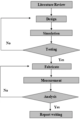
1.5 Project Methodology
To make this research is done at in time; the flow chart is needed to handle this research follow the right steps. The figure 1.1 has shown the flow chart for this research. At first step for beginning this project, literature review activities need to gather information about beam forming and study the design of previous research of beam forming network system. This important to up the basic fundamental about the theories, parameter, design and different method to design beam forming network. The literature study also review about the component in the beam forming network design. The butler matrix and the other method also are review and understand the fundamental of them.
4
Then the phase shifter is designed and will integrate at input port of Butler Matrix. After that, the combination was simulated and the data of parameter are recorded. The fabrication process will be proceeding with printing the design on the transparency and data will be transfer to the FR4 board using UV machine. Then the FR4 will be etching with chemical liquid. For the last stage, the board will solder with connector at input and output port. The design will be measured by using Spectrum Analyzer. All data will be recorded and comparison with the conventional design will be made. The report writing comes out with the measurement and simulation result.
Figure 1.1: flow chart of methodology Yes
No No
Report writing Measurement
Fabricate
Analysis Literature Review
Simulation Design
Testing
5
1.6 Report Outline
This report is organized in fives chapters. Chapter one provides a general idea of the project and the introduction of the project. Chapter two describes theory and characteristic of butler matrix. Chapter three explains the methodology including the calculating and simulation process. Chapter four discusses about the result and analysis project. Lastly, chapter five includes the conclusions and future work to improve this project.
1.7 Summary
6
CHAPTER II
LITERATURE REVIEW
2.1 Smart Antenna
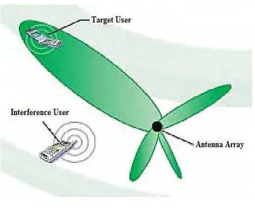
Smart antenna is design with purpose to reduce the co-channel interference fading in mobile system with rejecting the interference signal and increasing the desired signal beam. Those happen because the number of mobile user increasing rapidly. Then, by using the smart antenna technology, the wireless system would be better coverage and capable to increase the signal to noise ratio (SNR) of the system [1].
7
Figure 2.1: analogy of human body system
If have additional speaker interference in the conversation, the listener will tuning the voices at different frequency of voice and classification the second speaker as interference signal and concentrate at first speaker voice as signal. The listener also can give feedback in the conversation with transmit the feedback voice using mouth toward the speaker. The signal processor will measured the signal direction of arrival (DOA) of the signal of interest (SOI) and reproduce the excitation (gain and phase of the signal) to generate the radiation pattern with tuning out the interference signal [4].
8
Gain = 10 log (M) [1]
M = number of beams per sectors
Figure 2.2: coverage 120° [4]
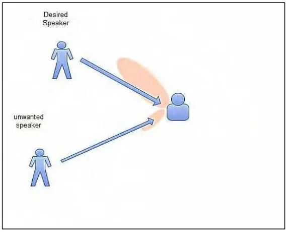
Smart antenna system has two main category; switched beam systems and adaptive antenna array. The switched beam systems are generated multiple narrow beams and selects from them the suitable beam that give the strongest signal level. By selecting one or more signal beam, the power transmit in through port direction can be maximized. The switched beam systems purpose to improve the gain according the location of user, and also used to locate the user of mobile with using the reconfigurable beam forming network. The beam will switch until the user was detected as in figure 2.3(a).
9
Figure 2.3 (a)
[image:24.595.210.464.91.583.2]Figure 2.3 (b)
Figure 2.3: Radiation pattern a) Switched beam antenna, b) Adaptive antenna array [2]
[image:24.595.217.458.91.293.2] [image:24.595.209.467.357.571.2]
![Figure 2.2: coverage 120° [4]](https://thumb-ap.123doks.com/thumbv2/123dok/603955.72114/23.595.222.441.176.355/figure-coverage.webp)