UNIVERSITI TEKNIKAL MALAYSIA MELAKA
DESIGN OF OPERATIONAL COUNTING DEVICE
This report submitted in accordance with requirement of the Universiti Teknikal Malaysia Melaka (UTeM) for the Bachelor Degree of Manufacturing Engineering
(Robotics and Automation) (Hons.)
by
H’NG ZHUANG WEI
B051010203 880925355021
DECLARATION
I hereby, declared this report entitled “Design of Operational Counting Device” is the results of my own research except as cited in references.
Signature : ……….
Author’s Name : ………
APPROVAL
This report is submitted to the Faculty of Manufacturing Engineering of UTeM as a partial fulfillment of the requirements for the degree of Bachelor of Manufacturing Engineering (Robotic and Automation) (Hons.). The members of the supervisory committee are as follow:
………
(TN. HJ. ABDUL RAHIM BIN SAMSUDIN)
………
i
ABSTRAK
Laporan ini membentangkan kajian mengenai alat/peranti untuk mengira bilangan putaran/pusingan sesuatu objek dalam sesebuah sistem. Terrdapat pelbagai kaedah penyelenggaraan seperti penyelenggaraan secara penyaman, sistem pemantauan penyelenggaraan, penjadualan penyelenggaraan, dan ramalan penyelenggaraan telah dilaksanakan dalam industri, namun begitu, masalah sukar untuk menentukan dalam mana-mana tahap ketepatan masih menjadi. Satu contoh seperti kegagalan peranti berputar dan menyebabkan ketangguhan masa yang lama di bahagian pengeluaran. Sebelum melaksanakan kajian sistem kawalan, laporan ini menerangkan reka bentuk
ii
ABSTRACT
This report presents the study on a device for counting the number of rotations of an
iii
DEDICATION
iv
ACKNOWLEDGEMENT
I would grateful and like to thank GOD for I had done this PSM 1 project report successfully. Without the spirit and patience gifted to me, I would not be able to finish up this task.
Firstly, I would like to express my gratitude and special thanks especially to Mr. Sivarao for the guidance in the process to implement and complete my PSM project report. I had learned a lot from him and by his teaching and the information given, had made me stronger to finish up this report. His encouragement, inspiration, patience, support and constant guidance all throughout the semester has helped me to finish up this report. The excellent working relationship between my Co. Supervisor and has provided me with bountiful knowledge and experience for the future. The help rendered to me is priceless, be it from the smallest of its kind to the largest.
I would very much like to thank each and every one of my beloved family members
whose gives support and encouragement to me due to complete my report. Your continuous support will always be my motivations towards success.
v
2.2.1 Vibration analyzer as monitoring system 13
vi
CHAPTER 3: METHODOLOGY 20
3.1 Research Methodology Flow Chart 20
3.2 Process Planning 21
3.4.4 Design the control system 36 3.5 Analysis Method Phase 37 3.5.1 Experiment 1: Accuracies of the inductive sensor detect the
metal on a rotating shaft
38
vii
4.3.1 Experiment 1: Accuracies of the inductive sensor detect the
metal on a rotation shaft
5.2 Recommendation for future work 62
viii
LIST OF TABLES
3.1 3.2 3.3
4.1
Wavecome fastrack supreme GSM modem protocol Characteristics of Short Messaging Service (SMS) Standardized pin out for RS-232 on DB9
Pulley diameter and rotation speed
27 31 36
48 4.2
4.3
Experiment data to choose the best sensor response time Experiment data for the accuracy of the sensor
ix
LIST OF FIGURES
2.1 Programmable maintenance timer system block diagram 9 2.2
2.4 Isometric view of revolution counter tool 12
2.5 General block diagram of a counting device 19
3.1 Research Methodology flow chart 22
3.2 Programmable rotation counter system flow chart 25
3.3 Siemens TC35 GSM 27
3.4 Block diagram of Programmable rotation counter system 28 3.5 Power source for Programmable rotation counter system 29 3.6
Maximum distance detection of the inductive metal sensor to detect metal
Design of body frame
Process flow of parts to complete assembly Body frame
Wheels, bearings, shaft and motors
Design trees that indicates assembly from many parts Simplified design tree consists of only subassemblies Complete assembly of the rig model after mate apply Detail flow chart of counter system
C programming for the sensor response time in CCS C Compiler Graph of detecting RPM against sensor response time
x 4.9
4.10
4.11 4.12
Configuration of GSM modem using Hyper terminal Successfully received notification Hyper Terminal
Coding in CCS C Compiler to allow PIC send SMS Successfully received notification PIC
55 56
xi
LIST OF ABBREVIATIONS, SYMBOLS AND
NOMENCLATURE
SMS - Short Message Service
RPM - Revolution per minute
GSM - Global System for Mobile
PIC - Peripheral Interface Controller
LCD D1
- -
Liquid Crystal Display Diameter 1 of pulley size D2 - Diameter 2 of pulley size
V1 - Rotation speed 1
V2 - Rotation speed 2
1
CHAPTER 1
INTRODUCTION
1.1 Project Background
The maximization, automation, high precision, high efficiency, and
electromechanical integration development tendency of equipment have made enterprise improve production efficiency. However, the enhancement of performance and complexity of equipment and the high correlation between components have led to problems, including frequent paroxysmal failure of machinery, high maintenance expense and long maintenance cycle. A condition monitoring programs offer an innovative mean for modern rotating equipment to implement and schedule predictive maintenance, as opposed to relying on conventional preventive maintenance techniques, vibration, wear and temperature are the three important condition monitoring techniques to predict the health of the rotating machinery.
2
used to count the rotations of an object mobile about an axis, for example, such as a vehicle wheel to track wear of the tire on that wheel.
The development of the programmable rotation counting devices relates generally to
counter circuit and more specifically, it relates to a programmable rotation counting system for generating an output signal at the expiration of a preselected number of operating rotation of industrial equipment. Machinery malfunctioning problems are often sources of increased maintenance costs and disturbances in production activity across the industry. Reliable preventive methodologies are needed to enable cost effective condition based maintenance. This development can be applied in the monitoring of the total amount of operating bearing life cycle in rotating machinery system and generating an output signal after a predetermined number of operating rotation on the rotating machinery system has elapsed.
1.2 Problem Statement
At the operation of various types of bearing in a rotating machinery systems, the number of rotation in which any specific systems are actually running during the
3
1.3 Objective of Project
The objective of this project
(i) To alert user upon meeting the order to perform maintenance action.
(ii) To develop an operational counting system device monitor the mechanical equipment is upon schedule maintenance.
1.4 Scope
This project is focused on a programmable rotation counting system with GSM to provide an alert system to service personnel that the industrial equipment is due for a scheduled maintenance. This is because the difficulty to detect when will the rotating machinery breakdown and causes the production to stop. In addition, we are able to understand the microcontroller. This programmable rotation counting system able to operate at moderate speed at 400-6000 RPM.
1.5 Maintenance Tools
This section presents some of the maintenance tools that directly or indirectly used in engineering.
1.5.1 Revolution counter
A revolution counter known as a device that tracks revolutions of a rotating shaft, disc, or similar rotation object. It is able to return data about the about the speed of rotation as well as simple recording the number of rotations. Some are analog, requiring a mechanical connection with the device they measure, while others may use techniques like laser sighting to collect information. An example of a revolution counter is the tachometer which is commonly use in a vehicle, with a display
4
The revolution counter can return data in the form of revolutions per minute, often with a needle sliding along a graduated scale. The scale may have shaded zones
indicating safe operating speeds. High speed may endanger the equipment and the scale could include green, yellow and red zones or indicating system to alert the
operator to make adjustment on slow down the revolutions per minute to reduce risks of damage or injury.
1.5.2 Maintenance
Maintenance recommendations are based on industry standards and experience in reclamation facilities. However, equipment and situations vary greatly, and sound engineering and management judgment must be exercised when applying these recommendations. Other sources of information must be consulted (e.g.
manufacturer’s recommendations, unusual operating conditions, personal experience
with the equipment, etc.) in conjunction with these maintenance recommendations.
Maintenance activities fall into three categories:
Routine Maintenance - Activities that are conducted while equipment and
systems are in service. These activities are predictable and can be scheduled and budgeted. Generally, these are the activities scheduled on a time-based or meter-based schedule derived from preventive or predictive maintenance strategies. Some examples are visual inspections, cleaning, functional tests, measurement of operating quantities, lubrication, oil tests, and governor maintenance.
Maintenance Testing - Activities that involve using test equipment to assess condition in an offline state. These activities are predictable and can be scheduled and budgeted. They may be scheduled on a time or meter basis but may be planned to coincide with scheduled equipment outages. Since these
activities are predictable, some offices consider them “routine maintenance” or “preventive maintenance.” Some examples are governor alignments and
balanced and unbalanced gate testing.
Diagnostic Testing – Activities that involve using test equipment to assess the
5
repair/replacement or when equipment deterioration is suspected. These activities are not predictable and cannot be scheduled because they are required
after a forced outage. Each office must budget for these events. Some examples are governor troubleshooting, unit balancing, and vibration testing.
1.5.3 Preventive maintenance
Preventive maintenance is meant equipment is maintained before breakdown occurs
or also known as maintenance performed in an attempt to avoid failures, unnecessary production loss and safety violations. This type of maintenance has many different variations and is subject of various researches to determine best and most efficient way to maintain equipment. Recent studies have shown that Preventive maintenance is effective in preventing age related failures of the equipment. For random failure patterns which amount to 80% of the failure patterns, condition monitoring proves to be effective. The effectiveness of a preventive maintenance schedule depends on the reliability centered maintenance (RCM) analysis which it was based on, and the ground rules used for cost-effective.
Some advantages of PM are:
It is predictable, making budgeting, planning, and resource leveling possible. When properly practiced, it generally prevents most major problems, thus
reducing forced outages, “reactive maintenance,” and maintenance costs in general.
It assures managers that equipment is being maintained. It is easily understood and justified.
Preventive Maintenance does have some drawbacks: It is time consuming and resource intensive.
It does not consider the actual equipment condition when scheduling or
6
It can cause problems in equipment in addition to solving them (e.g., damaging
seals, stripping threads).
1.5.4 Condition-Based Maintenance
This maintenance activity relies on knowing the condition of individual pieces of equipment.
Some features of CBM include:
Monitoring equipment parameters such as temperatures, pressures, vibrations,
leakage current, dissolved gas analysis, etc.
Testing on a periodic basis and/or when problems are suspected such as
vibration testing, and infrared scanning. Monitoring carefully operator-gathered data.
Securing results in knowledgeable maintenance decisions which would reduce
overall costs by focusing only on equipment that really needs attention.
1.5.5 Combination of Condition-Based and Preventive Maintenance
A combination of CBM and PM is perhaps the most practical approach. Monitoring, testing, and using historical data and PM schedules may provide the best information on when equipment should be maintained. By keeping accurate records of the “as
found” condition of the equipment when it is torn down for maintenance, one can
7
CHAPTER 2
LITERATURE REVIEW
In this chapter, an overall finding of revolution counter device on rotational machinery, bearing, belting from 1944-2011 are included. Predictive maintenance schedules and preventive maintenance method since 1993-2008 are also presented.
Bearing, belt fault detection and motor failure using neural network based model ranging from year 2004-2011 are included. Vibration protection becomes desirable for rotating machinery when it is operated with certain defects. Thus, to prevent fault on the rotating device by using a vibration analyzer is also covered here from the year 1944 to 2009.
2.1 Revolution Counter
8
MBD sensor with 152 bit memory was able to count 32,487 revolutions without any problem.
Toshio Lino and Hiroshi Nakayama (1999) constructed a full absolute encoder
consists of an absolute angle sensor using the diffused light optical system and magnetic bubble device revolution counter. A high resolution compact angle sensor was realized by using this optical system. Real time data output was also realized by using digital signal processor. By using precision compact magnetic circuits and electrical circuits, the feature of backup battery free revolution counting was brought out. On the other hand, Nino Stojkovic, Zoran Stare and Neven Mijat (2001) portrayed that the measurement of rotational speed can be done in several ways. Three different measurement methods are presented and appropriate resolutions and relative errors are calculated. The method which measures the time between two pulses gives the best results for slow rotation speeds. Meanwhile, the method which counts the number of pulses in time window gives better results for high rotation speeds. Measurement optimization is done by measuring in two modes corresponding to previous methods and relative error is significantly decreased, revolution counter is realized for measuring rotation speeds in range 10-9999 RPM with a sensor which gives one pulse per revolution. A microcontroller is used for switching between the measurement modes as well as for the rotation speed calculation and displaying.
A programmable maintenance timer system was invented and patented by John C.
9
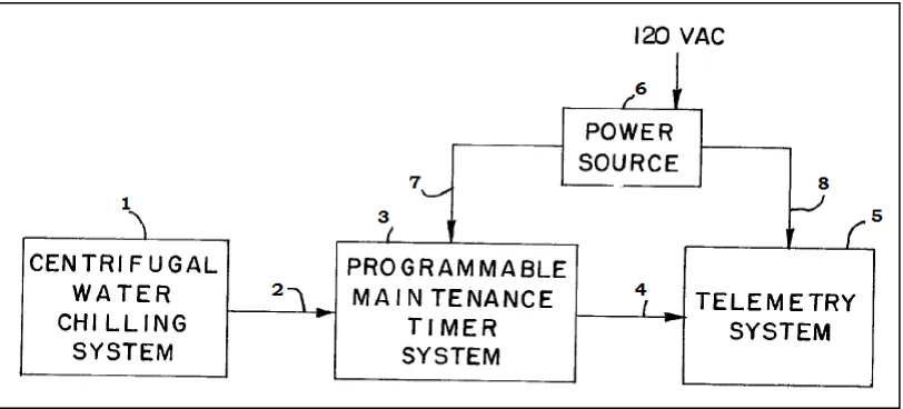
Figure 2.1 shows an overall block diagram of a programmable maintenance timer system of the present invention interconnected to a centrifugal water chilling system
and a telemetry system. This programmable maintenance timer system is generally designed by reference numeral 3 and receives an input signal from centrifugal water
chilling system 1 and line 2. An output signal is then generated on line 4 for delivering it to a telemetry system 5. A power source 6 has its output applied to the timer system via the line 7 and to the telemetry system 5 via line 8. Its input is 120 VAC.
Figure 2.1: Overall block diagram of a programmable maintenance timer system (John C. Hansen, Spring Grove, Lioyd A. Johnson, Dover, 1985)
10
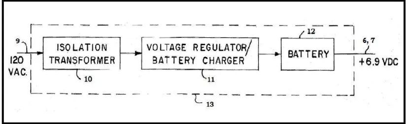
Figure 2.2: A block diagram showing in more detail the power source 6 illustrated in Figure 2.1 (John C. Hansen, Spring Grove, Lioyd A. Johnson, Dover, 1985)
Scott R. Wheeler, Dominic Baulier (2010) invented a revolution counter for turning assemblies. This revolution counter generally relates to a tool and associated method for keeping accurate count of the number of turns that a driving part, example: a wrench is used to drive or turn a driven part such as a shaft or gear. Particularly, it is directed to a mechanical revolution counter for keeping track of the number of turns a driven part is driven for adjustment to a target or optimal position. A memory
counter circuit maintains a count of turns and increments of the driven part by the driving part, and a reference setting circuit sets a reference setting of the memory counter circuit when a count is to be taken. The device body has a first portion mounting the adapter shaft with the rotary encoder, an intermediate housing containing the memory counter circuit, and a second portion at a distance from the first portion and of a sufficient mass that acts to orient the device body to a gravity-determined position as a reference position. The memory counter circuit receives output signals from the rotary encoder circuit and maintains a count relative to a reference position of the device body.