Experimental Investigation of
Emission from a Light Duty
Diesel Engine Utilizing Urea
Spray SCR system
Noreffendy Tamaldin
PhD
June 2010
The work contained within this document has been submitted
EXPERIMENTAL INVESTIGATION OF
EMISSION FROM A LIGHT DUTY
DIESEL ENGINE UTILIZING
UREA SPRAY SCR SYSTEM
NOREFFENDY TAMALDIN, M.Eng.
A thesis submitted in partial fulfilment of the University’s requirements for the
Degree of Doctor of Philosophy
ii
This thesis is the culmination of over three years of research at AEARG (Automotive Engineering
Applied Research Group), Coventry University. It is over three years of which I have survived only
through the help and understanding of many people. I would like to thank them here. First and
foremost, I would like to express my appreciation to the AEARG director who is also my supervisor
Professor S.F. Benjamin for offering me this enriching opportunity and experience to pursue my
Ph.D. I would also like express my gratitude for his untiring patience and encouragement when
obstacles and difficulties arise, guidance in my research, and for his good example that urges me
to progress academically and personally.
I would also like to convey my invaluable thanks to Dr. C. A. Roberts, for her indispensable
guidance and kind support, her involvement in the project, continuous advice, support and useful
discussions. Without all of these, this work may not have been completed. Special thank Dr. A.J.
Alimin for training me on setting up and running the test bed, analyzers and the Froude control
system. To Dr S. Quadri for calibration and setting up the Ricardo air flow meter. To Mr. R.
Gartside, thank you for his help during the commissioning of the engine, test bed and the engine
control system. To Mr E. Larch for the engine ECU programming and Gredi setup. To Mr S.
Goodall (Brico) for his technical advice. The technical help and assistance from, Mr C.
Thorneycroft, Mr. S Allitt, Mr. C. Roebuck and the late Mr. K.Smith are also appreciated and
acknowledged.
I am indebted to UTeM and MOHE (Ministry of Higher Education), Malaysia for providing the
financial support throughout my study and the following companies: Jaguar Land Rover, Johnson
Matthey Catalyst and Faurecia, for their technical provisions for the experimental works.
I cannot end without thanking my family on whose constant encouragement and love I have relied
throughout my study, especially my parents, Tamaldin Bahardin and Zaiton Husin for their love
and emotional support. My gratitude also goes to my Faculty Dean, Professor Dr Md. Razali Ayob,
for believing in me and his continuous moral support to make sure I complete my study.
Last but not least, my deepest love and appreciation to my dearest wife, Maseidayu Zolkiffili and
my wonderful kids, Ameer Husaini and Amaar Zuhasny, for their passion and suffering being with
me in the challenging weather and life in the UK throughout my study. They are all the reason I
iii
Stringent pollutant regulations on diesel-powered vehicles have resulted in the development of new
technologies to reduce emission of nitrogen oxides (NOx). The urea Selective Catalyst Reduction (SCR) system
and Lean NOx Trap (LNT) have become the two promising solutions to this problem. Whilst the LNT results in a
fuel penalty due to periodic regeneration, the SCR system with aqueous urea solution or ammonia gas
reductants could provide a better solution with higher NOx reduction efficiency.
This thesis describes an experimental investigation which has been designed for comparing the effect NOx
abatement of a SCR system with AdBlue urea spray and ammonia gas at 5% and 4% concentration. For this
study, a SCR exhaust system comprising of a diesel particulate filter (DPF), a diesel oxidation catalyst (DOC) and
SCR catalysts was tested on a steady state, direct injection 1998 cc diesel engine. It featured an expansion can,
nozzle and diffuser arrangement for a controlled flow profile for CFD model validation. Four different lengths
of SCR catalyst were tested for a space velocity study. Chemiluminescence (CLD) based ammonia analysers
have been used to provide high resolution NO, NO2 and NH3 measurements across the SCR exhaust system. By
measuring at the exit of the SCR bricks, the NO and NO2 profiles within the bricks were found. Comparison of
the measurements between spray and gas lead to insights of the behaviour of the droplets upstream and
within the SCR bricks.
From the analysis, it was deduced that around half to three quarters of the droplets from the urea spray
remain unconverted at the entry of the first SCR brick. Approximately 200 ppm of potential ammonia was
released from the urea spray in the first SCR brick to react with NOx. The analysis also shows between 10 to
100 ppm of potential ammonia survived through the first brick in droplet form for cases from NOx-matched
spray input to excess spray. Measurements show NOx reduction was complete after the second SCR bricks.
Experimental and CFD prediction showed breakthrough of all species for the short brick with gas injection due
to the high space velocity. The long brick gas cases predictions gave reasonable agreement with experimental
results. NO2 conversion efficiency was found higher than NO which contradicts with the fast SCR reaction
kinetics.
Transient response was observed in both cases during the NOx reduction, ammonia absorption and desorption
process. From the transient analysis an estimate of the ammonia storage capacity of the bricks was derived.
The amount of ammonia slippage was obtained through numerical integration of the ammonia slippage curve
using an excel spreadsheet. Comparing the time constant for the spray and gas cases, showed a slightly faster
iv
CHAPTER TITLE PAGE
ACKNOWLEDGEMENTS………. ii
ABSTRACT……….……….………..…. iii
TABLE OF CONTENTS……….…. iv
LIST OF TABLES ………..………... x
LIST OF FIGURES ……….……….…. xi
LIST OF ABBREVIATIONS AND SYMBOLS………... xiv
LIST OF APPENDICES ……….………….... xx
CHAPTER 1 : INTRODUCTION ... 1
1.0 Background of Air pollution. ... 1
1.1.1 History of Pollution ... 1
1.1.2 Diesel Emission Regulation. ... 3
1.2 Motivation of this thesis ... 4
1.2.1 Aims and Objectives ... 4
1.2.2 Thesis Organisation ... 5
CHAPTER 2 LITERATURE REVIEW... 6
2.0 Diesel After-treatment on NOx Emission Overview ... 6
2.1 Principle of Operation: Selective Catalyst Reduction (SCR) ... 6
2.2 Diesel Oxidation Catalyst (DOC) and Diesel Particulate Filter (DPF) ... 8
2.2.1 Effect of NO2/NO ratio on NOx conversion. ... 12
2.3 SCR Catalyst types ... 13
2.3.1 Platinum catalysts ... 13
2.3.2 Vanadia Titania Catalysts ... 14
v
2.3.3.1 Low temperature Zeolite ... 15
2.3.4 Comparison of SCR catalysts. ... 16
2.4 SCR reductants ... 17
2.4.1 Aqueous Ammonia ... 17
2.4.2 Anhydrous ammonia. ... 20
2.5 Challenges in automotive SCR. ... 20
2.5.1 Ammonia slip ... 21
2.5.2 Uniform mixing of Urea. ... 21
2.5.4 Space velocity ... 22
2.5.5 Light duty diesel engine study ... 22
2.5.6 Urea spray droplet modelling ... 22
CHAPTER 3: RESEARCH METHODOLOGY ... 25
3.0 Introduction ... 25
3.1 Engine Commissioning and Setup ... 25
3.1.1 Engine Commissioning and Setup for Steady State Test. ... 25
3.1.2 Engine Dynamometer ... 27
3.1.3 Engine mass flow rate measurement ... 27
3.2 Final SCR Exhaust build and commissioning. ... 28
3.2.1 SCR Exhaust Fabrications and Specifications. ... 30
3.2.2 DPF-DOC assembly. ... 30
3.2.3 SCR Catalysts Assembly ... 31
3.2.4 Urea Spray Mixing Chamber ... 32
3.2.5 Instrumentation module assembly. ... 33
3.2.6 Long and short diffuser assembly ... 34
3.2.7 Bypass pipe assembly. ... 34
vi
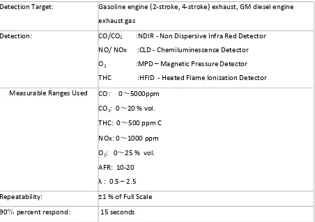
3.3 EXSA 1500 NOx Analyser Setup ... 35
3.3.1 EXSA 1500 Specifications and Resolutions ... 35
3.3.2 Gas requirements and Calibration Gases ... 36
3.3.3 NOx measurement procedure ... 37
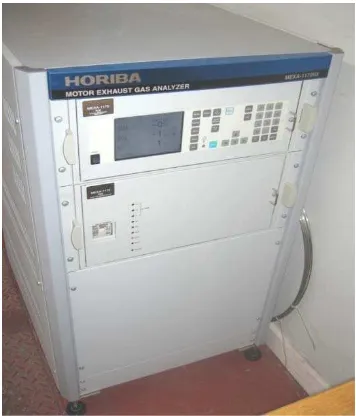
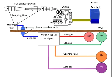
3.4 Ammonia analyser MEXA 1170Nx ... 38
3.4.1 MEXA1170Nx Specification and Resolution. ... 39
3.4.2 MEXA 1170Nx Gas Requirements and Calibration. ... 40
3.4.3 MEXA 1170Nx Working Principles ... 43
3.4.3a Working Principle of Chemiluminescence (CLD) ... 43
3.4.3b Interference of CO2 and H2O ... 44
3.4.3c Measurement of NOx ... 44
3.4.4 NOx measurement in NH3 mode. ... 45
3.4.5 NO2 measurement in NO2 mode. ... 45
3.5 ETAS Lambda Meter ... 46
3.6 Urea Spray Setup ... 47
3.6.1 Urea Spray Calibration ... 48
3.6.2 Urea Spray Pulse Length Setting Procedure ... 49
3.6.3 Engine NOx Out Mapping ... 49
3.6.4 The Urea Spray Layout and Experimental Procedure ... 52
3.6.5 Spray Setting and Cleaning Procedures. ... 54
3.6.6 Deposit build up on Spray ... 56
3.6.7 Cleaned Spray inspection ... 57
3.7 NH3 Gas Experimental Setup ... 59
3.7.1 NH3 Gas Supply and Nozzle Location. ... 59
3.7.2 Gas flow meter and pressure gauge. ... 60
vii
3.8 NO/NO2 measurement for DPF-DOC arrangement. ... 63
3.8.1 DOC-DPF configuration. ... 63
3.8.2 DPF-DOC configuration. ... 64
3.9 Measurement using various sampling probe length. ... 66
3.10 Problems associated with the MEXA Analyser ... 68
3.11 Final measurement strategies. ... 73
3.12 Summary of final experimental procedures. ... 76
3.13 Example of measurements strategy applied ... 77
CHAPTER 4: EXPERIMENTAL RESULTS AND DISCUSSIONS ... 79
4.0 Experimental results: Introduction ... 79
4.1.0 Urea spray studies: General overview ... 79
4.1.1 Urea spray studies: Upstream Measurements (1 and 4 SCR bricks) ... 80
4.1.2 Urea spray studies: Downstream Measurements (1 and 4 SCR bricks) ... 80
4.1.3 Urea spray studies: Deduced value... 81
4.1.4 Urea sprays studies: Ammonia levels. ... 81
4.1.5 Measurement with Urea Spray and 1 SCR bricks. ... 82
4.1.6 Measurement with Urea Spray and 4 SCR bricks. ... 83
4.2 Ammonia gas studies: General Overview ... 84
4.2.1 Ammonia gas studies: upstream measurements. (1 and 4 SCR bricks) ... 84
4.2.2 Ammonia gas studies: downstream measurements. (1 and 4 SCR bricks) ... 85
4.2.3 Ammonia gas studies: Deduced values... 85
4.2.4 Ammonia gas studies: Ammonia levels ... 86
4.2.5 Measurement with 5% Ammonia Gas and 1 SCR brick. ... 87
4.2.6 Measurement with 5% Ammonia Gas and 2 SCR bricks. ... 87
4.2.7 Measurement with 5% Ammonia Gas and 3 SCR bricks. ... 88
viii
4.3 Analysis of measurement results against ammonia input/potential ammonia input. ... 91
4.4 Analysis of spray compared to gas ... 92
4.5 Analysis of insight behaviour of droplet from the urea spray. ... 93
4.5.1 Ammonia released from urea spray upstream of the SCR bricks. ... 93
4.5.2 Ammonia released from urea spray within the 4 SCR bricks... 94
4.5.3 Ammonia passing through 1 SCR brick in droplets form. ... 94
4.6 Analysis of NO and NO2 conversion efficiency and ammonia slip. ... 95
4.6.1 NO conversion efficiency ... 96
4.6.2 NO2 conversion efficiency ... 97
4.6.3 Comparison of NO and NO2 conversion. ... 98
4.6.4 Ammonia slip. ... 99
4.7 CFD modelling analysis comparison with measurements. ... 100
4.7.1 CFD data comparison with ammonia gas injection for 1 SCR and 4 SCR bricks. ... 101
4.8 Comparison of CFD prediction with NO2, NO and NH3 at the SCR exit. ... 102
4.8.1 CFD prediction comparison of NO2 with measurement results... 102
4.8.2 CFD prediction comparison of NO with measurement results. ... 103
4.8.3 CFD prediction comparison of NH3 with measurement results. ... 103
4.8.4 Overall remark from CFD comparison with measurements. ... 104
4.9 Transient analysis in the investigation. ... 105
4.9.1 Transient analysis of 4 SCR bricks with 4% NH3 gas. ... 105
4.9.1.1 Time constants for gas. ... 108
4.9.2 Transient analysis of 4 SCR brick with urea spray ... 109
4.9.2.1 Time constants for urea spray. ... 111
4.9.3 Comparison of the urea spray and ammonia gas transients. ... 111
ix
5.0 Conclusions and Future work: Introduction. ... 114
5.1 DPF-DOC arrangement. ... 114
5.2 Experimental techniques. ... 114
5.3 Behaviour of urea droplet from spray. ... 115
5.4 Space velocity and resident time effect. ... 115
5.5 Transient observation and storage. ... 115
5.6 Significant of findings in chapter 4 ... 116
5.7 Contributions to the knowledge ... 116
5.8 Recommendation for Future Work. ... 117
5.8.1 Improved gas analyser to measure NOx in presence of ammonia. ... 117
5.8.2 Spray dosing system... 117
5.8.3 Cleaning of spray or continuous spraying ... 118
5.8.4 Improved warm up and system using sequential program. ... 118
5.8.5 Signal trigger improvement with level differentiation of spray pulses and gas settings. ... … 118
5.8.6 Investigation of effect of spray angle and positions. ... 118
5.8.7 Moving from 1D to 3D flow ... 118
5.8.8 Transient study (acceleration and deceleration) ... 119
5.8.9 Engine Mass flow rate measurement and logging... 119
REFERENCES ... 120
x
TABLE TITLE PAGE
1.1.2 Evolution of European emission regulations (reproduced from DieselNet 2010)...… 3
2.3.1 Various SCR Catalyst Temperature range. ……….……. 16
3.1.1 Diesel Engine specification used for investigation (Ford 2FM series) ………….………… 26
3.2.2 Detail specification of the DOC catalyst……… 31
3.2.3 Detail specification of the SCR catalyst……….…… 32
3.3.1 Technical Specifications of EXSA 1500 Common gas analyser [Extracted from the Horiba Ltd, EXSA 1500 operating manual Oct 2004] ……… 36
3.4.2 Gas Requirement for MEXA-1170Nx Analyser. ………..……….………… 40
3.8.1 NO/ NO2 ratio based on DOC-DPF assembly. ………..……… 64
3.10a MEXA analyser performance when measuring a mixture of NO, NO2 and NH3….…… 72
3.11a Measurement strategy when using Horiba MEXA 1170Nx ammonia analyser………. 75
3.11b Experimental test matrix with urea spray and NH3 gas……….. 76
4.1.5 Summary of Result: Urea Spray with 1 SCR. ………..……… 82
4.1.6 Summary of Result: Urea Spray with 4 SCR. ……….………. 83
4.2.5 Summary of Result: 5% Ammonia Gas with 1 SCR. ……….. 87
4.2.6 Summary of Result: 5% Ammonia Gas with 2 SCR. ……… 88
4.2.7 Summary of Result: 5% Ammonia Gas with 3 SCR. ……… 89
4.2.8 Summary of Result: 5% Ammonia Gas with 4 SCR. ……… 90
4.2.9 Summary of Result: 4% Ammonia Gas with 1 SCR……… 91
4.6.1 Space velocity for SCR bricks used in the investigation. ……… 97
xi
FIGURE TITLE PAGE
1.1.1 Increasing popularity of diesel powered vehicle in the United Kingdom (reproduced
from SMMT Motor Industry Fact 2010)……….…..…….……..…..….……... 2
1.1.2 Euro 6 (2014) LDD NOx regulations compared to US Tier 2 Bin 5 and California SULEV (Bin2). [Johnson T.V. 2009]………..…….……..…..….……....…..…….……..…..…..……... 4
2.1 SCR system configurations with open loop urea SCR system [DieselNet 2005]……….…… 8
2.2 Wall-Flow DPF [reproduced from Heck 2009] ..……..……….………..…………. 9
2.2a Possible architecture for NOx/PM control.……..………..….……...……..………..…. 10
2.2b Schematic of an advance diesel after treatment system architecture compared in Gurupatham et al (2008) .……..………..….…..……..……….………..………..…... 10
2.2c Advance diesel after treatment system with SCRF concepts [Guo et al 2010] ……….……. 11
2.2.1a Effect of NO2/NO ratio on NOx conversion in V2O5/TiO2 catalyst ……….……….. 12
2.2.1b Effect of NO2 from DOC on NOx conversion……….… 13
2.3 Comparison of SCR catalyst operating temperature windows [Walker 2005]………... 16
2.4.1a Urea solution freezing point [BASF 2003]……….………... 19
2.4.1b Urea solution 32.5% decomposition [BASF 2003]……….. 19
3.1.1 The 2FM series engine with Injection Control Unit (ICU) and Engine Control Unit (ECU) on Froude Consine AG150 engine dynamometer……….……..………..…. 26
3.1.4 Ricardo mass flow meter measuring engine Mass Flow Rate (MFR)……….……….… 28
3.2 Final assembly of the SCR exhaust system……….……….. 29
3.2.1 The suspended exhaust from a square metal frame.………..….………... 30
3.2.4 The Urea spray mixing chamber……….…….……..……….... 32
3.2.5 Instrumentation modules location along the SCR exhausts system………….……..………….. 33
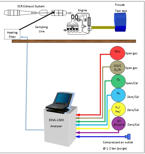
3.3.2 EXSA 1500 NOx analyzer gas piping configuration……….……..……….. 37
3.4 The MEXA-1170Nx NH3 analyzer unit……….……..……….. 39
3.4.2 Gas piping Layout for MEXA-1170NX ammonia analyzer……….……..………..……… 41
3.3.4 Process flow of MEXA-1170NX daily operation and calibration……….………..…… 42
3.4.4 NH3 mode of MEXA-1170NX analyzer……….……….….. 45
3.4.5 NO2 mode of MEXA-1170NX analyzer……….……..………. 46
3.5 ETAS LA4 Lambda meter used to measure O2 before and after the SCR catalysts……..… 47
xii 3.6.2 Chart showing estimated urea/AdBlue (g/s) required against engine NOx out (ppm)…. 49
3.6.3a Engine NOx out based on load BMEP (bars), speed (RPM) and EGR ON………... 50
3.6.3b Exhaust Mass Flow (g/s) based on load, BMEP (bars), speed (RPM) and EGR ON……….. 50
3.6.4a Urea AdBlue injector testing prior to experimental with spray system……… 52
3.6.4b Urea Spray injector and supply pipes and wiring in place……….… 53
3.6.4d Urea spray system experimental layout………. 54
3.6.5a Spray cleaning procedures flow chart……….………. 55
3.6.6 White deposit build up and ultrasonic cleaning………... 56
3.6.6e Manual cleaning of injector sleeve with tweezers………...……….. 57
3.6.7 Final visual inspection of fully cleaned injector……….………... 58
3.7.1b NH3 gas injection nozzle………...……….… 60
3.7.2 Gas flow meter reading as a guide.……….. 61
3.7.3 NH3 gas experimental layout………..………... 62
3.8.1 Initial configuration with DOC-DPF assembly.………..……….… 64
3.8.2 Final DPF-DOC assembly………..………. 65
3.9a Variation of sampling probe length for profile measurement……….…….. 66
3.9b Long (55 mm) sampling probe………..……… 67
3.9c Medium (25 mm) sampling probe………..………... 67
3.9d Check point with medium sampling probe for gas measurement.……….……….… 68
3.10a Rubber seal disintegrate in the SUM NOx converter.………..…….… 69
3.10.1b Paper based finger filter located at the back of MEXA 1170Nx ammonia analyser……... 69
3.10c Spherical carbon compact NOx converter………..….……….………… 70
3.10d New glassy carbon NOx converter………..………….……….… 70
3.10e A typical example of erroneous measument of NOx in present of ammonia………..… 71
3.13 Example of engine log from 5% ammonia gas with 1 scr brick.……….……… 78
4.1a Typical example of erroneous measument of NOx in present of ammonia.………...……… 78
4.3 Summary of measurement with 1 and 4 SCR bricks.………..……….. 92
4.5.1 Ammonia released from spray upstream of the SCR bricks……….……… 93
4.5.2 Ammonia released from urea spray within 4 SCR bricks.………..……… 94
4.5.3 Ammonia passing through 1 SCR brick in droplets form. ……….…….……… 95
4.6.1 NO conversion with respect to SCR length………...…..………..……… 96
xiii
4.7.1a CFD and data comparison for species level at exit from 1 SCR brick.………..………… 101
4.7.1b CFD and data comparison for species levels at exit from 4 SCR bricks.……… 101
4.8.1 Simulations of NO2 against measurements at SCR exit.……… 102
4.8.2 Simulations of NO against measurements at SCR exit.……….………. 103
4.8.3 Simulations of NH3 against measurements at SCR exit. ……….……… 104
4.9.1 Sample of transient response in 4 SCR bricks with 4% NH3 gas……… 105
4.9.1a Transient analysis for 4% gas with 4 SCR………..………..………… 106
xiv
α - Alpha – ratio of NH3 : NOx
λ - Ratio between actual AFR and stoichiometric AFR
ACEA - European Automobile Manufacturers Association
AdBlue - Registered trademark for AUS32 (Aqueous Urea Solution 32.5%)
AEARG - Automotive Engineering Applied Research Group, Coventry University
AFR - Air Fuel Ratio
Al+3 - Aluminium cations
Al2(SO4)3 - Aluminium Sulfate
Al2O3 - Aluminium Oxide
AMI - AdBlue supplier - Agrolinz Melamine International (Austria)
Anatase - One of the three
develope
of titanium dioxide, it crystallizes in the
ARB - Air Resource Board
ASAM - Association for Standardization of Automation and Measuring Systems
AUS32 - Aqueous Urea Solution 32.5% by weight.
BaO - Barium Oxide is a white Hygroscopic Compound Formed by the Burning of Barium in Oxigen.
BASF - AdBlue supplier, German Chemical Company,
Badische Anilin und Soda Fabrik (Baden Anilin and Soda Factory)
xv
BSP - British Standard Pipe Taper thread
CAE - Computer Aided Engineering
CAFE - Corporate Average Fuel Economy
CAL - Calibration
CAN - Controller Area Network (computer network protocol and bus standard
designed to allow
other and without a host
CARB - California Air Resource Board
-
CFD - Computational Fluid Dynamics
CLD - Chemiluminescence Detector
CNG - Compressed Natural Gas is a fossil fuel substitute for gasoline (petrol),
diesel, or propane
CO - Carbon Monoxide
CO2 - Carbon Dioxide
CRT - Continuously Regenerating Technology filter
Cu - Copper
DEF - Diesel Exhaust Fluid
DIN 70070 - German Industrial Standard on Specification of SCR Urea Grade,
(DIN-Deutsches Institut für Normung. German Institute for Standardization)
DOC - Diesel Oxidation Catalysts
DPF - Diesel Particulate Filters
dSPACE - A software package integrated with Matlab Simulink use to control the
xvi
ECU - Engine Control Unit
EEC(CED) - European Commission Directive
EGR - Exhaust Gas Recirculation
EMS - Engine Management System
EPA - Environmental Protection Agency, United States
ESC - European Steady Cycle
FAN MOG Fleet Average Non-methane Organic Gases
FBC - Fuel Borne Catalyst
GHG - Green House Gases
GREDI - Engine ECU calibration software from Kleinknecht Automotive GmbH
GVWR - Gross Vehicle Weight Rating
H2O - Water
HC - Hydrocarbon
HLDT - Heavy light-duty trucks
HNCO - Isocyanic Acid
ICU - Injection Control Unit
JAMA - Japan Automobile Manufacturers Association
JARI - Japan Automotive Research Institute
kW - Kilowatt (Power)
LDD - Light Duty Diesel
LDT - Light Duty Truck
xvii
LEV II - Low Emission Vehicle II
LLDT - Light light-duty Trucks
LNT - Lean NOx Trap
LPG - Liquid Petroleum Gas
MAF - Intake air Mass Air Flow
MECA - Manufacturer of Emissions Control Association
MKT - Market
MLW - Maximum Laden Weight
MoO3 - Molybdenum trioxide
N2 - Nitrogen gas
NAAQS - National Ambient Air Quality Standard
NGV - Natural Gas Vehicle
NH2 - Amines are organic compounds and functional groups that contain a basic
nitrogen atom with a lone pair
NH3 - Ammonia
NH4 - Ammonium
NMHC - Non-methane Hydro Carbon. All Hydrocarbons excluding methane.
NMOG - Non- methane Organic Gases. All Hydrocarbons and Reactive Oxygenated
Hydrocarbon Species such as Aldehydes, but excluding Methane
NOx - Nitrogen Oxides ( NO and NO2)
NPT - National Pipe Thread Tapered Thread (NPT) is a
threads.
xviii OEHHA - The Office of Environmental Health Hazard Assessment (California EPA)
OGU - Ozone Generator Unit
Pb - Lead
PEL - Permissible Exposure Level
PM - Particulate Matters
ppm - Parts per million
Pt - Platinum
PZEV - Partial Zero Emission Vehicle.
RPM - Speed in Revolution per Minute
Rutile - 2.
SAE - Society of Automotive Engineers
SAE J1088 - SAE J1088 - Test Procedure for the Measurement of Gaseous Exhaust
Emissions From Small Utility Engines
SCR - Selective Catalyst Reduction
SCRF - Combination of SCR and DPF with SCR washcoat on a DPF (Ford Motor)
SMMT - Society of Motor Manufacturers and Traders, UK Limited.
SO2 - Sulphur Dioxides
SO3 - Sulphur Trioxides
SOF - Organic Fraction of Diesel Particulates
STAR-CD - A CFD software package from CD-Adapco
SULEV - Super Ultra Low Emission Vehicle
xix
TiO2 - Titanium Dioxide
TLEV - Transitional Low Emission Vehicle.
ULEV - Ultra Low Emission Vehicle
UN ECE - United Nation European Cycle Emission
US, EPA - United States, Environmental Protection Agency
V2O5 - Vanadium Oxides
VGT - Variable Geometry Turbocharger
VPU - Vacuum Pump Unit
WHTC - World Harmonized Transient Cycle
WO3 - Tungsten trioxide
ZSM-5 - Zeolite Sieve of Molecular Porosity (or Zeolite Socony Mobil)-5. It is a
xx
APPENDIX
Reference section numbered in thesis
TITLE PAGE
3.1.1 Power curve for Ford 2.0 cc diesel engine A-1
3.1.3 Ricardo mass flow meter calibration A-2
3.2 Supplied parts for SCR exhaust build A-3
3.2b List of drawing for SCR exhaust system A-4
3.4.1 MEXA 1170Nx specification A-5
3.5 Lambda sensor LA4 connection configuration A-6
3.6.2 Potential ammonia released from urea spray calculation A-7
3.7a Calibration chart for NH3 gas flow rate using glass float A-8
3.7b Calibration chart for NH3 gas flow rate using stainless steel float A-9
3.7.1 Summary of gas flow rate with 4% and 5% ammonia in balance N2 A-10
3.7.1a Calculation of gas flow rate with 4% ammonia in N2 with steel float A-11
3.7.1b Calculation of gas flow rate with 4% ammonia in N2 with glass float A-12
3.7.1c Calculation of gas flow rate with 5% ammonia in N2 with steel float A-13
3.7.1d Gas flow setting/spray setting vs. ammonia level produced A-14
4.0 List of appendices from chapter 4 : Experimental Results B-1
4.1.5 Result from Urea spray : 1 SCR B-2
4.1.5b SUM in and SUM out average for 1 SCR with spray B-3
4.1.6 Result from Urea spray : 4 SCR B-4
4.1.6b SUM in and SUM out average for 4 SCR with spray B-5
4.2.5 Result from 5% Gas : 1 SCR B-6
4.2.5b NO dw 1SCR 5% : manual log from MEXA B-6b
4.2.6 Result from 5% Gas : 2 SCR B-7
4.2.7 Result from 5% Gas : 3 SCR B-8
4.2.8 Result from 5% Gas : 4 SCR B-9
4.2.9 Result from 4% Gas : 1 SCR B-10
4.9.1a Excel numerical integration – 4% gas 4 SCR B-11
4.9.2a Excel numerical integration – Urea spray 4SCR B-12
5.0 Publication : SAE World Congress April 2010
Experimental Study of SCR in a Light-Duty Diesel Exhaust to Provide Data for Validation of a CFD Model Using the Porous Medium Approach
(SAE 2010-01-1177)
1
CHAPTER 1: INTRODUCTION
1.0 Background of Air pollution.
At present, there are many sources of air pollution from the combustion of fossil fuel for power
plants, factories, office building, transportation and other. Air pollution can have a large negative
impact on human health and the environment. The United States environmental protection agency
(EPA) has identified six common pollutants including Ozone (O3), Particulate Matter (PM), Carbon
Monoxide (CO), Sulphur Dioxide (SO2), Lead (Pb) and Nitrogen Oxides (NOx). The sum of nitric oxide
(NO) and NO2 is commonly called nitrogen oxides or NOx. Over the past decade, NOx emissions have
become one of the concerns due to its health impact to human. Various studies have been
conducted by numerous agencies around the world to evaluate the negative impact of NOx emission
to human health. The World Health Organization (WHO, 2002) estimated that around 2.4 million people die every year linked to causes directly attributable to air pollution. A study at Birmingham
University also revealed a strong correlation between deaths by pneumonia and traffic emissions in
England. (Knox, E.G. 2008)
1.1.1 History of Pollution
The environmental impact of automotive pollution has led governments to enforce automotive
manufacturers to reduce quantities of tail-pipe emissions. Developments of the modern automotive
catalytic converter and engine management systems have been in response to these requirements.
There are an increasing number of vehicles in the world today with an estimate at around 800
million [Preschern et al, 2001]. The history of the new vehicle population over a ten year period in the United Kingdom shows the growing popularity of diesel powered vehicles over petrol since 2003.
This is shown in figure 1.1.1. The rise of fuel prices and the advantages of diesel-powered vehicles in
2 Figure 1.1.1 Increasing popularity of diesel powered vehicle in the United Kingdom (reproduced from
SMMT Motor Industry Fact 2010)
1.1.2 Diesel Emission Regulation.
Diesel Emission control began in the mid 1980’s when the United States, Environmental Protection
Agency (EPA) and California Air Resource Board (CARB) starting to consider emission from on road
vehicles. It started after a growing popularity of diesel engine patented by Rudolf Diesel in 1892 for
replacing steam engines. In the past, only Carbon Monoxide (CO) and Hydrocarbon (HC) emission
from gasoline engines were regulated [Heck, 2009].
The Three-Way
ignition internal combustion engines operating at stoichiometric air-fuel ratio(typically fuelled by
at O2 levels in excess of 1.0%, and do not function well at levels above 0.5%. Since diesels operate
with excess oxygen, TWC cannot be utilized to reduce NOx and alternative after treatment
3 In developed countries, automobiles must comply with statuary emission regulation to stay
road-worthy. These are measured over a standard drive-cycle, typical of mixed driving conditions. A
summary of the evolution of European emissions standards shows that future legislation will place
even tighter restrictions on automotive emissions with Euro 6 NOx level at only 0.08 g/km. The
evolution of European emission regulations is shown in the table 1.1.2.
Table 1.1.2 Evolution of European emission regulations (reproduced from DieselNet 2010)
Future legislation cannot be achieved in a cost-effective manner with current diesel after treatment
technology; consequently, the prospect of reducing emissions without substantially increasing
vehicle cost is attractive to manufacturers. Therefore, significant efforts have been driven to further
improve the diesel after treatment. Automotive manufacturers have been tested with reducing NOx
4 Figure 1.1.2 Euro 6 (2014) LDD NOx regulations compared to US Tier 2 Bin 5
and California SULEV (Bin2). (Johnson T.V. 2009)
1.2 Motivation of this thesis
The main motivation in this investigation is that the collaborating automotive manufacturers
working with the Automotive Engineering Applied Research Group (AEARG) at Coventry University
are required to find a cost effective diesel after treatment system to further reduce NOx pollution
from light duty diesel powered passenger cars.
1.2.1 Aims and Objectives
The thesis aims and objectives are:
• To investigate the SCR performance on a Light Duty Diesel (LDD) engine.
Most of the current SCR investigations are focused on Heavy Duty Diesel (HDD) engines. This
5
• To utilized zeolite in the SCR exhausts system.
Relatively few studies have been conducted on zeolite catalysts. Historically vanadium catalysts have
been used for SCR.
• To develop a unique test facility and provide a database for CFD validation.
The SCR exhaust system built in this investigation provides an excellent opportunity for assessing the
performance of simulation models.
• To develop a simplified controlled SCR exhaust system with real engine on test bed.
Most of SCR investigations use laboratory reactor and very little information is available from SCR
system on real engine test beds. The experience gained in this investigation will be useful for future
development.
1.2.2 Thesis Organisation
The organization of the thesis corresponds to the four objectives above.
Chapter 2 reviews current understanding of SCRs and examines the relation between NOx reduction and NO/NO2 ratio.
Chapter 3 addresses the setting up of experiments, instrumentation and test protocol in order to achieve the objectives above.
Chapter 4 presents and discusses the results obtained from the ammonia gas and urea spray experiments.
6 CHAPTER 2: LITERATURE REVIEW
2.0 Diesel After-treatment for NOx reduction
Recent advancement in diesel after-treatment has identified two key promising technologies for reducing diesel emission which are the Lean NOx Trap ( LNT) and Selective Catalyst Reduction (SCR) [Spurk et al., 2007]. D espite much research, improvements are n eeded in c onversion efficiency across wider temperature ranges.
Alimin et al., (2006) explored the performance of an LNT at the Automotive Engineering Applied Research Group (AEARG), Coventry University. Whilst good NOx reduction was achieved the LNT system results in a fuel penalty due to regeneration period where rich combustion is needed to purge th e tr ap. I n c ontrast, th e S CR s ystem p rovides a n a lternative solution wi thout an associated fuel penalty.
2.1 Principle of Operation: Selective Catalyst Reduction (SCR)
Selective catalytic reduction (SCR) is a means of removing nitrogen oxides, through a c hemical reaction between the exhaust gases, a (reductant) additive, and a catalyst. Beeck et al., (2006)
suggestedthe use of gaseous or liquid
to a stream of the exhaust stream to form harmless H2O (vapour) and N2.
Three main processes involved in the SCR technology involve thermal decomposition, hydrolysis and three NOx reduction SCR reactions. The three SCR reactions involved are Fast SCR, Standard SCR and Slow SCR reaction.
7 Urea d roplets from the s pray e xchange m ass, momentum a nd e nergy with s urroundings h ot exhaust gases leading to vaporization of water.
NH2-CO-NH2 (aqueous) NH2 – CO-NH2 (solid) + 6.9H2O (gas) Equation 2.1a
Schaber et al., (2004) reported that the Solid urea left from equation 2.1a started melting at 1330C and undergoes thermolysis to form ammonia and Isocyanic acid as follows:
NH2 – CO-NH2 (solid) NH3 (gas) + HNCO (gas) Equation 2.1b
Yim S.D. et al., (2004) also s uggested t he h ydrolysis o f I socyanic ac id is fa cilitated b y h igh temperatures a t a round 400oC in t he p resence of a S CR c atalyst. The I socyanic acid w hich is stable in g as f orm u ndergoes h ydrolysis t o f orm a mmonia an d c arbon d ioxide as s hown in equation 2.1c.
NHCO (gas) + H20 (gas) NH3 (gas) + CO2 (gas) Equation 2.1c
Olsson et al., (2008) reported once th e N H3 gas i s av ailable, t he t hree N Ox re duction S CR reactions take place depending on the NOx source. The standard SCR using NO, Fast SCR with NO, NO2 and slow SCR with only NO2 as follows:
(Standard SCR) 4NH3 + 4NO + O2 4N2 + 6H2O Equation 2.1d
(Fast SCR ) 2NH3 + NO + NO2 2N2 + 3H2O Equation 2.1e
(Slow SCR) 4NH3 + 3NO2 3.5N2 + 6H2O Equation 2.1f
Amon et al., (2004) reported good N Ox c onversion efficiency with th e S CR system i n bo th stationary and transient test cycle of Japanese, European and US test cycle.
8 Various S CR c onfigurations have b een u sed b y d ifferent re searchers and o ngoing d evelopment i s still u nderway e specially f or li ght d uty ap plication. A t ypical u rea S CR s chematic f or h eavy d uty is shown i n f igure 2 .1
Figure 2.1 SCR system configurations with open loop urea SCR system [DieselNet 2005].
2.2 Diesel Oxidation Catalyst (DOC) and Diesel Particulate Filter (DPF)
Diesel Oxidation catalyst and particulate filter have been widely used for PM removal in diesel applications. DOC is one of the oldest technologies originated from the early two way catalyst for controlling CO, HC and PM. DOC works by oxidizing unburned species of fuel in the exhaust to h armless p roduct s uch a s C O2 and H2O. D OCs come in m etallic o r c eramic t hrough honeycomb substrates coated with an oxidizing catalyst such as platinum, palladium or both due to low temperature activity for HC conversions [MECA 2007]. Johnson T.V., (2010) highlighted the usage of DOC as being used in more vehicles than any other emission control device. Their critical p resent for t he p roper f unctioning of DPF a nd d eNOx s ystem was als o r eviewed an d continuously evolving.
9 larger than the monolith wall are trapped until the pressure drop across the DPF become too high.
Figure 2.2 Wall-Flow DPF (reproduced from Heck 2009)
However DPFs have limited capability and will eventually fully clog, therefore they need to be periodically regenerated by c ombustion o f t he t rapped P M. T he s oot r equires a m inimum temperature of 500OC for ignition in the absence of a catalyst which the engine exhaust does not frequently o r reliably re ach. A dditional s teps o r m echanism are n eeded t o c lean u p t he trapped PM, reduce the back pressure and restart the trapping cycle. (Heck 2009)
Konstandopoulos et al., (2000) suggested three method of facilitating the DPF regeneration in order t o maintain t he s atisfactory performance of DPF. They involved a ctive, e xternal an d passive regeneration. Th e active r egeneration i nvolved c hanging th e o peration o f th e d iesel engine w hile p assive approach involved m odification o f t he t rap c omposition. E xternal regeneration would be possible with the introduction of an external system to heat up the trap.
10 Figure 2.2a Possible architecture for NOx/PM control (Beeck et al. 2006)
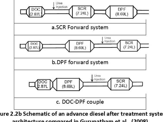
Gurupatham et al., (2008) compared t he i ntegrated D OC-SCR-DPF, D OC-DPF-SCR an d c losed couple DOC-DPF-SCR as shown in figure 2.2b. The DPF forward system shows better PM active regeneration due to being closer to the engine and greater passive regeneration of DOC by NO2. However, DPF forward system disadvantage includes substantially delay of hot gas downstream reducing its SCR light off and the reduction of NO2 by SCR reactions because of soot oxidation by NO2 in the DPF. The close coupled DOC-DPF improved warm up time of DPF and SCR for cold start.
a.SCR Forward system
b.DPF forward system
c. DOC-DPF couple
Figure 2.2b Schematic of an advance diesel after treatment system architecture compared in Gurupatham et al., (2008)
11 simultaneously. However low washcoat loading on SCRF due to backpressure concern, cause the NOx reduction efficiency lower than SCRF placed upstream of SCR catalyst.
Figure 2.2c Advance diesel after treatment system with SCRF concepts (Guo et al., 2010)
Gieshoff et al., (2001) discovered that the SCR catalyst is affected by the unburned diesel fuel therefore s uggested a DOC b e placed upstream t o r emove u nburned h ydrocarbon. Koebel (2002) and Koebel (2001) also highlighted an increased NO2 level can be realized by placing an oxidation catalyst which promotes oxidation of NO. The oxidation catalyst placed upstream of the u rea i njection p oint decreased V 2O5 light o ff t emperature t o as lo w as 1 50OC. Th e disadvantages of this was an increased oxidation of sulphur dioxide and sulfate PM which result from using fuels of higher sulphur content and an increased of ammonium nitrate formation at temperature below 200OC.
12 2.2.1 Effect of NO2/NO ratio on NOx conversion.
Chandler (2000) suggested that the composition of exh aust g ases emission are mostly of NO (from 8 5-95%) an d s mall quantity o f N O2 (5-15%). It wa s r eported th at increasing t he N O2 fraction in the feed gas can im prove low temperature activity of the V2O5 as s hown in figure 2.2.1a
Figure 2.2.1a Effect of NO2/NO ratio on NOx conversion in V2O5/TiO2 catalyst (Chandler, 2000)
Gieshoff (2001) also reported similar performance with CU/ZSM-5 and other low temperature zeolite based catalysts. Narayanaswamy et al., (2008) simulated NO2/NO ratios up to three and implied good conversion over zeolite with excess NO2.
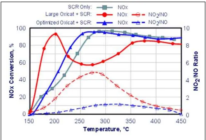
13 However Cooper (2003) suggested that the amount on NO2 must be optimised by suitable sizing and formulation o f the o xidation c atalyst. I f t he NO2 level are too h igh, NOx c onversion efficiency decreases as shown by the red dash line and circles in figure 2.2.1b
Figure 2.2.1b Effect of NO2 from DOC on NOx conversion (Cooper 2003).
Cooper (2003) also suggested a large Pt loading Oxidation catalyst to increase the NO2/NO ratio to nearly 5 (over 80% NO2 in NOx) at around 280OC. As a result, the NOx conversion deteriorated significantly d ue t o d epletion o f am monia s ince t he required NO w as s ubstituted b y N O2 as shown in red line in figure 2.2.1b.
2.3 SCR Catalyst types
The formulation of catalyst is important for the SCR reaction to take place. Three SCR catalysts commonly used are platinum, vanadium and zeolite.
2.3.1 Platinum catalysts
14 suggested that the first SCR catalyst discovered was platinum but with limited usage due to low temperature activity. The effective temperature window fo r platinum was fo und fro m 175 to 250OC[DieselNet 2005]. Due to its poor activity at higher temperature, the other base metal like vanadium and zeolite catalysts were found to be effective at higher temperature windows.
2.3.2 Vanadia Titania Catalysts
Bosch and Janssen (1988) suggested V2O5/Al2O3 catalysts be u sed f or operating temperature higher than 250OC but restricted to sulphur free application due to deactivation of the catalyst from alu mina re action with S O3 forming A l2(SO4)3. T he nonsulphating T iO2 carrier w as recommended for the V2O5. Amon and Keefe (2001) reported extensive studies of V2O5 catalyst supported on TiO2 and WO3 added for HD diesel in Europe with numerous on highway studies. Lambert et al., (2006) highlighted problem with vanadium catalyst which quickly deactivated at high t emperatures a bove 6 00OC therefore s uggested z eolite c atalyst. Th e r ecommended temperature window for vanadium is from 300 to 450OC [DieselNet 2005].
2.3.3 Zeolite Catalysts
Zeolite catalysts were developed to cover a wider range of temperature windows over platinum and vanadium based catalysts. Byrne et al., (1992) suggested zeolite based catalyst to further extend th e operating te mperature a bove 350OC. However t wo t ype of z eolite c atalysts were develop t o c over h igh a nd l ow t emperature w indows. T he h igh temperature z eolite covers temperature windows from 350 to 600OC while the low temperature zeolite covers 150 to 450OC [DieselNet 2005]
2.3.3.1 High Temperature Zeolite
15 Heck (1994) found that zeolite can operate up to 600OC and in the presence of NOx, ammonia was not oxidised to NOx therefore its NOx conversion continually increases with temperature. Therefore the upper temperature limit for this type of zeolite catalysts may be determined by catalyst durability rather than selectivity. It was suggested that this type of zeolite catalysts may be p rone t o s tability p roblems a t h igh te mperature wi th th e p resence of water v apour. F or excessive temperature above 600OC in a h igh water content zeolite tends to deactivate by de-alumination where Al+3 ion in the SiO
2-Al2O3 migrated out of the structure leading to permanent
deactivation and in extreme cases collapsed the crystalline structure.
Lambert et al., (2006) suggested th e i mportance of t hermal d urability of z eolite c atalysts particularly w ith t he in tegration w ith D PF with f orced r egeneration. Th e z eolite catalyst is capable of withstanding temperature above 650OC and brief exposure to temperature of 750 -850OC. Theis (2009) recommended Fe-zeolite catalyst for NOx control at high temperature from 400-600OC. Giovanni et al., (2007) found Fe-zeolite have higher NOx conversion above 350OC with no significant N2O produced and suggested not to exceed 925OC
2.3.3.1 Low temperature Zeolite
Gieshoff (2001) and Spurk et al., (2001) suggested th at a d ifferent t ype of l ow temperature zeolite catalyst could be developed for mobile engine application. I n the 1990s, research was conducted f or t he f ormulation o f C u-exchanged Z SM-5 z eolite als o k nown as a lean-NOx catalyst. The Cu/ZSM-5 was active in reducing NOx within a temperature range of 200 to 400OC but w ith in sufficient thermal d urability. T his le d to a new f ormulation b y modifying t he i on-exchanging of zeolite to undisclosed transition metals. The normal NOx reducing activity for this catalyst was low and the final low temperature zeolite was thermally stable up to 650OC. This formulation has been designed specifically for NO2 gases which significantly improved its NOx conversion a nd extended the temperature wi ndow with N Ox r eduction e fficiency b etter t han 90% over a temperature range of 150-500OC.
Theis (2009) also suggested C u-Zeolite catalysts as m ore effective f or N Ox control at lo w temperature in the range of 200 to 400OC. Giovanni et al., (2007) again found Cu-zeolite to have higher N Ox c onversion a t tem perature below 3 50OC w ith s ignificant N
2O p roduced a nd
16 2.3.4 Comparison of SCR catalysts.
The basis of SCR catalyst comparison is mainly on the operating temperature windows. Each of the c atalysts has their o wn lim itations an d p roblems an d are continuously redeveloped for further improvement in term of NOx conversion efficiency and thermal durability.
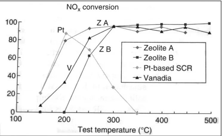
Schmieg et al., (2005) summarized t he p erformance c omparison o f c u-zeolite an d fe -zeolite with vanadium based catalyst to provide useful guidance in the design and operation o f urea SCR N Ox r eduction systems. Th e ef fect of NO: NO2 ratio on s teady state NOx reduction on a typical diesel exhaust temperature of 150 to 500OC was investigated. Transient measurements were performed to determine the impact of NH3: NOx ratio and NH3 storage on catalyst and HC and sulphur poisoning effect.
[image:37.612.121.493.434.662.2]Hamada (2005) reported new formulations with bi-functional catalyst design to simultaneously reduce NOx and oxidize the NH3 slip as well as CO and HC. Walker (2005) compared the SCR catalyst temperature windows for NOx reduction with ammonia and summarized them in figure 2.3. C ontinuous e ffort on c atalyst f ormulation is p rogressing t oward wider t emperature windows, thermal durability, NOx conversion and cost.
17 2.4 SCR reductants
Two most c ommonly used SCR reductants are anhydrous ammonia and aqueous ammonia or urea. Pure a nhydrous ammonia i s extremely toxic and d ifficult t o s afely s tore, b ut n eeds n o further c onversion t o operate w ithin an S CR. It is typically fa vored b y larg e in dustrial S CR operators. A queous a mmonia must b e hydrolyzed in o rder to b e u sed, b ut i t i s s ubstantially safer to store and transport than anhydrous ammonia. Urea is the safest to store, but requires conversion t o a mmonia through t hermal d ecomposition i n order to b e u sed a s a n e ffective reductant [DieselNet 2005].
The aqueous ammonia is also known as AdBlue, Urea Water Solution (UWS) and Diesel Exhaust Fluid (DEF) depending on manufacturers. Eberhard (1994) introduced the use of solid urea but it has received v ery l ittle a cceptance. Hoffman (1996) suggested an alternative t o u rea u sing carbamate salt such as ammonium carbamate, NH2COONH4. Kelly et al., (2006) reported various amines evaluated as SCR reductants which could potentially be generated from diesel fuel and nitrogen.
Alkemade et al., (2006) reviewed the best reductant to be used for SCR system. While ammonia offer slightly better performance, its toxicity and handling difficulty remain the biggest concern. Urea is not as effective but safer to handle which has made it the popular choice for automotive manufacturers. Sullivan et al., (2005) suggested in both form of ammonia it has to be extremely pure d ue t o the fact th at impurities c an c log t he c atalyst. An SCR c atalyst t ypically re quires frequent cleaning even with pure reductants as the reductants can cake the inlet surface of the catalyst w hen the exhaust g as s tream te mperature i s to o l ow f or th e S CR r eaction to o ccur. Research in to reductant t echnology is c ontinuing an d a w ide variety o f alternative re ductant have been explored especially the one with wide availability and a distribution infrastructure in place. [US EPA 2006]
2.4.1 Aqueous Ammonia
18 (aqueous U rea S olution 32.5% b y weight) I t i s a s olution of h igh p urity urea ( 32.5%)in demineralised water (67.5%) used as a supplementary operating fluid (reducing agent) in diesel powered vehicles using selective catalytic reduction (SCR) to improve exhaust emissions. AUS32 is primarily produced in Europe by BASF and AMI, however many other companies manufacture their own similar solution in varying quantities. [BASF 2003]
AUS32 is carried onboard the vehicle in a tank separate to the fuel system and is sprayed into the engine exhaust gases in a special catalytic converter. A typical SCR system uses an amount of AUS32 equivalent to approximately 3 to 5% of the vehicle fuel consumption. In order to ensure effective working o f the SCR system, care must be taken to ensure purity of the catalyst and reducing agent. Any small contaminant can severely reduce the SCR system performance. The manufacturing quality control for AUS32 solutions is governed by DIN standard 70070 [Focus on Catalysts (8), 2, 2005]
SCR systems u sing A dBlue a re currently fitted to many trucks and b uses m anufactured b y Mercedes Benz, Volvo Trucks, DAF Trucks and Iveco, however AdBlue usage as reducing agent is hindered b y its relative availability. S chemes a re u nderway i n E urope but to lesser extents i n Australasia and North America to improve the network distributors for AdBlue and other SCR additive. Internet based tool have been developed to map the locations of AUS32 filling stations reflecting plans for small scale use of SCR system in private vehicle as well as corporate fleets [Focus on Catalysts(2), 3, 2006].
19 Figure 2.4.1a Urea solution freezing point [BASF 2003].
The 32.5% urea solution is a colourless liquid with a faint alkaline reaction. The freshly prepared solutions have a pH of 9 to 9.5. In solution the urea decomposes slowly in room temperature into am monia an d CO2. When th e s olution i s h eated, th e rate of d ecomposition in creases additionally producing biuret [BASF 2003].
Figure 2.4.1b Urea solution 32.5% decomposition [BASF 2003].
20 Problem associated with urea spray have triggered for alternative solution to supply ammonia gas to the SCR system. Elmoe et al., (2006) suggested solid ammonia storage using Mg (NH3)6Cl2 which has high ammonia density very close to urea solution. Taturr et al., (2009) also provide alternative to urea with the use of ammonium carbamate [(NH2-CO2)-(NH4)] in HD diesel which is capable to supply ammonia by heating at a capacity 3 to 4 times more than urea. Therefore, other alternatives than urea to supply ammonia to the SCR system are continuously explored.
2.4.2 Anhydrous ammonia.
The term anhydrous ammonia refers to the absence of water in the material. Ammonia gas is a compound consisting of nitrogen and hydrogen, NH3. It is a colourless gas with pungent odour. Ammonia is widely used in agricultures and contributes significantly to the nutritional needs of terrestrial organisms as by serving as food and fertilizer. The liquid boiling temperature is at -33.34OC and it solidifies at -77.7OC to white crystals therefore the must be stored under high pressure or low temperature [BOC datasheet 2005].
Although w idely used, ammonia gas is classified as toxic and dangerous for the environment. The US EPA has established a guideline for Permissible exposure level (PEL) of 50 ppm in an 8 hours weighted average. Anhydrous ammonia also corrodes copper and zinc containing alloy, therefore brass fittings must be avoided in handling the gas and liquid ammonia can also attack rubber and certain plastics [Yost D.M., 2007]
Recent d evelopment in S CR t echnology c onsiders r eadily av ailable a mmonia gas rat her t han aqueous ammonia solution. Ammonia in g as fo rm can b e s upplied u sing a special s torage container or specially design ammonia storage system.
2.5 Challenges in automotive SCR.
21 calibrated t o g enerate a mmonia f or t he S CR w as als o discussed. Despite p romising N Ox conversion with the SCR system, many other grey areas need attention to further improve the system.
2.5.1 Ammonia slip
Ammonia slip re mains the u ndesired e mission in th e S CR s ystem. It c an b e described as ammonia that exits the SCR system unreacted. Huennekes et al., (2006) suggested 3 ways the injected urea can lead to NH3 slipping out of the SCR catalyst. It involved the incomplete SCR reaction due to NH3: NOx ratio higher than NOx conversion efficiency, the released o f stored ammonia from SCR catalyst and the incomplete decomposition of urea before reaching the SCR catalyst. Girard et al., (2007) also reported NH3 slippage as a result of high NH3: NOx ratio (called alpha). It was suggested reducing the alpha value less than one at low temperature where the ideal alpha is equal to one.
2.5.2 Uniform mixing of Urea.
The urea injection quality and mixing are complex and critically important. In real engine testing such as in this study, uncertainties existed over the uniform mixing of the urea spray with the exhaust gases. Gorbach et al., (2009) introduced urea mixers for mixing of urea droplets from sprays and saw s ystem efficiencies v ary fr om 60 t o 9 5% d epending o n a mmonia d istribution across the catalyst. The urea mixer comes in a variety of types ranging from wire mesh designs to vanes and honeycomb. Breedlove et al., (2008) suggested the use of different nozzle designs to provide different droplet quality with range of characteristics at different injection stages.
2.5.3 Spray effect on temperature
22 at low temperature (less than 190OC) where incomplete evaporation of urea and solid deposit build-up occurred in the exhaust system.
2.5.4 Space velocity
Koebel et al., (2001) described problem faced by the SCR system in automotive application due to low exhaust gas temperature and short resident time due to space constraints in LD Diesel application. T he p roblem le ads t o t he re duced p erformance o f S CR s ystems re sulting fro m incomplete thermolysis of urea before entering the SCR catalyst. It is reported that only 50% of urea decomposed at 400O C and even lower than 15% at 255O C.
2.5.5 Light duty diesel engine study
Fisher et al., (2004) reported s uccessful a daptation o f t he S CR s ystem b y European t ruck manufacturers to comply with Euro 4 and 5 standards. Beeck et al., (2006) suggested that the urea SCR system integration seems quite easy on HDD application but it is much more difficult with the confine space in LDD such as passenger cars. Many researchers have focussed on real engine tests with HDD application and the light duty engine test is progressing slowly. Spurk et al., (2007) highlighted cold s tart p roblem w ith p assenger c ars and s uggested f ormulation o f dedicated low temperature active SCR catalysts. It was suggested that the SCR catalyst need to show wider o perating w indows. H owever the S CR system c omplexity in lig ht duty re mained disadvantages and need further optimization.
2.5.6 SCR modelling
23 Snyder and Subramaniam (1998). Chatterjee et al., (2005), Tronconi et al., (2005) and Chi et al., (2005) later derived other kinetic schemes.
Chatterjee et al., (2005) comment o n t he lim itations o f s implified s urface r eaction m odels, especially in the case of extruded catalysts; however, it was stated that their model accounts for intra-porous diffusion and was appropriate for coated as well as extruded catalysts. Their initial reactor experiments for intrinsic chemistry were carried out over the temperature range of 150 to 450 OC. T his s cheme g ives a re action rat e for o nly t he s tandard S CR re action and b ecome obsolete due to more complete scheme that follows.
Tranconi et al., (2005) presented a kinetic an alysis of t he s tandard S CR r eaction and f urther extended it to ga in more f undamental i nsight i nto t he c atalytic k inetics a nd m echanism prevailing in t he lo w t emperature re gion. T his w ould b e in teresting e specially fo r mobile applications. I n p articular transient re active e xperiments h ave shown th at a d ecrease o f th e ammonia ga s phase concentration t emporarily e nhanced t he NO c onversion. T hey also suggested a n inhibiting e ffect of am monia t hat c ould p lay a n on-negligible r ole in t he S CR reaction.
The s chemed b y Chi et al., (2005) also p rovided fu ll SCR re actions with c onstants similar t o Tronconi e t al. scheme b ut in cludes m ore r eactions. O ne o f the main s ignificant d ifferences between th e t wo s chemes wa s i n th e s tandard S CR r eaction r ate. The Chi e t al. s cheme suggested th at th e rate i s d irectly p roportional t o t he am monia c oncentration w hich t his dependent does not present in the Tranconi et al. scheme.
24 Finally the scheme Olsson et al., (2008) which considers Cu-Zeolite and emphasis on ammonia adsorption and desorption, NH3 oxidation, NO oxidation, standard SCR, rapid SCR, NO2 SCR and N2O formation. Good agreement was obtained using this scheme therefore this zeolite scheme remained to be used for the SCR CFD model in this study (Tamaldin et al. 2010).
25
CHAPTER 3: RESEARCH METHODOLOGY 3.0 Introduction
The details of the engine commissioning and experimental procedures for the steady state tests are
given in this chapter. This includes the engine, exhaust and analysers’ preparation, the technical
aspect, measurement and calibration of the equipment. The urea SCR spray system and the
ammonia gas injection system will also be covered along with the calibration charts required. Several
precautions and cleaning procedure will also be included especially for the urea SCR spray system.
The final assembly of the SCR exhaust system will be covered and also the final experimental matrix
for measuring the exhaust gases upstream and downstream of the SCR brick.
3.1 Engine Commissioning and Setup
The original plan was to use a Ford 4FM series diesel engine with a new transient engine test bed.
Some time was spent to commission this engine with a new transient engine dynamometer within
the university. Due to various problems with commissioning the 4FM series involving ECU (Engine
Control Unit), wiring harness and diesel injectors, a 2FM series diesel engine used during recent Lean
NOx Trap (LNT) studies was configured to run steady state tests for this investigation on a EC (Eddy
Current) dynamometer
3.1.1 Engine Commissioning and Setup for Steady State Test.
The recent Lean NOx Trap project within AEARG (Automotive Engineering Applied Research Group)
Coventry University used a 2FM series diesel engine equipped with VGT and EGR, an Injection
Control Unit (ICU) and an Engine Control Unit (ECU). This engine is also equipped with common rail
injection system with a high pressure fuel pump, an intercooler and an engine management system
(EMS) programmed though dSPACE, GREDI and a throttle body to control the intake air to the
engine. The throttle body was controlled by dSPACE using a customized application based on Matlab
Simulink. The application software was capable of controlling the timing for main, pilot and post
injection and also controlling the opening and closing of the throttle body. GREDI was the
monitoring software which reads the ECU and displays the value of parameters needed on a host
computer. Any parameter changed through dSPACE was recorded in GREDI alongside with the
26 including the license for dSPACE, GREDI and Matlab Simulink. At a later stage of this project the EMS
capability from dSPACE and GREDI was disabled due to technical failure of the ECU. Another ECU
was programmed for this 2FM series diesel engine and the previous control of the throttle body for
regeneration purpose was disabled. Therefore this project focussed only on steady state testing
using pre-programmed engine settings. The exhaust back pressure was also monitored as an
indicator for the DPF cleaning process. The 2FM configuration is shown in figure 3.1.1
Figure 3.1.1 The 2FM Series Engine with Injection Control Unit (ICU)
and Engine Control Unit (ECU) on Froude Consine AG150 engine dynamometer.
The specification of the diesel engines is shown in table 3.1.1 and the power curve for this engine is
supplied in the appendix 3.1.1
Table 3.1.1 Diesel Engine specification used for investigation (Ford 2FM series)
Items Description
Engine capacity 1998 cc / 121.9 cu in
Bore 86.0 mm / 3.39 in
Stroke 86.0 mm / 3.39 in
Compression ratio 18.2:1
Number of cylinders Inline 4, 16 valves
Firing order 1-3-4-2
Rated power output 96.9 kW / 130.0 bhp at 3800 rpm
Rated torque 330 Nm /243.4 ft lbs at 1800 rpm
Ignition type Common rail, diesel fuelled, direct injection system ICU
27
3.1.2 Engine Dynamometer
The engine dynamometer was an Eddy Current (EC) AG150 from Froude Consine rated at 150 kW
(200 BHP) and 500 Nm (370 lb-ft) torque with maximum speed of 8000 rpm. The AG series is also
known as the air gap range of eddy current dynamometers which has been designed to be compact,
robust and allow easy maintenance. The dynamometer is fitted with oil injected half couplings at
either end of a non-magnetic stainless steel shaft which is supported in grease lubricated, deep
groove ball bearings.
The dynamometer casing houses twin magnetising coils that produce a retarding controllable
magnetic field that resists the applied torque. Heat generated in this process is dissipated by cooling
water. Rotation of the casing is resisted by a precision strain gauge load cell that gives accurate
measurement of total input torque, measurement accuracy of ±0.25% of full rated torque and a
speed measurement accuracy of ±1 RPM. The dynamometer has low inertia, bi-directional motion
and high reliability.
3.1.3 Engine mass flow rate measurement
The engine mass flow rate was measured using a Ricardo mass flow meter coupled with a digital
manometer. Prior to testing the flow meter was calibrated in the flow lab within the university. The
Ricardo mass flow meter was connected to a pre-calibrated nozzle on an air flow rig (figure 3.1.3). A
digital manometer was connected to the Ricardo mass flow meter and the air flow supply was
varied. The air pressure drop was recorded for every air flow rate supplied and a calibration chart
was produced for use on the engine. The arrangement used for air flow meter calibration is shown in
figure 3.1.3 and the calibration chart is shown in Appendix 3.1.3.
[image:48.595.202.399.574.680.2].
28 On the engine the mass flow rate was measured with a Testo digital manometer in mmH20 and later
converted to gram/seconds and was recorded throughout the investigation. The Ricardo mass flow
meter configuration with digital manometer is shown in figure 3.1.4
Figure 3.1.4 Ricardo mass flow meter measuring engine Mass Flow Rate (MFR)
3.2 Final SCR Exhaust build and commissioning.
The Selective Catalyst Reduction (SCR) exhaust system was built based on the parts supplied by
EMCON Technologies Incorporated and catalysts supplied by Johnson Matthey and the finalized
drawing agreed in a quarterly review meeting at Coventry University. The details of the parts
supplied are listed in appendix 3.2. The SCR exhaust system comprises a Diesel Particulate Filter
(DPF), Diesel Oxidation Catalyst (DOC), expansion chamber and nozzle, a narrow angled diffuser, SCR
catalyst, bypass pipe and instrumentation modules. Figure 3.2 shows a schematic of the final
assembly. It has been designed in such a way so to provide approximately 1D flow for comparison
with a 1D computational model. Details of the components are discussed later.
From the engine exhaust manifold outlet, the exhaust was connected to the Diesel Oxidation
Catalyst (DOC) for NO, CO and HC oxidation. Diesel oxidation catalysts can reduce emissions of
by over 90 percent within temperature interval of 20 to 30 0C(45).These processes can be described
by the following chemical reactions. Digital manometers
29
[HC] + O2 CO2 + H2O Equation 3.2a
CO + 1/2O2 CO2 Equation 3.2b
HC are oxidized to form carbon dioxide and water vapour. The reaction in equation 3.2a represents
two processes: the oxidation of gas phase HC and the oxidation of organic fraction of diesel
particulates (SOF) compounds. Reaction in equation 3.2b describes the oxidation of carbon
monoxide to carbon dioxide. Since carbon dioxide and water vapour are considered harmless, the
above reactions bring an obvious emission benefit. The most significant contribution of the DOC is to
oxidize incoming NO to NO2 which allow fast SCR reaction to reduce NOx as described in the
equation 3.2c
2NH3 + NO + NO2 2N2 + 3H2O Equation 3.2c
Therefore, the arrangement where DPF and DOC were designed in this investigation was crucial to
provide sufficient NO/NO2 ratio for optimum SCR reaction. The first instrumentation module was
connected to the DOC to accommodate the EXSA, MEXA analyser, lambda sensor and
thermocouples for measuring the exhaust emissions downstream of the DPF and DOC and also
monitoring exhaust temperature.
Figure 3.2 Final Assembly of the SCR Exhaust System.
Bypass pipe
30
3.2.1 SCR Exhaust Fabrications and Specifications.
The SCR exhaust fabrication took place at various facilities across the university, the local fabrication
workshop at the university and also at the collaborating companies facilities of EMCON Technology
and Johnson Matthey.
Figure 3.2.1 The suspended exhaust from a square metal frame.
The complete SCR exhaust system was suspended horizontally from a metal square frame with cable
wire as shown in figure 3.2.1. Sealing gaskets were placed in between each component. The gasket
used was a high temperature resistance type in order to prevent gas leakage from the exhaust
system. Some minor adjustment was necessary in the final SCR exhaust assembly because of the
restricted space within the cell.
3.2.2 DPF-DOC assembly.
The first
![Figure 2.4.1b Urea solution 32.5% decomposition [BASF 2003].](https://thumb-ap.123doks.com/thumbv2/123dok/620055.74668/40.612.211.405.75.223/figure-b-urea-solution-decomposition-basf.webp)
![Figure 3.1.3 Ricardo mass flow meter calibration [Courtesy of S. Quadri]](https://thumb-ap.123doks.com/thumbv2/123dok/620055.74668/48.595.202.399.574.680/figure-ricardo-mass-flow-meter-calibration-courtesy-quadri.webp)