CHAPTER II
LITERATURE REVIEW
Hewitt, Sabelli and Bray (2009) recommend that Chevron bracing is avoided because it requires that the beam is designed to unbalanced forces caused by redistribution of internal forces when the bracing experience compression buckling (Figure 2.1).
Figure 2.1 Comparison between unbalanced vs balanced on Chevron connection
2.1 Buckling on Bracing
For frame systems that use type V bracing or inverted type V, if the bracing experience buckling compression force, connection on the middle beam which is intersect with the bracing will experience downward deflection as shown in the picture below. This deflection causes damage on the slab on top of that connection. Therefore, planners must anticipate the forces that are not balanced in the planning. Damage like this can not occur in X type of bracing because the bracing connections directly connected into the column.
Figure 2.2 Chevron and X-Bracing Postbuckling Stage
Figure 2.3 Out-of-Plane Buckling
2.2 Special Concentrically Braced Frame Design
SCBF designed such that so when the bracing resist a compressive force because of strong earthquake is experience buckling, SCBF capacity to resist the earthquake force was not reduced drastically. This post-buckling capacity is achieved through detailing and prevention of failures due to local buckling at the connection, also prevention of function failure even it have had bend. So if SCBF experience an earthquake that several times larger than the seismic design load, the integrity of SCBF stay good and SCBF still able to resist earthquake force without losing its capacity substantially.
With a focus on ductility demand on the bracing then CBF behavior can be predicted. Braced is designed to remain ductile when experiencing cyclical yield.
The concepts of seismic fuse on CBF when applied to SCBF are:
1. Seismic energy dissipat ion is achieved t hrough t he t ension yield and buckling on t he bracing.
2. Bracing is designed t o have a high level of duct ilit y.
3. The connect ion of t he bracing t o t he beam s and colum ns should be designed t o w it hst and loads due t o yielding bracing and redist ribut ion loads because of buckling in t he bracing.
4. Bracing expect ed t o experience buckling because of axial com pressive force, and t he gusset plat es m ust be designed t o resist flexural st rengt h from t he bracing. The gusset plat es can also designed t o accom m odat e t he rot at ion of t he buckling bracing.
2.2.1 The Bracing Design
Special Concentrically Braced Frame (SCBF) are expected to withstand significant inelastic deformation, so that SCBF shall meet some requirement. Terms of slenderness on SCBF are:
- ≤ 4 ; w here E = 29,000 Kips
- 4 ≤ ≤ 200 ; t hese t erm is perm it t ed in fram es w hich t he available
The design strength of the bracing will follow the provision AISC 341-2005 13.2b which is the expected yield strength determined as Ry Fy Ag. Ry is the ratio of the expected yield stress to the spesified minimum yield stress Fy. The ratio is different depend on the type of the member. Ry is described on the table 2.1.
Table 2.1
Ry and Rt Values for Different Member Types
Application Ry Rt
Hot-rolled structural shapes and bars: ASTM A36/A36M
ASTM A572/572M Grade 42 (290)
ASTM A572/572M Grade 50 (345) or 55 (380), ASTM A913M Grade 50 (345), 60 (415), or 65 (450), ASTM A588/A588M, ASTM A992/A992M, A1011 HSLAS Grade 55 (380)
ASTM A529 Grade 50 (345) ASTM A529 Grade 55 (380)
1.5 1.3 1.1 1.2 1.1 1.2 1.1 1.1 1.2 1.2 Hollow structural section (HSS):
ASTM A500 (Grade B or C), ASTM A501 1.4 1.3
Pipe:
Plates:
ASTM A36/A36M
ASTM A572/A572M Grade 50 (345), ASTM A588/A588M
1.3 1.1
1.2 1.2
2.3 Bracing Connections
AISC 341-2005 set the strength requirement of bracing connections (including beam-to-column connections which are part of the bracing system) should take the smallest value of the following things:
The expect ed yield st rengt h, in t ension, of t he bracing m em ber, det ermined
as Ry Fy Ag
M axim um force, according t o t he analysis, w hich can be m oved by t he
st ruct ure syst em t o t he bracing
But for this thesis, to design the connection just using the first point requirement, set as Ry Fy Ag.
2.3.1 Connection Design
It has been mentioned above that to design the connection it should refer to the strength of the bracing, that set as Ry Fy Ag. It means, the strength of the connection should be greater than the bracing connection. it can be written as,
Pconnection > Ry Fy Ag
2.4 Basic Theory
2.4.1 Loading analysis
Required Strength (U):
a. To resist dead load and live load: U = 1.2 D + 1.6 L
b. To resist dead load, live load and earthquake load: U = 1.2 D + 0.5 L ± 1.0 Ex ± 0.3 Ey
U = 1.2 D + 0.5 L ± 1.0 Ey ± 0.3 Ex U = 0.9 D ± 1.0 Ex ± 0.3 Ey
U = 0.9 D ± 1.0 Ey ± 0.3 Ex
2.4.2 Connection
2.4.2.1 Bolted Connection using High Strength Bolt
The design shear strength of high strength bolt is Rn , where the resistance factor is 0.75. The nominal shear strength of high strength bolts is given by the ultimate shearing stress times the nominal bolt area. And it is written as,
Rn = Fv Ab and design strength as,
Rn = 0.75 Fv Ab
where Ab = area of the bolt
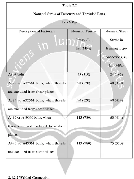
Table 2.2
Nominal Stress of Fasteners and Threaded Parts, ksi (MPa)
Description of Fasteners Nominal Tensile Stress, Fnt ,
ksi (MPa)
Nominal Shear Stress in Bearing-Type Connections, Fnv,
ksi (MPa)
A307 bolts 45 (310) 24 (165)
A325 or A325M bolts, when threads are excluded from shear planes
90 (620) 48 (330)
A325 or A325M bolts, when threads are excluded from shear planes
90 (620) 60 (414)
A490 or A490M bolts, when
threads are not excluded from shear planes
113 (780) 60 (414)
A490 or A490M bolts, when threads are excluded from shear planes
113 (780) 75 (520)
2.4.2.2 Welded Connection
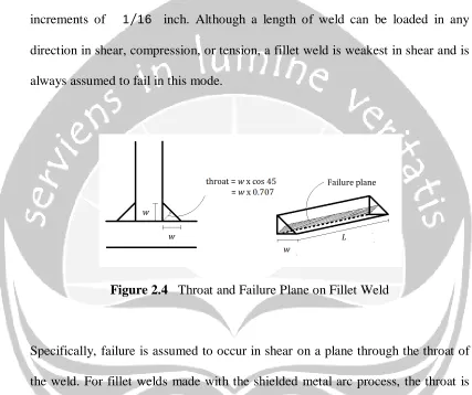
reinforcement (buildup outside the hypotenuse of the triangle) or penetration is neglected. The size of a fillet weld is denoted w and is the length of one of the two equal sides of this idealized cross section. Standard weld sizes are specified in increments of 1 16⁄ inch. Although a length of weld can be loaded in any direction in shear, compression, or tension, a fillet weld is weakest in shear and is always assumed to fail in this mode.
Figure 2.4 Throat and Failure Plane on Fillet Weld
Specifically, failure is assumed to occur in shear on a plane through the throat of the weld. For fillet welds made with the shielded metal arc process, the throat is the perpendicular distance from the corner, or root, of the weld to the hypotenuse and is equal to 0.707 times the size of the weld. Thus, for a given length of weld L subjected to a load P, the critical shearing stress is
fv =
If the weld ultimate shearing stress, Fw, is used in this equation, the nominal load capacity of the weld can be written as
Rn = 0.707 w L Fw And the nominal design strength is,
Rn = (0.707 w L Fw)
where = 0.75
The strength of fillet weld depends on the weld metal used, it is a function of the type of electrode. The strength of electrode is defined as its ultimate tensile strength. The standard notation for specifying an eletrode is the letter E followed by two or three digits indicating the tensile strength in Kips per square inch and two digits specifying the type of coating. As strength is the property of primary concern to the design engineer, the last two digits are usually represented by XX, and a typical designation would be E70XX or just E70, indicating an electrode with an ultimate tensile strength of 70 Ksi.
The ultimate shearing stress Fw in a fillet weld is 0.6 times the tensile strength of the weld metal, denoted FEXX. The nominal stress is therefore
Fw = 0.60 FEXX
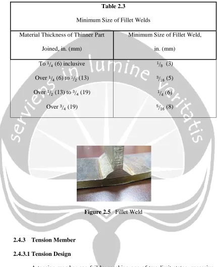
Table 2.3
Minimum Size of Fillet Welds Material Thickness of Thinner Part
Joined, in. (mm)
Minimum Size of Fillet Weld, in. (mm)
To 1
4 (6) inclusive
Over 1
4 (6) to 12 (13)
Over 1
2 (13) to 34 (19)
Over 3
4 (19)
1 8 (3) 3
16 (5) 1
4 (6) 5
16 (8)
Figure 2.5 Fillet Weld
2.4.3 Tension Member
2.4.3.1 Tension Design
section must be less than the tensile strength Fu. In each case, the stress P/A must be less than a limiting stress F or
< F
Thus the load P must be less than F A, or P < F A
The left side of this expression is the applied factored load, amd the right side is the strength. The nominal strength in yielding is,
Pn = Fy Ag And the nominal strength in fracture is,
Pn = Fu Ae
Where Ae is the effective net area, which may be equal to either the net area or, in some cases, a smaller area.
The resistance factor = t is smaller for fracture than for yielding, reflectiong the more serious nature of reaching the limit states of fracture.
For yielding, t = 0.90 For fracture, t = 0.75
So from explation above it can be write as, Pu≤ t Rn
or
Pu≤ t Pn
Pu≤ 0.90 Fy Ag Pu≤ 0.75 Fu Ae
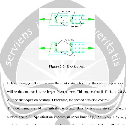
2.4.3.2 Block Shear
For certain connection configuration a segment or “block” of material at the end of the member can tear out. For example, the connection of a plate tension member shown in Figure 2.3 is susceptible to this phenomenon, called block shear. For the case ilustrated, the shaded block would tend to fail by shear along the longitudinal section and by tension on the transverse section.
The procedure is based on the assumption that one of two failure surfaces fractures and the other yields. That is, fracture on shear surface isaccompanied by yielding on the tension surface, or fracture on the tension surface accompanies yielding on the shear surface. Both surfaces contribute to the total strength, and the resistance to block shear will be the sum of the strengths of two surfaces. The nominal strength in tension is Fu Ant for fracture and Fy Agt for yielding, where Ant and Agt are the net and gross areas along the tension surface. Taking the shear yield stress and ultimate stress as 60% of the values for tension, the nominal strength for shear fracture is 0.6 Fu Anv, and the strength for shear yielding is 0.6 Fy Agv, where Anv and Agv are the net and gross areas along the shear surface. There are two failure modes. For shear yield and tension fracture, the design strength is
Rn = [ 0.6 Fy Agv + Fu Ant ]
Rn = [ 0.6 Fu Anv + Fy Agt ]
Figure 2.6 Block Shear
In both cases, = 0.75. Because the limit state is fracture, the controlling equation will be the one that has the larger fracture term. This means that if Fu Ant > 0.6 Fu Anv, the first equation controls. Otherwise, the second equation control.
To avoid using a yield strength that is greater than the fracture strength along a surface, the AISC Spesification imposes an upper limit of [ 0.6 Fu Anv + Fu Ant ] on both equations. For some types of connection , block shear failure will actually involve fracture along both the shear and tension surfaces ( Birkemoe and Gilmor, 1978 ). The block shear strength is therefore given in AISC J4.3 as follows:
a. When Fu Ant≥ 0.6 Fu Anv
Rn = [ 0.6 Fy Agv + Fu Ant ] ≤ [ 0.6 Fu Anv + Fu Ant ]
Rn = [ 0.6 Fu Anv + Fy Agt ] ≤ [ 0.6 Fu Anv + Fu Ant ]
2.4.4 Compression Member 2.4.4.1 Compresion Design
The requirement for compression members are covered in Chapter E of the AISC Spesification. The relationship between loads and strength takes the form
Pu ≤ c Pn where:
Pu = sum of factored loads
Pn = nominal compressive strength = Ag Fcr Fcr = critical buckling stress
c = resistance factor for compression member = 0.85
Instead of expressing the critical buckling stress Fcr as a function of the slenderness ratio , the pesification uses the slenderness parameter
λc =
which incorporates the material properties but is nondimensional. For elasic members, it can written as
Fcr = ( ⁄ )
=
For inelastic members, the tangent modulus equation is written as Fcr = ( 0.658
Thus a direct a direct solution can be obtained, avoiding the trial and error approach inherent in the use of the tangent modulus equation. If the boundary between elastic and inelastic members is taken as λc = 1.5, the AISC equation for critical buckling stress can be summarized as follows.
For λc ≤ 1.5 , Fcr = ( 0.658
) Fy For λc ≥ 1.5 ,
Fcr = 0.877 2
2.5 Gusset Plate
The primary design steps for a gusset-plate connection, which take these failure modes into consideration, are as follows.
• The welds or bolts used to attach the brace to the gusset plate must be designed to provide the expected tensile yield resistance of the brace, and the weld length or bolt group must also be checked using the block shear design expression.
• The welds, which are fillet or complete joint penetration (CJP) welds, attaching the gusset plate to the beam and column are sized (the interface welds) for design forces determined using equilibrium methods with the expected tensile force in the brace.
Figure 2.7 Schematic of SCBF gusset plate connections and design checks
(a) welded tube brace; (b) bolted angle connection; (c) gusset plate welds; and (d) free edge buckling