UNIVERSITI TEKNIKAL MALAYSIA MELAKA
INVESTIGATION ON THE EFFECT OF MACHINING
STRATEGIES ON THE SURFACE FINISH AND DIMENSIONAL
ACCURACY OF FIVE-AXIS FLANK MACHINING OF CURVY
ANGLED SHAPES (CONVEX)
This report submitted in accordance with requirement of the Universiti Teknikal Malaysia Melaka (UTeM) for the Bachelor Degree of Engineering Technology
(Process and Technology) (Hons.)
by
AHMAD SYAZILI BIN MD DIN B071210454
900812-02-6139
UNIVERSITI TEKNIKAL MALAYSIA MELAKA
BORANG PENGESAHAN STATUS LAPORAN PROJEK SARJANA MUDA
TAJUK: INVESTIGATION ON THE EFFECT OF MACHINING STRATEGIES ON
THE SURFACE FINISH AND DIMENSIONAL ACCURACY OF FIVE-AXIS FLANK MACHINING OF CURVY ANGLED SHAPES (CONVEX)
SESI PENGAJIAN: 2014/15 Semester 1
Saya AHMAD SYAZILI BIN MD DIN
mengaku membenarkan Laporan PSM ini disimpan di Perpustakaan Universiti Teknikal Malaysia Melaka (UTeM) dengan syarat-syarat kegunaan seperti berikut:
1. Laporan PSM adalah hak milik Universiti Teknikal Malaysia Melaka dan penulis. 2. Perpustakaan Universiti Teknikal Malaysia Melaka dibenarkan membuat salinan
untuk tujuan pengajian sahaja dengan izin penulis.
3. Perpustakaan dibenarkan membuat salinan laporan PSM ini sebagai bahan pertukaran antara institusi pengajian tinggi.
4. **Sila tandakan ( )
SULIT
TERHAD
TIDAK TERHAD
(Mengandungi maklumat yang berdarjah keselamatan atau kepentingan Malaysia sebagaimana yang termaktub dalam AKTA RAHSIA RASMI 1972)
(Mengandungi maklumat TERHAD yang telah ditentukan oleh organisasi/badan di mana penyelidikan dijalankan)
Alamat Tetap:
DECLARATION
I hereby, declared this report entitled “Investigation on the Effect of Machining Strategies on the Surface Finish and Dimensional Accuracy of Five-Axis Flank Machining of Curvy Angled Shapes (Convex)” is the results of my own research
except as cited in references.
Signature :………
Name : ………
v
APPROVAL
This report is submitted to the Faculty of Engineering Technology of UTeM as a partial fulfillment of the requirements for the degree of Bachelor of Engineering Technology (Process and Technology) (Hons.). The member of the supervisory is as follow:
vi
ABSTRACT
vii
ABSTRAK
viii
DEDICATIONS
ix
ACKNOWLEDGMENTS
In the name of Allah, the Compassionate, the Merciful, Praise be to Allah, Lord of the Universe, and Peace and Prayers be upon His Prophet and Messenger. With Grace and Blessing from Allah, I am Ahmad Syazili Bin Md Din from Faculty of Engineering Technology have succeeded in completing my final year project together with this thesis. First and foremost, I would like thank to Allah, because of His willing and Blessing, I have succeeded in completing this project. High appreciate to my supportive project supervisor, En. Syahrul Azwan Bin Sundi @ Suandi for his guidance during performing this project.
Special thanks to everybody who help me to accomplish this project. For all helpful lecturers and technician, thank for supporting me everything regarding this project, teaching me some new and valuable knowledge and providing me with great equipment while conducting this experiment.
x
TABLE OF CONTENTS
DECLARATION ... iv
APPROVAL ... v
ABSTRACT ... vi
ABSTRAK ... vii
DEDICATIONS ... viii
ACKNOWLEDGMENTS ... ix
TABLE OF CONTENTS ... x
LIST OF FIGURES ... xv
LIST OF TABLE ... xvii
LIST OF SYMBOLS AND ABBREVIATIONS ... xviii
CHAPTER 1 ... 1
1.0 Introduction ... 1
1.1 Problem Statement ... 5
1.2 Objectives ... 5
1.3 Scope of Study ... 6
CHAPTER 2 ... 7
2.0 Introduction ... 7
2.1 Five-axis Machining ... 7
2.2 Machining Strategies ... 9
xi
2.2.3 Combin Parelm ... 11
2.3 Flank Machining ... 12
2.4 Dimensional Accuracy ... 14
2.5 Surface Finish ... 15
2.6 Convex Angle Surface ... 17
2.7 Aluminum Alloy 6063 ... 18
2.8 Best Fit Curve Measurement ... 20
CHAPTER 3 ... 21
3.0 Introduction ... 21
3.1 Project Planning ... 21
3.1.1 Phase 1 ... 23
3.1.2 Phase 2 ... 23
3.2 Computer Aided Design (CAD) ... 24
3.3 Computer Aided Manufacturing (CAM) ... 26
3.3.1 Define Machine ... 29
3.3.2 Define Axis ... 30
3.3.3 Define Product ... 30
3.3.4 Define Part ... 31
3.3.5 Define Stock ... 31
3.3.6 Define Tool ... 31
3.3.7 Manufacturing program ... 32
xii
3.3.9 Roughing operation ... 33
3.3.10 Pocketing ... 34
3.3.11 Multi-axis Flank Contouring ... 35
3.3.11.1 Tanto Fan ... 35
3.3.11.2 Combin Tanto ... 36
3.3.11.3 Combin Parelm ... 37
3.3.12 Post Processor ... 37
3.4 Machining ... 38
3.5 Measurement ... 40
3.5.1 Coordinate Measuring Machine (Carl Zeiss Contura G2 RDS) ... 40
3.5.1.1 Curve measurement ... 41
3.5.2 Surface Roughness Measuring Tester (Mitutoyo Sj-410) ... 42
3.5.2.1 Surface roughness measurement ... 43
CHAPTER 4 ... 45
4.0 Introduction ... 45
4.1 Dimensional accuracy Result ... 45
4.2 Surface roughness result ... 49
4.3 Comparison on dimensional accuracy analysis ... 51
4.3.1 Comparison dimensional accuracy at point A ... 51
4.3.2 Comparison dimensional accuracy at point B ... 52
4.3.3 Comparison dimensional accuracy at point C ... 53
xiii
Combin Tanto ... 56
4.3.6 Comparison dimensional accuracy at point A, point B and point C of Combin Parelm ... 57
4.4 Comparison on surface roughness analysis ... 59
4.4.1 Comparison surface roughness at point A ... 59
4.4.2 Comparison surface roughness at point B ... 60
4.4.3 Comparison surface roughness at point C ... 61
4.4.4 Comparison surface roughness at point A, point B and point C of Tanto Fan 62 4.4.5 Comparison surface roughness at point A, point B and point C of Combin Tanto ... 64
4.4.6 Comparison surface roughness at point A, point B and point C of Combin Parelm ... 66
4.5 Dimensional accuracy analysis of machining strategies ... 68
4.6 Surface roughness analysis of machining strategies ... 70
4.7 Tool wear ... 72
4.8 Post processor of CNC ... 72
CHAPTER 5 ... 73
5.0 Introduction ... 73
5.1 Dimensional analysis conclusion ... 73
5.2 Surface roughness conclusion ... 74
5.3 Future work ... 74
xiv
xv
Figure 1.1: Mechanism of cutting tool in flank contouring. ... 3
Figure 1.2: : Surface finish characteristics. ... 4
Figure 1.3: Differences between Concave and Convex curve shape ... 4
Figure 2.1: Five side machining process. ... 8
Figure 2.2: : The cutting tool clearly shown that the tool is tangent to the drive surface at a given contact height and tool axis is the interpolation between the start and end positions. ... 10
Figure 2.3: The cutting tool clearly shown that the tool is tangent to the drive surface at a given contact height and the tool axis contained in a plane normal to forward direction... 11
Figure 2.4: The cutting tool clearly shown that the tool axis is tangent to the drive surface at the specified contact height and follows the isoparametrics of the surface. ... 12
Figure 2.5: Differences between Multi-axis Flank Contouring and Flank Contouring. ... 12
Figure 2.6: Graph of ‘Ra’. ... 15
Figure 2.7: Graph of ‘Ry’... 15
Figure 2.8: Graph of ‘Rz’. ... 16
Figure 2.9: Example of convex angle surface machining in multi-axis flank contouring offered by CATIA V5. ... 17
Figure 2.10: Example of convex angle surface machining in multi-axis flank contouring offered by CATIA V5. ... 20
Figure 3.1: Flow Chart Methodology ... 22
Figure 3.2: Flow Chart of CAD process ... 24
Figure 3.3: Location of WPC ... 25
Figure 3.4: Flow Chart of CAM process ... 28
Figure 3.5: Select machine type ... 29
Figure 3.6: Selected of Reference Axis... 30
Figure 3.7: Selected of product ... 30
Figure 3.8: Selected of Part ... 31
Figure 3.9: Selected of Stock ... 31
Figure 3.10: Selected of tool ... 32
Figure 3.11:List of Manufacturing Program ... 32
Figure 3.12: Cutting tool path simultion for facing ... 33
Figure 3.13: Cutting tool path simultion for roughing ... 34
Figure 3.14: Cutting tool path simultion for pocketing ... 34
Figure 3.15: Cutting tool path simultion for multi-axis flank contouring ... 35
Figure 3.16: Tool axis simulation of Tanto Fan ... 36
Figure 3.17: Tool axis simulation of Combin Tanto ... 36
xvi
Figure 3.19: Flow chart of post processor ... 37
Figure 3.20: Deckel Maho DMU 60 Monoblock ... 39
Figure 3.21: Multi-axis flank contouring machining process ... 40
Figure 3.22: Zeiss Coordinate Measuring Machine ... 40
Figure 3.23: The location of base alignment on sample ... 42
Figure 3.24: The probing process for the sample. ... 42
Figure 3.25: Roughness tester Mitutoyo SJ-410. ... 43
Figure 3.26: . Detector stylus was parallel to the measured surface ... 44
Figure 3.27:Examples of surface roughness reading. ... 44
Figure 4.1: Point taken for the dimensional analysis on the machining flank. ... 46
Figure 4.2: Start and end point of the probing process. ... 46
Figure 4.3: CMM Measurement result of Tanto Fan at position A. ... 47
Figure 4.4: CMM Measurement result of Combin Tanto at position A... 47
Figure 4.5: CMM Measurement result of Combin Parelm at position A... 47
Figure 4.6: Point taken for the Surface roughness analysis on the machining flank. 49 Figure 4.7: Chart of dimensional accuracy at point A ... 51
Figure 4.8: Chart of dimensional accuracy at point B. ... 52
Figure 4.9: Chart of dimensional accuracy at point C ... 53
Figure 4.10: Chart of dimensional accuracy at point A, point B and point C of Tanto Fan ... 54
Figure 4.11: Chart of the Mean of sigma value at all point for Tanto Fan ... 55
Figure 4.12: Chart of dimensional accuracy at point A, point B and point C of Combin Tanto ... 56
Figure 4.13: Chart of the Mean of sigma value at all point for Combin Tanto ... 57
Figure 4.14: Chart of dimensional accuracy at point A, point B and point C of Combin Parelm ... 58
Figure 4.15: Chart of the Mean of sigma value at all point for Combin Parelm ... 58
Figure 4.16: Chart of surface roughness at point A ... 60
Figure 4.17: Chart of surface roughness at point B ... 61
Figure 4.18: Chart of surface roughness at point C ... 62
Figure 4.19: Chart of surface roughness at point A, point B and point C of Tanto Fan ... 63
Figure 4.20: Chart of the mean ‘Ra’ value at all point for Tanto Fan... 64
Figure 4.21: Chart of surface roughness at point A, point B and point C of Combin Tanto ... 65
Figure 4.22: Chart of the mean ‘Ra’ value at all point for Combin Tanto ... 65
Figure 4.23: Chart of surface roughness at point A, point B and point C of Combin Parelm ... 66
Figure 4.24: Chart of the mean ‘Ra’ value at all point for Combin Parelm ... 67
Figure 4.25: Chart of mean sigma value at all points in all machining strategies ... 68
xvii
Table 2.1: Comparison between composition of aluminium alloy 6000 series and
7000 series. ... 18
Table 3.1: Deckel Maho DMU 60 Monoblock specifications. ... 38
Table 3.2: Zeiss Coordinate Measuring Machine specifications ... 41
Table 4.1: Actual measurement result of Tanto Fan at all position. ... 48
Table 4.2: Actual measurement result of Combin Tanto at all position ... 48
Table 4.3: Actual measurement result of Combin Parelm at all position. ... 48
Table 4.4: Actual surface roughness result of Tanto Fan at all position ... 49
Table 4.5: Actual surface roughness result of Combin Tanto at all position. ... 50
Table 4.6: Actual surface roughness result of Combin Parelm at all position. ... 50
Table 4.7: Ranking of the best machining strategies by dimensional accuracy ... 68
xviii
LIST OF SYMBOLS AND ABBREVIATIONS
CAD = Computer Aided Design
CAM = Computer Aided Manufacturing CNC = Computer Numerical Control CMM = Coordinate Measuring Machine WPC = Work piece Coordinate
1
CHAPTER 1
INTRODUCTION
1.0 Introduction
The purpose of this research is to investigate the effect of machining strategies that are offered by CATIA V5 as the CAD/CAM software which will be used. Tanto Fan, Combin Tanto, and Combin Parallelism are the strategies that going to be applied. Each option of machining strategy used is expected to give different results of machining process in term of surface finish and dimensional accuracy. In addition, this research also emphasize to actual part because of the typical problem that the industry faced is necessary to do several test cutting in order to release a product that satisfy the customer specifications.
5-axis CNC machining has been commonly used in manufacturing of complex geometries in automobile, aerospace, energy, and mould industries. This advanced machining operation provides better shaping capability and higher productivity compared to traditional 3-axis machining. 5-axis machining provides infinite possibilities as to the part sizes and shapes can effectively process. The term “5-axis” refers to the number of directions in which the cutting tool can move. On a 5-axis machining centre, the cutting tool moves across the X, Y and Z linear axes as well as rotates on the A and B axis to approach the workpiece from any direction. In other words, five sides of a part can be processed in a single setup. Nevertheless, manufacturing of complex workpieces is still difficult, although the 5-axis machining proposes a lot of new possibilities and advantages (López, 2005). In addition, the geometrical accuracy of 5-axis machine tools is also an important factor.
2
At the same time, many of these strategies can improve the productivity of older CNC machines with dramatically reduced air cutting time and programs with smooth arcs which help to maintain continuous machine tool motion. Machining strategist can take the machining capabilities to new levels and productivity to new heights. Machining strategist has been developed to be very easy to learn and use. Machining strategist includes, Z-level Roughing, Horizontal Finish Machining, Fixed axis and few other strategist.
3
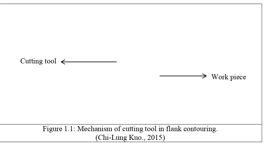
Figure 1.1: Mechanism of cutting tool in flank contouring. (Chi-Lung Kuo., 2015)
The finish machining work piece will undergo the dimensional and surface finish analysis process. Two types of accuracy in manufacturing can be distinguished which is dimensional accuracy and shape accuracy. Dimensional accuracy is achieved when the final product falls within the tolerance bands for each dimension specified on the drawings. Increasing demand for performance designs todays, aerospace components having complex geometries and surfaces are required to be manufactured in tight tolerances. Thus, in this research the products will be undergoing the dimensional accuracy test by using a CMM machine. The testing will be done by comparing the dimensional accuracy between Combin Tanto, Tanto Fan, and Combin Parelm sample.
Surface finish or also known as surface texture or surface topography is the nature of a surface as defined by the 3 characteristic which is surface roughness, waviness and lay. Surface roughness commonly shortened to roughness, is a measure of the finely spaced surface irregularities. In engineering, this is what is usually meant by "surface finish". Meanwhile, lay is the direction of the predominant surface pattern ordinarily determined by the production method used. Lastly, waviness is the measure of surface irregularities with spacing greater than that of surface roughness. These usually occur due to warping, vibrations, or deflection during machining.
Cutting tool
4
Figure 1.2: : Surface finish characteristics. T.V, V. (1990)
There are two classes of polygons, which is convex and concave. In a convex polygon, no diagonal goes outside the figure as it travels from one corner to the other. Another property of convex polygons is that no angle inside the polygon will have a measure greater than 180 degrees. Meanwhile, Concave curve describes and inward curve while convex curve in opposites means a curve that bulges outward. They are used to describe gentle, subtle curves like the kinds found in mirrors or lenses. In mathematics, a convex function is the positive of a concave function. A convex function is also synonymously called convex downward, convex down, concave upwards, concave cap or upper concave.
5
Nowadays, products designed in aerospace industries are becoming more and more complex and complicated to meet the increasing demand of customers. Due to strong requirement from this industry, this research is utilized 5-Axis machining which offers several advantages over the traditional 3-axis machining in producing complex shape surfaces, reduces the machining time and improves the surface finish.
Most work so far has focused on point milling with end-milling of doubly curved surfaces. While much attention has been focused on machining with the bottom end of cutters (D. Dragomatz, 1997), less research has been done on a flank milling, which can provide large productivity gains for such class of surfaces as are found in blades, fans, turbines and other engineering objects (J.-M. Redonnet, 1998). Rather than milling with the tip of the tool, flank milling cuts with the shaft of the tool, removing greater amounts of material in a single pass. Flank milling is useful for machining objects such as impellers, blisks, and turbine blades, where accuracy is important. With flank milling the surface can be cut with a single pass, which is more efficient than point milling methods.
Next, common industry needs to do several test cuts in order to produce good finished product. The reason is the industry need to determine the best parameters such as tool axis for flank milling. The tool axis option named Combin Tanto, Tanto Fan, and Combin Parelm has a small contrast between each other. This small contrast between tool axis confusing the programmer to match the flank shape with the tool axis options. Moreover, this will lead to high production cost and take several times. Therefore, it is essential to study on machining strategies for flank contouring in order to know exactly the most suitable strategy for flank contouring parts.
1.2 Objectives
6
(a) To investigate the effect on surface finish and dimensional accuracy based on machining strategies.
(b) To study the surface machining strategies (Tanto Fan, Combined Tanto, and Combined Parallelism) in producing flank shape.
(c) To make recommendations on the best machining strategy for flank at convex curve shape.
1.3 Scope of Study
7
CHAPTER 2
LITERATURE REVIEW
2.0 Introduction
Literature review discussed the relevant topics and a guide for studies. This section will give part in order to get more information about machining strategies of multi-axis flank contouring and will give idea how the flank machining worked. At an early stage of the studies, some gap analysis has been carried out in order to ensure the relevance of this research. Reference books, research journals and online conference article were the main source in the thesis guides. This section will include the principle of 5-axis machining, flank machining, machining strategies, dimensional accuracy, surface finish, convex angle shape and Aluminum 6063.
2.1 Five-axis Machining