UNIVERSITI TEKNIKAL MALAYSIA MELAKA
VALIDATION AND IMPROVEMENT OF 14-DOF RIDE AND
HANDLING MODEL FOR PASSENGER VEHICLE
This report submitted in accordance with requirement of the Universiti Teknikal Malaysia Melaka (UTeM) for the Bachelor’s Degree in Mechanical Engineering
Technology (Automotive Technology) (Hons.)
by
RUZAIDI BIN RAZALI B071110421 921125-11-6151
UNIVERSITI TEKNIKAL MALAYSIA MELAKA
BORANG PENGESAHAN STATUS LAPORAN PROJEK SARJANA MUDA
TAJUK: Validation and Improvement of 14-DOF Ride and Handling Model for Passenger Vehicle
SESI PENGAJIAN: 2014/15 Semester 2
Saya RUZAIDI BIN RAZALI
mengaku membenarkan Laporan PSM ini disimpan di Perpustakaan Universiti Teknikal Malaysia Melaka (UTeM) dengan syarat-syarat kegunaan seperti berikut: 1. Laporan PSM adalah hak milik Universiti Teknikal Malaysia Melaka dan penulis. 2. Perpustakaan Universiti Teknikal Malaysia Melaka dibenarkan membuat salinan
untuk tujuan pengajian sahaja dengan izin penulis.
3. Perpustakaan dibenarkan membuat salinan laporan PSM ini sebagai bahan pertukaran antara institusi pengajian tinggi.
4. **Sila tandakan ( )
SULIT
TERHAD
TIDAK TERHAD
(Mengandungi maklumat yang berdarjah keselamatan atau kepentingan Malaysia sebagaimana yang termaktub dalam AKTA RAHSIA RASMI 1972)
(Mengandungi maklumat TERHAD yang telah ditentukan oleh organisasi/badan di mana penyelidikan dijalankan)
Alamat Tetap:
iii
DECLARATION
I hereby, declared this report entitled “Validation and Improvement of 14-DOF Ride and Handling Model for Passenger Vehicle” is the results of my own research
except as cited in references.
Signature : ……….
Author’s Name : ………
iv
APPROVAL
This report is submitted to the Faculty of Engineering Technology of UTeM as a partial fulfillment of the requirements for the degree of Bachelor of Mechanical Engineering Technology (Automotive Technology) (Hons.). The member of the supervisory is as follow:
………
v
ABSTRAK
vi
ABSTRACT
There are many vehicle models that have been developed for the study of the vehicle dynamics specifically for the ride and handling behavior. This thesis describes the development of vehicle model to study the behavior of the vehicle after improvement with semi-active suspension system. The derivation of a 14 DOF vehicle model consists of ride, handling and tire model are presented. The most accurate combination of controller and actuator which follows the comparing result of the MATLAB with CARSIM software was chosen to be coupled with the 14 DOF model. All the assumptions made for the 14 DOF with semi-active system vehicle model is stated. The 14 DOF vehicle model will then be validate using CARSIM software. The results discuss suc as yaw rate, lateral acceleration and roll angle of the vehicle body and also the slip angle at each tire.
vii
DEDICATION
Dedicated to my supportive mother, Mrs. Rubiah binti Ab. Rashid. To my supervisor, Engr. Nur Rashid bin Mat Nuri@Md Din, co-supervisor, Engr. Mohamad
viii
ACKNOWLEDGEMENT
Alhamdullilah, I am grateful to ALLAH S.W.T. on blessing me in completing this project.
I wish to express my sincere appreciation to honourable Associate Engr. Nur Rashid bin Mat Nuri@Md Din my supervisor of this project. Thank you for the encouragement, guidance and critics. Without his continued support, idea and knowledge received, this thesis would not possible to complete.
I am also indebted to University Teknikal Malaysia Melaka (UTeM) and PTPTN for funding my study.
ix
2.3 Semi-active Control Strategies 11
x
3.2.2 Ride model 22
3.2.3 Tire model 25
3.2.4 Summary 14 DOF vehicle model 26
3.3 Controller Model 26
3.4 Actuator Model 29
3.5 Full Vehicle Simulink Model 33
CHAPTER 4: RESULT & DISCUSSION 36
4.1 Simulation and Validation 36
4.1.1 Ride model validation 37
4.1.2 Handling model validation 42
4.2 Improvement of Suspension Model 48
CHAPTER 5: CONCLUSION AND RECOMMENDATION 55
REFERENCES 56
APPENDICES
xi
LIST OF TABLES
2.1 The Ranking Of The Different Active Suspension System Used For Agricultural Tractors (Shahriarsarami, 2009)
11
3.1 3.2 3.3 3.4
Quarter- Car Suspension Model Parameter Parameters For Handling Equation
Parameters For Ride Equation
Illustration Of The Working Of On-Off Skyhook Control Strategy
19 22 24 28
4.1 Vehicle Ride Model Parameter 37
4.2 Vehicle Handling Model Parameter 43
4.3 Tire parameter 43
4.4 Effect Of Stiffness And Damping Coefficent On Body Acceleration
51
4.5 Effect Of Stiffness And Damping Coefficent On Body Acceleration
xii
Fully Active Suspension Model
Configuration Of A Low-Bandwidth Active Suspension (Williams, 1994)
Working Area Of The Semi-Active And Fully Active Suspensions (Shahriarsarami, 2009)
Hydro-Pneumatic Suspension With Controllable Throttle (Shahriarsarami, 2009)
Schematic Illustration Of A Mr Damper (Paré, 1998) Skyhook Damper Force With Quarter Car Model Ground-Hook Damping Approach
Control Loop In A Vehicle With Semi-Active Suspension System.
Modelling Procedure
Quarter-Car Model And Relevant Free Body Diagram 3-Dof Handling Vehicle Model
7-Dof Ride Vehicles Model Nonlinear Black Box Tire Model Relationship For Each Model Skyhook Model
Mr Fluid Particles Behavior
Schematic Configuration Of Mr Damper Full Vehicles Simulink Model
Skyhook On-Off Controller
The Damper In Simulink Model For Front Suspension
17
4.1 Vehicle Ride Model in Simulink 37
xiii
4.3 Animation Of Large Smooth Bump 39
4.4 Body Acceleration vs Time For CARSIM 40
4.5 Body Acceleration vs Time For MATLAB 41
4.6 Vehicle Handling Model in Simulink 42
4.7 CARSIM Command Window For Simulate Vehicle Handling Test
Animation Of Double Lane Change (DLC @ 120km/H)
Lateral Acceleration Computed From MATLAB Simulink And CARSIM
Yaw Angle Computed From MATLAB Simulink And CARSIM Roll Angle Computed From MATLAB Simulink And CARSIM Pitch Angle Computed From MATLAB Simulink And CARSIM Block Parameter For Spring Stiffness And Suspension Damping Body Acceleration Vs Time (Ks=55000,Cs=1000,
Cs=2500,Cs=4000)
Body Acceleration Vs Time (Cs=3000, Ks=10000,Ks=25000, Ks=40000)
Graph Of Improvement vs previous results
xiv
LIST OF ABBREVIATIONS, SYMBOLS AND
NOMENCLATURE
DOF - Degree of Freedom RLF - Radlastfactor
MR - Magneto-rheological ER - Electro-rheological
- Yaw Angular Acceleration - Longitudinal axis acceleration - Lateral axis acceleration
L - Wheelbase
- Vertical axis moment of inertia
- Pitch angular acceleration - Roll axis angular acceleration
1
1.1 Background of the Study
This paper studies technology for a thesis of vehicle dynamics model based on selected parameter model to simulate driving characteristics vehicle control precisely. The purpose for road vehicle suspension design is to find a satisfying tolerance solution that can provide enough control of ride vibration, roll and pitch motions due to different motion and external excitations. Besides, the rotational motions together with the road roughness induced translational motions extremely influence the ride comfort, the load transfer affect tire force, cornering and braking forces. These changes directly influence the direction, braking dynamic responses and stability limits of road vehicles in a dynamic condition. Under various road surface and steering or braking movement, a full vehicle dynamic model is developed with semi-active system and validates to improve vehicle ride and handling dynamic response, suspension anti-roll and anti-pitch characteristics. MATLAB (Simulink) based on 14 DOF full vehicle model consists of ride vehicle model, handling vehicle model and tire model were constructed. 14 DOF result will compare with CARSIM to verify the best model at the end of this research.
INTRODUCTION
2
1.2 Problem Statement
The problem statement is much suspension system that used linear model with decrease the number of degree of freedom (DOF). A quarter car models are very commonly used. Although this is basic model, it is important in vehicle dynamic for equilibrium analysis. These simple models do not give accurate result in suspension geometry calculation, except for the motion ratio. This leads to model inaccuracies when models are used to simulate vehicle behavior with extreme wheel travel typical off-road driving. Simplified models are also considered inaccurate when to study
about transient’s behavior. So the reason to use high number of DOF with the lumped mass model is that it is linear and the physical significance of variables is easy to study. With more complex models, the connection between real physical quantities and variables disappear easily. A quarter car models cannot demands with high multi objectives. Besides, the wide use of vehicles as an example for the theories of modern control technology, there are many different solutions for the vehicle suspension problem. The solutions obtained with this type of models can be adjustable with correct controller and actuator. Most of these solutions are virtually impossible to apply on real world vehicle but it is still keep going to find the possible solution for the improvement of car suspension.
1.3 Objective
(i) To validate the MATLAB Simulink results with CARSIM software
3
1.4 Scope
There are three parts for this study. First part is about 14-DOF model. It is represented by:
(i) Handling vehicle model (3-DOF). It is consist of longitudinal translation, lateral translation, and rotation of vehicle mass center.
(ii) Ride vehicle model (7-DOF). This model has 3-DOF of mass center (Vertical, roll, pitch dynamic) and 4-DOF of each wheel (wheel vertical dynamic).
(iii) Tire model (4-DOF). It is consist of longitudinal 1-DOF of each tire.
For the second part, suspension system with variable parameter value of spring stiffness and damping suspension were chosen as a method to improve the suspension model. This method should control damper and suspension spring by using controller damper that can decrease the resonant peak of the body mass and give a good quality handling.
4 In this chapter the literature review is presented. It will discuss about general definition about vehicle suspension, different types of suspension model and control strategies for semi-active suspension.
2.1 Vehicle Suspension
Ride comfort is an important factor of the suspension system of vehicles. It is represented how much the vehicle give comfortable to the passenger. Ride comfort is very important for agricultural tractors, because the acceleration transmitting to the driver compared with other vehicles is very high (Horton&Crolla, 1984). Agricultural tractors same like passenger vehicle driver, the driver needs comfortable especially when travelling on the long distance. These conditions can affect the comfort, efficiency, alertness, and health of the driver.
Vibration sources that affect ride comfort are categorized generally into two classes, namely on-board sources and road sources (Jamei, 2002). The components have the wheels, the driveline, and the engine arise on-board sources from the rotating. These sources caused aural vibrations in the frequency region of 25 - 20,000 Hz, which are called "noise" (Gillespie, 1992).These two frequencies are the lower and higher frequency thresholds of human hearing. The road sources are the second category of the vibration sources of the vehicles, referring to the road roughness and maneuver excitations. Normally frequency range of these excitations is 0-25 Hz. This range frequency is natural frequency that most sensitive to human body area. So, the
LITERATURE REVIEW
5 most important factor in affecting ride comfort of a vehicle is road excitation sources.
Stable and safe driving car can be created with considered handling characteristics to make sure the contact between the tires and road surface.
(Mitschke, 1984) defined a factor called RLF “Radlastfaktor” in order to quantify
vehicle handling. For calculation, addition the vertical dynamic tire force with considering vertical static tire forces. RLF factor is equal to the value of the dynamic tire force over the value of the static tire force. The higher of this factor the higher instability in the tire contact. With RLF factor, handling of vehicles can be examines. This factor was also used by (Hoppe, 2006) in order to evaluate the handling capability of a full suspension tractor
2.2 Types of Suspension
There are two types of suspension will be discussed on this section. There are many types of suspension have been created in order to study about vehicle behavior. But these two suspensions are commonly used. So, the comparisons between them were made to choose the best one.
2.2.1 Fully active suspension system
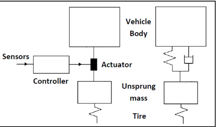
6 Figure 2.1: Fully active suspension model
This suspension model created to control over the full bandwidth of suspension system. The suspension response the natural frequencies of the vehicle body and wheels. These natural frequencies of typical vehicles are 1-3 Hz of the vehicle body and 5-15 Hz of the wheels (Williams, 1994). These systems cover the full bandwidth of the suspension system and are able to perform a complete control on the vibrations. This provides good ride comfort and road stability for vehicle. However, the high bandwidth control leads to a significant quantity of power consumption, which is approximately until 10 kW for the normal automobiles. This high power consumption can affect negatively the overall performance of the vehicle and increases the fuel consumption in the range of 10 – 15 % (Williams, 1994).
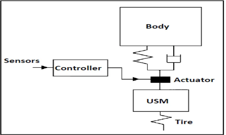
7 Although fully active system has many advantages but it also has their weakness. Normally, this system just used for luxury or special vehicles. So, in order to increase performance of this system, low-bandwidth type of these systems is created. In this new system, the actuator is arranged in series with a passive spring and passive damper. The more detailed about the low band-width fully active suspension model is represented on the Figure 2.2. On the contrary, the goals to improve the suspension response just around the natural frequencies of the body vehicle, with the typical range of 1-3 Hz, because these frequencies area has the main role in both ride comfort and handling of vehicles (ShahriarSarami, 2009).
Figure 2.2: Configuration of a low-bandwidth active suspension (Williams, 1994)
2.2.2 Semi-active suspension system
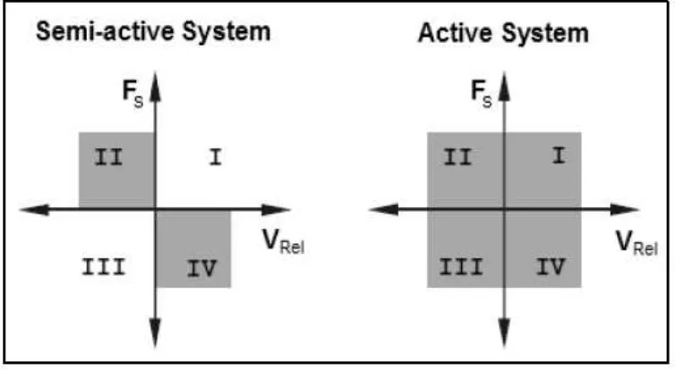
8 Another method to compare the difference between semi-active and fully active is about the working area. Based on the Figure 2.3 state by (ShahriarSarami, 2009), in a fully active system, the four operation areas are covered, because the force of the actuator can be applied to the system in direction or against the direction of the suspension movement. In spite of this, in a semi-active system, the force of the adjustable damper can be applied to the system only against the direction of the suspension movement. Thus, just two areas of the four operating areas are covered by this system.
Figure 2.3: Working area of the semi-active and fully active suspension (ShahriarSarami, 2009)
9 Figure 2.4: Hydro-pneumatic suspension with controllable throttle
(ShariarSarami, 2009)
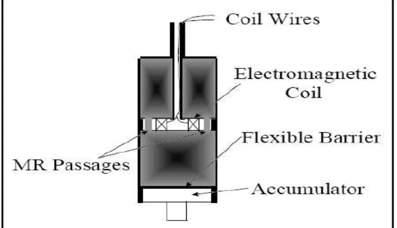
Next, about MR damper suspension that uses viscosity principle hydraulic fluid instead of cross-area of the throttle of a damper. This damper has two types. The types determined by the types of fluid used that is electro-rheological (ER) fluid or magneto-rheological (MR) fluid. Magnetic field is a controller to control the viscosity of the fluid. Each of the fluid has their own specialty. Figure 2.5 is shown about the model of MR damper in schematic illustration.
10 MR damper can response in the short time, it about of millisecond. This is important in a semi-active control system, because among all components of this control system, the time response of the actuator is the most limiting factors in order to create the proper control bandwidth (Mäkelä, 1999).MR dampers has priority to the ER dampers inpracticable application (Goncalves, 2001), because they can be directly operated by the electricity source of a vehicle.
Considered about the failure, semi-active system is less than fully active system in the aspect of operation. Passive damping is created by control damping force. Without building a critical situation in the vehicle, the efficiency will be decreased. The advantages of semi active system are the construction is not complicated, cheaper, and have low energy consumption. Based on these performances, semi-active system are usually preferred over fully active suspension. Besides, many car companies considered with semi-active in order to save their cost. For the heavy vehicles, semi-active suspensions are preferred particularly as a practicable way in order to improve their suspension performance (Efatpenah, Beno, & Nichols, 2000).
2.2.3 Conclusion for suspension
In the discussion above, for the vehicle performance chassis suspension intended to improve by using active suspensions. It is started with identified the component that involved in the active suspension. After that, types of suspension were described and do comparison with semi-active system and fully active system in order to choose the best suspension. Based on the (ShahriarSarami, 2009), Table 2.1 was created.