‘I hereby declare that I have read this project report and found its content and form to meet acceptable presentation standards of scholarly work for the award of
Bachelor of Mechanical Engineering (Thermal-Fluid)’
Signature :
Name of Supervisor : Mr. Shamsul Bahari Bin Azraai
Optimization of louvered plate angle using CFD method
AZMIR BIN ABU SAMAH
A report submitted in partial fulfillment of the Requirement for the award of the degree of Bachelor of Mechanical Engineering (Thermal-Fluid)
Faculty of Mechanical Engineering Universiti Teknikal Malaysia Melaka
ii
DECLARATION
I declare that this project report entitled “Optimization of louvered plate angle using CFD method” is the result of my own research except as cited in the references.
iii
iv
ACKNOWLEDGEMENT
First of all, my heartiest appreciation to my final year project supervisor, Mr. Shamsul Bahari Bin Azraai for his guidance, advice, support which has put me in a well study curved line which directly contributed thoroughly to the success of this project. His idea, experience and knowledge had been aspiring to me abundantly.
v
ABSTRACT
vi
ABSTRAK
vii
TABLE OF CONTENT
CHAPTER TITLE PAGE
DECLARATION ii
DEDICATION iii
ACKNOWLEDGEMENT iv
ABSTRACT v
ABSTRAK vi
TABLE OF CONTENTS vii
LIST OF TABLES x
LIST OF FIGURES xii
LIST OF SYMBOLS xiii
LIST OF ABREVIATION xiv
I INTRODUCTION 1
1.1 Problem Statement 3
1.2 Objective 3
1.3 Scope 4
II LITERATURE REVIEW 5
viii
2.1.1 Surface 10
2.1.2 Louvered plate performance 10 2.1.3 Flow visualization of Louvered-fin
In Heat Exchanger 12
2.2 Flow visualization of louvered plate/fin 13 2.2.1 Streamline and Streaklines 13
2.2.2 Pathline 13
2.3 Modified Louvers 14
2.4 Pressure drop 16
2.5 Computational Fluid Dynamics 18 2.5.1 The advantages of CFD over
field measurements 19
2.5.2 Problem-solving with CFD 21 2.5.3 CFD Governing Equation 22 2.5.4 Governing equation and
Numerical schemes 24
III METHODOLOGY 26
3.1 Construct a design 27
3.2 Workflow analyzing 27
3.3 CFD Tools Requirement 29
3.4 Creating the geometry 31
3.5 Meshing the surface 36
3.6 Computing the flow 40
IV RESULTS AND DISCUSSION 43
ix
4.2 Contour plot 43
4.3 Vector plots 45
4.4 Pressure 48
4.5 Velocity profile 50
V CONCLUSION AND 53
RECOMMENDATION
5.1 Conclusion 53
5.2 Recommendation 54
REFERENCE 55
x
LIST OF TABLES
NO. TITLE PAGE
2.1 Parameters of sample tested 6
3.1 Specify boundary type 38
xi
LIST OF FIGURES
NO. TITLE PAGE
1.1 Flat-tube heat exchanger 1
1.2 Air conditioning product 2
1.3 Type of fin 2
2.1 Schematic a louvered plate fin arrays showing duct
and louvered directed flow 6
2.2 A flat-tube and louvered fin heat exchanger 7 2.3 Typical louvered fin geometry with two and one flat
rows of tubes in the flow direction 8
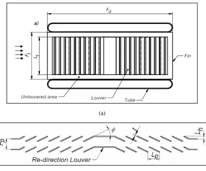
2.4 Geometrical parameter of louvered fin 9
2.5 Definition of modified louver geometry 14
2.6 Nusselt number distribution for modified louvers
Compare to a straight unmodified louver 15
2.7 Pressure drop at louvered plate 16
2.8 Pressure Drop vs. Flow Velocity 17
2.9 CFD Fluid Element for Calculating 23
3.1 Workflow analyzing 28
3.2 Creating the wind tunnel geometry 31
xii
3.4 Move/ Copy Volumes 33
3.5 Row of the louvered plate with 25° degree 34
3.6 Subtract Input 34
3.7 Before subtract 35
3.8 After subtract 35
3.9 Plot meshing Process 36
3.10 Meshing Process 37
3.11 Finished Meshing at front view 37
3.12 Specify boundary to each surface 38
3.13 Process Flow in FLUENT 40
3.14 Contours of static pressure (pascal) 41 3.15 Velocity Vectors Colored by Velocity magnitude 42
(m/s)
4.1 Contour of static pressure with 20 m/s at: a) Louver 45 Angle of 15°; b) Louver Angle of 25°; c) Louver
Angle of 35°;
4.2 Velocity vector with 20 m/s at: a) Louver 47 Angle of 15°; b) Louver Angle of 25°; c) Louver
Angle of 35° ;d) focus view at Louver Angle of 25°
4.3 Pressure Drop versus angle (15°, 25° and 35°) 49 4.4 Velocity moving through the louvered plate 50
xiii
LIST OF SYMBOLS
v = velocity, m/s
� = angle
� = distance,
� = Gravity
ℎ = height
= Length
o
= Degree
N = Newton
P = Pressure ,Pa
φ = Louver angle
Lh = Louver thickness
Ll = Louver length
Lp = Louver pitch
Lh = Louver height
Fp = Fin pitch
xiv
LIST OF ABREVIATION
CFD Computational Fluid Dynamics 2D Two – Dimensional
1
CHAPTER 1
INTRODUCTION
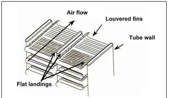
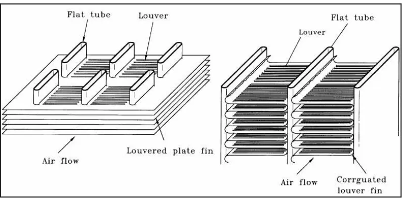
The louvered fin has been used heavily in the automotive and air conditioning industries for the last several decades. Louvered fins, rather than continuous fins, are commonly used in compact heat exchangers to break up boundary growth along the fins and increase the air side heat transfer surface area. The mechanisms that control heat transfer in a louvered fin heat exchanger provide the potential for reducing the heat exchanger’s size and weight. This reduction in size can clearly benefit many industries, including transportation, heating, and air conditioning.
2
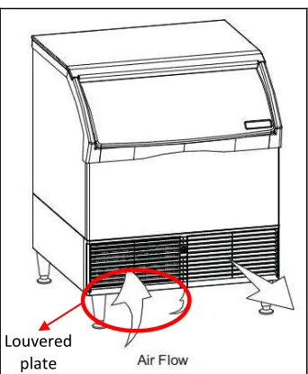
Figure 1.2: Air conditioning product
Types fin always used in the automotive and air conditioning industries can see in Figure 1.3.
Figure 1.3: Type of fin (Source: Jiehai Zhang, 2004) Louvered
3
1.1 Problem Statement
One particular type of compact heat exchanger for the louvered fin heat exchanger has been used heavily in the automotive and air conditioning industries. Over the last several decades, the majority of the work towards improving louvered fin exchanger efficiency has focused on designing more efficient fins by optimizing fin parameters like louver angle, fin pitch, louver pitch, and louver length. The majority of past research aimed towards improving louvered fin exchanger efficiency and has focused on optimizing various parameters of the louvered fin only.
The air velocity distribution for louvered fin heat exchangers in residential air conditioning installations is not very well documented today because it is difficult to measure accurately. In this study the louvered fin geometry will be determine the angle of louvered plate at different air velocity. In the same time the air velocity and pressure drop is determine with optimization the angle louvered plate using the CFD method. Pressure drop and air velocity results and comparisons of the different louvered angle and solvers are reported and discussed.
1.2 Objective
The objectives for this project are as below:
4
1.3 Scope
The scope for this project includes:
a. Literature study on overview of louvered plate design, geometry and CFD modeling and simulation
b. To study the application of CFD method. c. To construct the CFD louvered plate geometry.
d. To simulate numerically air flow through the louvered plate angle. e. CFD simulation and predictions.
Collect results and data
5
CHAPTER 2
LITERATURE REVIEW
On doing this study, there are some journal that been produce someone on previous time had been referred. The journal was based on their studied and finding on various titles. The previous studied was mostly conduct by grouping or coupled. The content of previous papers is related to this project title. Otherwise all these journals can be helped in completing the project till the objectives of the project can be achieved.
DeJong N.C and Jacobi A.M (2003) had presented a detail study of flow, heat transfer, and pressure drop for louvered fins. Louver-by-louver mass transfer data are acquired for Reynolds number from 130 to 1400. Pressure-drop data are obtained using a low-speed wind tunnel and local flow structured are visualized using dye injection in a water tunnel. Particular attention is placed on the role of vortex shedding in heat transfer enhancement. In contrast to recent studies for similar for. Set-strip arrays, vortex shedding is found to have less impact in louvered fin arrays. Several practical implications for louvered fin design and analysis are discussed.
6
follows the louvers rather than remaining in the ducts. The flow of the louvers is call flow efficiency.
Figure 2.1: Schematic a louvered fin arrays showing duct and louvered directed flow.
The goal of their paper is to present a more complete experimental description of flow and heat transfer in louvered fin arrays, with a focus on the physics important to thermal-hydraulic performance. A better understanding of flow and heat transfer interaction is possible through complementary experiments that provide louver-by-louver convection data, overall heat transfer, pressure drop, and detailed flow visualization.
Table 2.1: Parameters of sample tested. θ (degrees) Ratio of fin pitch to louver
pitch,(Fp /Lp) Number of fins
18 1.09 12
28 1.09 12
7
2.1 Louvered plate geometry
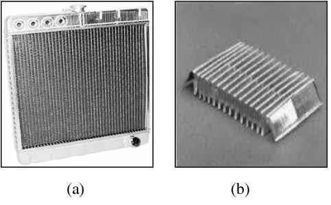
The availability of high-speed production techniques, consequently being less expensive than other interrupted fins, is an additional reason for their wide usage. They are associated with higher heat transfer coefficients than those for offset strip fins. Although the friction factor increase is greater than the heat transfer increase, the heat exchangers can be designed for higher heat transfer and the same pressure drop compared with those with offset strip fins by proper selection of the exchanger frontal area, core depth, and fin density. Louvered fin geometry can be considered as a combination of wavy and strip fin geometry (Figure 2.2).
(a) (b)
Figure 2.2: A flat-tube and louvered fin heat exchanger: a) Heat exchanger, b) Louvered fins (Source: Shah, 1999)
8
Figure 2.3: Typical louvered fin geometry with two and one flat rows of tubes in the flow direction (source: Wang et al., 1999b)
They are usually brazed, soldered or mechanically expanded to a flat, extruded tube, and formed into serpentine or parallel flow geometry. The louvered fin heat exchanger is built in the form of a combination of louvered fins and a single row of flat tubes with high aspect ratio or multiple rows of tubes with lower aspect ratio. Although not very common, the louvered fin and round tube combination can be encountered in practical applications.
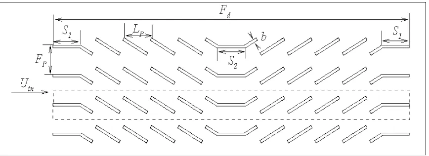
Basic geometrical parameters influencing the heat transfer and pressure drop in a louvered fin configuration are louver pitch Lp, louver angle φ , louver height Lh, louver
thickness t, louver length Ll, and fin pitch Fp (Figure 2.3).
9
coefficients than those of plain fins. The research performed on actual-sized louvered fin heat exchangers has been related to overall 2 heat transfer and pressure drop performance. Kays and London (1984) gave a compilation of such data for a large number of available heat exchangers at the time. Other studies of actual sized heat exchangers, like the one performed by Achaicha and Cowell (1988), showed performance data for heat exchangers for a wide range of influential parameters such as fin pitch, louver pitch, tube pitch, and louver angle. Although information like this is very valuable, it does not provide any details of the performance determining heat transfer and flow field mechanisms within the exchanger.
(a)
(b)