SMART HOUSE
VICTOR VOON CHUN HOWE
This report is submitted in partial fulfilment of the requirements for the award of Bachelor of Electronic Engineering (Computer Engineering) with Honours
Faculty of Electronic and Computer Engineering Universiti Teknikal Malaysia Melaka
i
UNIVERSTI TEKNIKAL MALAYSIA MELAKA
FAKULTI KEJURUTERAAN ELEKTRONIK DAN KEJURUTERAAN KOMPUTER
BORANG PENGESAHAN STATUS LAPORAN
PROJEK SARJANA MUDA II
Tajuk Projek : SMART HOUSE
Sesi Pengajian :
1 0 / 1 1
Saya VICTOR VOON CHUN HOWE mengaku membenarkan Laporan Projek Sarjana Muda ini disimpan di Perpustakaan dengan syarat-syarat kegunaan seperti berikut:
1. Laporan adalah hakmilik Universiti Teknikal Malaysia Melaka.
2. Perpustakaan dibenarkan membuat salinan untuk tujuan pengajian sahaja.
3. Perpustakaan dibenarkan membuat salinan laporan ini sebagai bahan pertukaran antara institusi pengajian tinggi.
4. Sila tandakan ( √ ) :
SULIT*
*(Mengandungi maklumat yang berdarjah keselamatan atau kepentingan Malaysia seperti yang termaktub di dalam AKTA RAHSIA RASMI 1972)
TERHAD** **(Mengandungi maklumat terhad yang telah ditentukan oleh
organisasi/badan di mana penyelidikan dijalankan)
TIDAK TERHAD
Disahkan oleh:
_____________________________________________ ___________________________________
(TANDATANGAN PENULIS) (COP DAN TANDATANGAN PENYELIA)
Tarikh: ……….. Tarikh: ………..
ii
“I hereby declared this report is result of my own effort except for works that have been cited clearly in the references.”
Signature : ………
Name : VICTOR VOON CHUN HOWE
iii
“I hereby declare that I have read this report and in my opinion this report is sufficient in terms of the scope and quality for the award of Bachelor of Electronic Engineering
(Computer Engineering) with Honours.”
Signature : ………
Name : ENGR. MOHD MUZAFAR BIN ISMAIL
Date :
iv
v
ACKNOWLEGEMENT
Before the final year project starts, I would like to thank everyone that has played such an important role for making my final year project 1 successful. It is all thanks for friends and the lectures that have been helpful and have been guidance for me during this semester. The main objective of Final Year Project is to help students to make used of the student knowledge that has been learned all this years. It help the student make use of the knowledge learned, to construct and modified the problem and solve the problem using the engineering method.
I would also like to thank my supervisor name Engr. Mohd Muzafar bin Ismail that guided me through my final year project. The support he gave me made me have patience to continue my project despite the difficulties that I faced during the period.
vi
ABSTRACT
vii
CONTENT
CHAPTER CONTENT PAGE
ACKNOWLEDGEMENT ABSTRACT
CONTENT LIST OF TABLE
LIST OF AMBREVIATIVES LIST OF APPENDIXS LIST OF FIGURE
v vi vii x xi xii xiii
I INTRODUCTION 1.1 Objective
1.2 Project Statement 1.3 Problem scope 1.4 Project methodology 1.5 Expected result
2 2 3 4 5
II LITERATURE REVIEW 2.1 Microcontroller
2.1.1 PIC
2.1.2 PIC18 high end core devices 2.2 Lighting Control System
2.2.1 Light Dimmer
2.2.2 Dimmer with Microcontroller
viii
2.3 Motion Sensor 2.3.1 Overview
2.3.2 Passive Infrared sensor (PIR) 2.3.3 Ultrasonic Motion Detector 2.4 Light Dependent Resistor (LDR)
2.4.1 Light Detector for Smart Home 2.4.2 Guide to Source Illuminations 2.4.3 Circuit for LDR Sensor 2.5 NTC Thermistors
2.5.1 What is thermistor 2.5.2 NTC Thermistor
2.5.3 Types of NTC Thermistors
2.5.4 Electrical properties – Resistance-Temperature Characteristics
2.6 Operational Amplifier – LM741 2.6.1 What is thermistor
2.6.2 Operational amplifier characteristics 2.6.3 Types of operational amplifier circuit 2.7 MAX232 Dual EIA-232 Driver/Receivers
2.7.1 RS232-MAX232-PC Connection diagram 2.8 Microsoft Visual Basic 2010
2.9 Commercial products
2.9.1 Control home temperature via smartphone 2.9.2 Passive energy application controls your heating from your phone
2.9.3 ZigBee plugwise smart socket measure energy consumption 11 11 11 13 14 14 14 15 16 16 17 17 18 19 20 20 21 24 24 25 26 26 26 28
III METHODOLOGY 3.1 Project Planning
3.2 Research on circuit and component for project
ix
3.3 Study Visual Basic IDE and Microcontroller programming
3.4 Construct the circuit and troubleshoot
3.5 Write the programming code for the microcontroller and visual basic
3.6 Integration of hardware and software 3.7 Testing the functionality of the project and
troubleshoot it 31 31 32 32 32
IV RESULT AND DISCUSSION 4.1 Introduction of result 4.2 Project description
4.3 Schematic and PCB layout for hardware 4.4 Visual basic IDE
4.5 Flow chart for microcontroller 4.6 PIC coding
4.7 Visual basic IDE coding 4.8 Prototype picture
4.9 Visual basic description 4.10 Discussion
33 34 39 44 45 46 50 51 54 54
V CONCLUSION AND RECOMMENDATION 5.1 Conclusion
5.2 Recommendations
5.2.1 Sensor recommendations
5.2.2 Interface between hardware and software recommendation
5.2.3 Software recommendation
x
LIST OF TABLE
NO TITLE PAGE
xi
LIST OF AMBREVIATIVES
FSR - File Select Register
IDE - Integrated Development Environment LED - Light Emitting Diode
LDR - Light Dependent Resistor
NTC - Negative Temperature Coefficient PIC - Programmable Interface Controller PIR - Passive Infrared Sensor
RMS - Root Mean Square
TRIAC - Triode for Alternating Current TTL - Transistor – Transistor Level
VB - Visual Basic
xii
LIST OF APPENDIXS
NO TITLE
1 2 3 4
MAX232 top view and construct circuit PIC16F877A pin diagram
LM741
xiii
LIST OF FIGURE
NO TITLE PAGE
2.1 Phase Controlling using a microcontroller 9
2.2 Waveform of Energetic Circuit 10
2.3 Operation and Sensitivity of Passive Infrared Sensors 12 2.4 Typical Sensitivity for Ultrasonic Motion Detector 13
2.5 Light Dependent Resistor (LDR) 14
2.6 LDR Sensor Circuit 16
2.7 NTC type Thermistor 16
2.8 R-T characteristics 19
2.9 LM741 operational amplifier 20
2.10 Internal diagram of operational amplifier 21
2.11 Internal block diagram 24
2.12 Unity gain inverting amplifier 21
2.13 Inverting amplifier circuit 22
2.14 Level detector or comparator circuit 22
2.15 Summing amplifier circuit 23
2.16 Different amplifier 23
2.17 MAX232 IC 24
2.18 2.19 2.20
RS232 - MAX232 – PC Connection diagram Passive energy application iPhone
ZigBee plugwise smart sockets
xiv
3.1 Flow chart diagram 30
4.1 LDR sensor 34
4.2 Thermistor sensor 35
4.3 Operational amplifier LM741 36
4.4 MAX232CPE IC 37
4.5 PIC16F877A 38
4.6 Light input schematic 39
4.7 Light output schematic 40
4.8 Fan input schematic 40
4.9 Fan output schematic 41
4.10 5V regulator layout 41
4.11 Microcontroller layout 42
4.12 4.13 4.14 4.15 4.16 4.17 4.18 4.19 4.20 4.21 4.22 4.23
Light input layout Light output layout Fan input layout Fan output layout Visual basic output
Flow chart for microcontroller Prototype overall look
LED light in off state LED light in on state Fan in off state Fan in on state Visual basic output
1
CHAPTER I
INTRODUNCTION
Home comfortability designates an emerging practice of increased automation of household and features in residential dwellings, particularly through electronic means that allow for things impracticable, overly expensive or simply not possible in recent past decades. The term may be used in contrast to the more mainstream "building automation", which refers to industrial uses of similar technology, particularly the automatic or semi-automatic control of lighting, doors and windows, Heating, Ventilation and Air Conditioning, and security and surveillance systems.
The techniques employed in home automation include those in building automation as well as the control of home entertainment systems, houseplant watering, pet feeding, changing the ambiance "scenes" for different events, and the use of domestic robots.
2
make major structural changes. These communicate via radio or infrared signals with a central controller.
1.1 Objective
In this project, the objective is to increase automation of household appliances and features in residential dwellings. Particularly through electronic make the things impracticable, overly expensive or simply not possible in recent past decades. This project is more concentrate particularly the automatic or semi-automatic control of lighting, doors and windows and air-conditioning. Since people spend more time at home. Hence, through this smart house, people will live in way that never expected, that is everything is just in a handy way and with a touch of a button. So it brings convenience to human live.
1.2 Problem statement
3
1.3 Project scope
4
1.4 Project methodology
Study about Visual Basic and Microprocessor
programming Research on circuit and component for our project
Start
Testing the functionality of the project and troubleshoot
it
Integration of software and hardware
Programming for the microcontroller and visual
basic
Construct the circuit and troubleshoot
5
1.5 Expected result
6
CHAPTER II
LITERATURE REVIEW
In this chapter, discusses regarding the background study of the project along with the literature review is performed and documented about the theoretical concept applied in completing the project. Background studies on the PIC controller and Visual Basic.
2.1 Microcontroller
2.1.1 PIC
7
PICs are popular with both industrial developers and hobbyists alike due to their low cost, wide availability, large user base, extensive collection of application notes, availability of low cost or free development tools, and serial programming capability. Microchip announced on February 2008 the shipment of its six billionth PIC processor.
2.1.2 PIC18 high end core devices
Microchip introduced the PIC18 architecture in 2000. Unlike the 17 series, it has proven to be very popular, with a large number of device variants presently in manufacture. In contrast to earlier devices, which were more often than not programmed in assembly, C has become the predominant development language.
The 18 series inherits most of the features and instructions of the 17 series, while adding a number of important new features, that is, PIC18 is much deeper call stack (31 levels deep), and the call stack may be read and written. It also has added the conditional branch instructions and indexed addressing mode (PLUSW). Also the FSR registers was extended to 12 bits, allowing them to linearly address the entire data address space. The additions of another FSR register can bring the number up to three.
The auto increment and decrement feature was improved by removing the control bits and adding four new indirect registers per FSR. Depending on which indirect file register is being accessed it is possible to postdecrement, postincrement, or pre-increment FSR or form the effective address by adding W to FSR.
In more advanced PIC18 devices, an "extended mode" is available which makes the addressing even more favorable to compiled code. A new offset addressing mode, some addresses which were relative to the access bank are now interpreted relative to the FSR2 register. The addition of several new instructions, notable for manipulating the FSR registers.
8
may be easily indexed—allowing more efficient re-entrant code. Microchip's MPLAB C18 C compiler chooses to use FSR2 as a frame point.
2.2 Lighting Control System 2.2.1 Light Dimmer
Research on light dimmer system has been done. Dimmers are devices used to vary the brightness of a light. By decreasing or increasing the RMS voltage and hence the mean power to the lamp it is possible to vary the intensity of the light output.
Although variable-voltage devices are used for various purposes, the term dimmer is generally reserved for those intended to control resistive incandescent, halogen and more recently compact fluorescent lighting.
Modern dimmers are built from silicon-controlled rectifiers instead of potentiometers or variable resistors because they have higher efficiency. A variable resistor would dissipate power by heat. By switching on and off, theoretically a silicon-controlled rectifier dimmer does not heat up.
2.2.2 Dimmer with Microcontroller
A digital control of light dimmer can use a simple microcontroller to do the controlling phase. The microcontroller has start by reading the dimmer set value through some specialized interfaces. The control value is typically 8 bit numbers where 0 means that light is off and 255 that light is fully on.
9
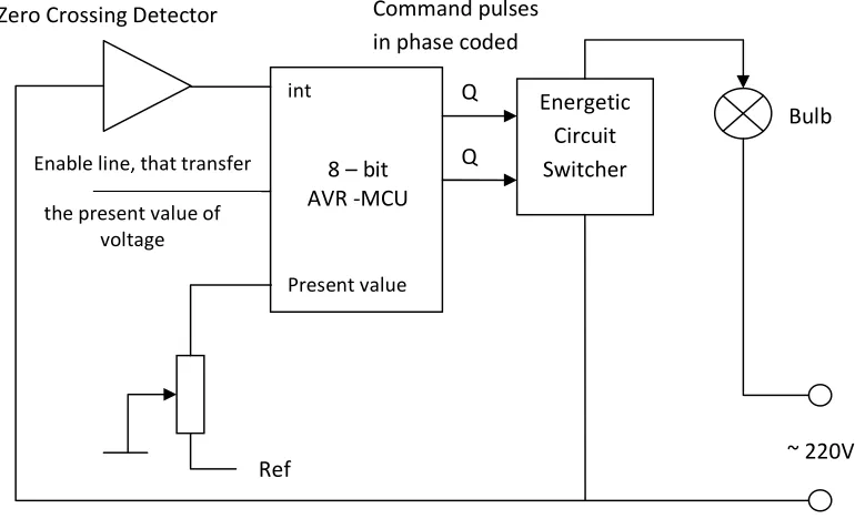
[image:24.595.123.508.243.477.2]Software loop is a quite simple and useful method if the time needed to execute each microprocessor command is definite. Another possibility is to utilize microcontroller timers. An interrupt is generated at every zero crossings and at every timer count. At every zero crossing the microcontroller loads the delay value to the timer and starts counting. When the counter time has elapsed it generates an interrupt. The timer interrupt routine sends a trigger pulse to the TRIAC circuit.
Figure 2.1: Phase Controlling Using a Microcontroller
The digital system, managed by a microcontroller can drive the dimmer. In this sense a preset information that specifies the voltage level applied on the bulb is necessary to be transmitted using the serial interface of controller or using a potentiometer that are connected to an analogue input line. A zero crossing detector circuit (ZCDC) gives to the controller the time reference for the phase control of command signal.
The interrupt generated by the ZCDC will treat by the controller triggering a timer or counter circuit that can be preset. It will generate a delay and when the time interval has finished the corresponding interrupt service routine generates a control
Energetic Circuit Switcher Zero Crossing Detector Command pulses
in phase coded
8 – bit AVR -MCU
int
Present value Enable line, that transfer