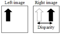
Figure 2. Features from left image are matched to features in the right image.
Figure 1. Horizontally aligned of stereo camera.
Visualization of Image Distortion on Camera
Calibration for Stereo Vision Application
*R. A. Hamzah, **S. F. A. Ghani, ***A. Din, ****K. A. A. Aziz
Faculty of Engineering Technology, UTeM76100 Melaka, Malaysia
*rostamaffendi, **shamsul, ***asri, ****[email protected]
Abstract— This paper presents a visualization of image distortion on camera calibration for stereo vision application. The 3D image plane in a group of target or image during the process of stereo pair calibration is also discussed. The extrinsic parameters of camera calibration can be viewed in 3D image or scene which contains the rotation and translation of vector. The error re-projection of a single image could determine the less error of distortion during the extraction of chessboard corner each image taken. The distortion model also generates an error coordinate system in pixel value. The 3D image will viewed the result and output of extrinsic parameters during the calibration process.
Keywords- camera calibration; Tsai’s algorithm; rotation; stereo geometry; stereo camer; image translation
I. INTRODUCTION
All the process of camera calibration is normally performed by first assuming a simplified model for both the camera and the distortion of resulting images and then statistically, usually fitting the distortion model to the observed distortion. Once the distortion has been modeled, it can be applied to the distorted image to correct it. An idealized pin hole camera model and radially symmetric lenses distortion are the usual modeling assumptions. Many calibration techniques also take into account distortion created by the digitization effects of the stereo camera. These effects are modeled along with the optical distortion and together account for the overall distortion observed in the acquired digital image. Once a model of the camera and distortion have been chosen they are fit to the real stereo camera by comparing where points of accurately know real world coordinates appear in the image and where they would appear if there was no distortion [1].
The error is minimized over as many points as is reasonable to fit distortion correction function to the distortion observed in the test scene. This distortion correction function, when applied to a raw image, reduces the distortion and what appears as a straight line in the real world appears as a straight line in the image [2]. In order for stereo correspondence techniques to work properly and for the range results that they yield to be precise and representative of the real world, the effects of the stereo camera distortion must repeatedly be accounted for. Usually, stereo vision systems use cameras that are horizontally aligned. That is, cameras are placed at the same elevation as shown in Figure 1.
II. CAMERA CALIBRATION
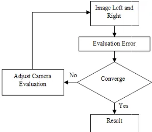
Figure 3. Flowchart of camera calibration for Extr After stereo cameras installation, these be calibrated. In order for stereo correlatio work accurately and for the range results tha accurate and representative of the real wor the camera and lens distortion must often b The process of camera calibration is genera first assuming a simplified model for both th distortion of resulting images and then sta the distortion model to the observed disto distortion has been modeled, it can be applie image to correct it [3]. The image processi use this result to get the accurate disparity model of the camera and distortion have b are fit to the real camera and lens by compar of accurately know real world coordinate image and where they would appear i distortion. The error is minimized over as m reasonable to fit distortion correction distortion observed in the test scene [4]. correction function, when applied to a raw the distortion and what appears as a straigh world appears as a straight line in the image.
A. Method of Camera Calibration
Note that the purpose of camera calibra improve the transformations, based on m coordinates, where one more often transformation to map coordinates from system to another. Tsai’s method for ca recovers the interior orientation, the exterio power series coefficients for distortion, and factor that best fit the measured im corresponding to known target point coo done in stages; starting off with closed fo approximation of some parameters and iterative non-linear optimization of simultaneously using these estimates as start
Importantly, it is error in the imag minimized. Details of the method are dif targets than for targets occupying some v Accurate planar targets are easier to make, limitations in camera calibration [4]. The flo
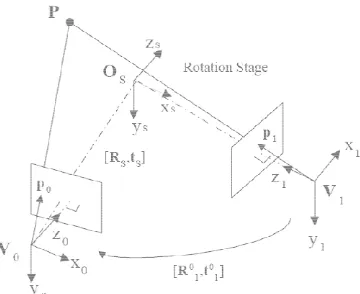
Figure 4. Stereo geometry of rinsic Parameters
cameras have to on techniques to at they yield to be rld, the effects of be accounted for. ally performed by he camera and the atistically, fitting ortion. Once the ed to the distorted
ing software will y values. Once a been chosen they ring where points es appear in the
f there was no many points as is
function to the . This distortion w image, reduces ht line in the real
.
ation is trying to measurements of n uses known
one coordinate amera calibration or orientation, the d an image scale mage coordinates
rdinates. This is orm least squares ending with an
all parameters ting values [5]. ge plane that is fferent for planar volume in space. but lead to some owchart Figure 3
below shows the steps of st programming in matlab [6]. The fir images in digital form and start to e the images of left and right. If the each other then the system will camera evaluation until they conver parameters will be used as a result be used in rectifying process [7]. calibration of stereo camera with calibration of rotation stage facilita view range images into a common paper using the Tsai's calibrati calibration pattern which contains se A focus calibration with respect to object is also presented. A stereo translation stage to implement the p of the stereo camera is done b Consider a point P in Figure representations Pl and Pr in the le coordinate systems. Then the tran coordinate systems is:
P
Where, and are rotation from the left to the right cam respectively. The translation stage horizontal direction x-axis in camer Therefore, there is little error on ep search stereo correspondence on ep direction. When there is an error in in camera coordinate, it can be man the translation stage to minimize geometry of the stereo camera syst stereo camera B is 60 mm and the f f is 15.35 mm. The focal length wa non-coplanar camera calibration tec 3D point P and its projection poin shown in Figure 4. If finding ano image plane which is the correspond by stereo matching algorithm the v
f camera calibration
tereo pair calibration’s rst step is to get a set of valuate the error between images are not converge adjust the value of the rge. The adjusted value or
for calibration process to This paper presents the the rotation stage. The ates registration of
multi-coordinate system. This ion technique using a everal controls points [8].
multiple distances of an pair is installed on the arallel stereo. Calibration by Tsai's algorithm [8].
4 in 3D space, its eft and the right camera nsformation between two
and translation matrices mera coordinate system,
be conclude as and xpl and xpr are the x co points pl and pr respectively.
B. Rotation Stage Calibration
Rotation stage calibration is importan multiple range images. This calibration give parameters between the camera coordinat rotation coordinate system. These paramete to register all partial 3D shapes into a com system and to integrate them. An accurate c rotation stage gives better performance for integration of multiple range images. A ca which has several control points is used fo stage. Since several stereo images of an ob every θ degree interval around an object, images of calibration pattern are also tak difference. By estimating calibration pa register two sets of 3D control points as clos partial shapes of the object into a common c also can be registered. Calibration for each system is done using Tsai's algorithm. calibration pattern is placed on the rotation s Two sets of stereo images are taken wit difference. Let V0 and V1 denote the coord the two views of directions and Vw de coordinate system. Let a control point in Vk and 1, and Pw be the same point represent coordinate system. Then transformations coordinate system to each camera coordinate
Where and are rotation and tran between two coordinate system as shown order to register all partial shapes to a coordinate system, it is necessary to find th between the common view coordinate system the rotation stage coordinate system. Let rotation and the translation matrices betw stages coordinate system and the camera co The transformation between two view d expressed as
Figure 5. Multiview geometry o
Figure 6. Rotation and translation o oordinates of the
nt for registering es transformation te system to the ers are later used mmon coordinate calibration of the r registration and alibration pattern or calibrating the bject are taken at two consecutive ken with θ angle arameters which se as possible, the coordinate system h view coordinate A checkerboard stage [9].
th θ degree angle dinate systems of enote the world
br Pk, where k=0 ted by the world from the world e systems are: ween the rotation oordinate system. directions is also
From equation above,
C. Extrinsic Parameters
To obtain both extrinsic paramet the stereo camera system, the Tsai m as calibration pattern. The process o be divided into three steps. Firstly t twenty images, then the extraction o in each image with 4x4 matrixes fr compute the external parameters val process for stereo vision, the referen at the epipolar line. A simplifyin vision is that epipolar geometry exi be matched along epipolar lines cameras these lines are parallel to t and translation of vector is the outpu These output will be viewed in3D location.
f stereo coordination
Figure 7. An extraction of chess board corner about 4x4
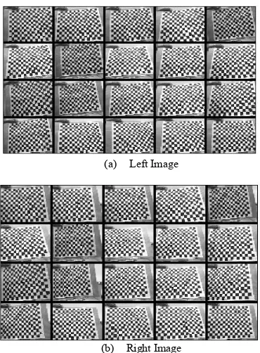
(a) Left Image
(b) Right Image Figure 8. The projection of stereo image
III. 3DTRANSFORMATION MATRIX
The basic element of the stereo vision theory is triangulation [11](Wong, 1975). As shown in Figure 8, a 3D point can be reconstructed from its two projections by computing the intersection of the two space rays corresponding to it. The 3D location of that point is restricted to the straight line that passes through the center of projection and the projection of the object point. Binocular stereo vision determines the position of a point in space by finding the intersection of the two lines passing through the center of projection and the projection of the point in each image. In this section, this paper describes a calibration technique of a vision camera. It can be considered as an estimation of a projective transformation matrix from the world coordinate system to the camera's image coordinate system. For example the ( , 1 of a 3D point in space and coordinates (xc, yc,1) of its projection on the 2D image plane, a 3X4 matrix M can be written according to the equation:
1 With
The matrix M is defined up to an arbitrary scale factor and has only 11 independent entries. Therefore it needs at least 6 world image points and their matching points in the image plane. If the calibration pattern is used, for example a checkerboard pattern, it have more correspondences and M can be estimated through least squares techniques.
IV. EXPERIMENT RESULT
Figure 10. The example projection error of raw image
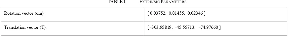
Figure 12. Visualization of image distortion during calibration process TABLE I. EXTRINSIC PARAMETERS
Rotation vector (om): [ 0.03752, 0.01455, 0.02346 ] Translation vector (T): [ -303.95819, -45.55713, -74.97660 ]
Left Camera Right Camera
Figure 11. 3D image of stereo camera and chessboard position for extrinsic parameters
ACKNOWLEDGMENT
The authors would like to acknowledge the funding from Short Term Grant of Universiti Teknikal Malaysia Melaka.
REFERENCES
[1] G. Eason, B. Noble, and I. N. Sneddon, “On certain integrals of Lipschitz-Hankel type involving products of Bessel functions,” Phil. Trans. Roy. Soc. London, vol. A247, pp. 529–551, April 1955. [2] S. Rusinkiewicz, O. Hall-Holt, and M. Levoy, \Real-Time 3DModel
Acquisition," Proceedings of SIGGRAPH 2002.
[3] CMU/FRC “Final Report: Autonomous Cross Country Navigation Technologies” Field Robotics Center or the Robotics Institute at Carnegie Mellon University, 1996.,
[4] Tsai, R.Y., An Efficient and Accurate Camera Calibration Technique for 3D Machine Vision. Proceedings of IEEE Conference on Computer Vision and Pattern Recognition, Miami Beach FL, 1986, pp. 364–374.
[5] B. Curless and M. Levoy, \Better Optical Triangulation through Spacetime Analysis," IEEE International Conference on Computer Vision, pp. 987-994, June 1995.
[6] R A Hamzah, H. N Rosly, R. Rahim, Depth Evaluation in Selected Region of Disparity Mapping for Navigation of Stereo Vision Mobile Robot, IEEE Symposium on Industrial Electronics & Applications, Penang, Malaysia, October 2010,
[7] Rovira-Más, F., Q. Zhang, and J. F. Reid., 2004. Automated agricultural equipment navigation using stereo disparity images. Trans. ASAE 47(4).
[8] Tsai, R, “A Versatile Camera Calibration Technique for High Accuracy 3D Machine Vision Metrology Using Off the Shelf TV Cameras and Lenses”, IBM Research Report, RC 11413, 1985. [9] R. Y. Tsai, \A Versatile Camera Calibration technique for
High-accuracy 3D Machine Vision Metrology using O_-the-shelf TV Camera and Lenses," IEEE Journal of Robotics and Automation, Vol. 3, No. 4, pp. 323-344, 1987.