Numerical Method Approaches in Optical Waveguide Modeling
Mohd Muzafar Ismail
a, Muhammad Noorazlan Shah Zainuddin
bFaculty of Electronic and Computer Engineering, University Teknikal Malaysia Melaka,
Hang Tuah Jaya 76100 Durian Tunggal Melaka, Malaysia
a[email protected], b[email protected]
Keywords: Optical waveguide, normalized propagation constant, effective refractive index
Abstract. Optical waveguides have been known as basic structure in integrated optics. The result of waveguide analysis is very useful to apply before fabrication process begins. In this paper, optical propagation characteristic of straight waveguide on light intensity distribution within the structures have been investigated at 1.55 micrometer waveguide. The normalized propagation constant b and effective refractive index neff conditions have been considered for the
straight waveguide for single mode propagation. Both the propagation characteristic can be calculated efficiently on the personal computer by using MATLAB programming. The analysis has been analyzed using a numerical method based on finite difference method approach. The result of optimization analysis of waveguide according to the parameter study can help in practical work in designing an optical waveguide easily.
1.0 INTRODUCTION
An optical waveguide is a physical structure that guides electromagnetic waves in the optical spectrum. Waveguides used at optical frequencies are typically dielectric waveguides, structures in which a dielectric material with high permittivity, and thus high index of refraction, is surrounded by a material with lower permittivity. The structure guides optical waves by total internal reflection. Since the invention of laser in 1969 [1], the optical signal starts to use for carrier in telecommunication. It was in 1960, Miller introduced the term ‘Integrated Optics’. It was involve the realization of the optical and electro optic elements which may be integrated in the large numbers on one chip means of the same processing techniques used to fabricate integrated electronic circuits. Demand for integrated optic circuits comes from the side of the light wave communication system which required in addition to laser source, components such as optical switches, modulators and power splitters.
Optic communication systems widely operate in the wavelength windows at 850nm, 1300nm and 1550nm. For a low loss transmission system, the optical loss due absorption from ultra violet (UV) and infrared (IR) region must minimize at operating wavelength and the system bandwidth will be increase. Thus, operation wavelength at 1550 nm is the best wavelength can maximize the bandwidth system with low attenuating loss.
The buried waveguide is a very important component and suitable for integrated optical technologies, finding widespread and significant inferometers, splitters, switches and also as an optical interconnects such as bends and junction. The higher index guiding layers are selectivity formed near subtracts surface by metal in diffusion, ion exchange, on implantation and light beam radiation. The buried type of channel waveguide has the advantages that the propagation loss in typically lower in 1 dBm with smooth surface. It’s usually suitable for bend waveguide with small
waveguide wall roughness [1].
There are several types of technique to analyze the optical waveguide, and those techniques can divided into analytical and numerical methods. For the numerical techniques, various approaches such as scalar and vectorial finite difference, scalar and vectorial finite element and beam propagation method are applicable. Amongst, finite difference method is preferred due to easier programming task.
The finite difference method (FDM) is a simple numerical technique used in solving problem that uniquely defined by three things ,firstly partial differential equation such as Laplace’s or Poisson’ equation ,a solution region Boundary and/or initial conditions. The basic formulation that governs the propagation of light in the optical waveguide is a Maxwell’s equations and it derives to be below equation to obtaining e-field [5].
Matlab software as a tool to calculate the equation which Graphical User Interface (GUI)
was used and it make a friendly user and obtaining the result with faster and accurate. Click the
button CALCULATE, user will enter the parameter and about 10 second the result will out. Beside
that have many function of GUI and just click the button such as analysis, example and application.
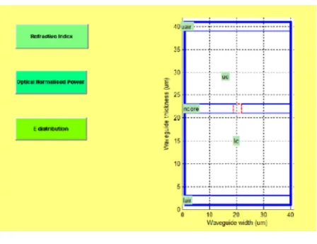
Figure 1(a) and Figure1 (b) shows the GUI application:
Figure 1(b) Calculation part in GUI
2.0 RESULT OF THE WAVEGUIDE WIDTH
Four ridge waveguide structures with different width w were simulated at 2.5 m, 3 m, 3.5 m and 4 m. Other parameters were set to be constant where total thickness of core layer is 1 m (t = 0.1 m, h = 0.9 m), upper cladding refractive index (air) = 1, core refractive index (GaAS) = 3.44, and bottom cladding or substrate refractive index (AlGaAs) = 3.36. Because of this work the ridge waveguide is operate in single mode, so the value of ridge width is must less than 4.7 m. The results are listed in Table 3.
Table 3 Comparison with difference ridge width
Guide Width, w ( m) neff b
a 2.5 3.39149 0.390790
b 3.0 3.39488 0.433166
c 3.5 3.39701 0.459717
d 4.0 3.39843 0.477431
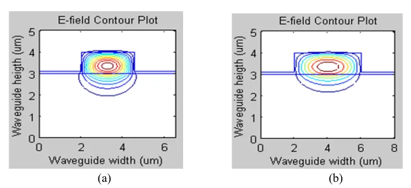
this figure, it shows that when the width w is high, the field distribution will converge and the electric field energy will radiate into core. The performance will improve as the ridge width increases, due to stronger lateral confinement. But for single mode, ridge width must less than 4.7 m.
(a) (b)
Figure 4 (a) and (b) Contour of E field when varies the width
3.0 CONCLUSION
The iterative method applying of the finite difference method can be accepted as one of the method to search for plotting electric field distribution. In the integrated optical circuit, the optimum design of ridge channel waveguide should support with low loss and strongly optical confinement for practical implementation. A good design of the ridge channel waveguide is intended to limit propagation loss and the transition losses.
4.0 REFERENCES
[1] DO-Won Kim, Seung Ho Ahn, Inkuicho,Dong-Ming Im, Muslim .S, Hyo-Hoon Park,2009.Thermally stable polymeric waveguide using uv-curable resins for optical printed-circuit board. Advanced Communication Technology 11th International Conference.
[2] Yong Gao,Song Feng,Yun Yang,2008.Research on the propagation mechanism and loss of ridged SiGe-Oi optical waveguide.Solid-state Integrated-circuit Technology –International Conference.
[3] N. Mohd Kassim, A. B. Mohamad, and M. H. Ibrahim, “Optical Waveguide Modeling Based on Scalar Finite Difference Scheme”, Jurnal Teknologi, Universiti Teknologi Malaysia, Jun 2005, pp. 41-54
[4] N. Mohd Kassim, A. B. Mohamad, A. S. Mohd Supa’at, M. H. Ibrahim, and S. Y. Gang, “Single Mode Rib Optical Waveguide Modeling Techniques”, RF and Microwave Conference, October 2004, pp.272-276