International Conference on Instrumentation, Communication and Information Technology (ICICI) 2005 Proc., August 3rd -5th , 2005, Bandung, Indonesia
SCA system (Subsidiary Communications Authorization) Implementation
of Text Transmission on Broadcasting System
Sudjadi1), Adian Fatchur R2)
1,2) Electrical Engineering Diponegoro University, Prof. H. Soedarto, SH Semarang
E-mail: [email protected]
Abstract – FM Radio broadcasting systems almost entirely have used the stereo system. A transmitter and receiver FM able to process the information signal with the frequency more than 75 kHz so that stereo system can be realized easily. Stereo broadcast bandwidth requirement is equal to 53 kHz, the rest bandwidth is applicable to be other that is by adding SCA system (Subsidiary Communications Authorization).
SCA used to deliver and accept the text data. Bandwidth of SCA system requires being limited in order not to bother the main broadcast program. Band from the limited SCA system used to deliver the digital information, for the reason need a digital modulation to optimize the bandwidth. Speed of data also require to be paid attention because the limited bandwidth. Data delivered have the start code so that only just certain receiver able to accept the data.
Information delivery of SCA system is by using frequency modulation with the 67 kHz carrier frequency. To limit the bandwidth hence require to be filtered before transmitted. Digital information beforehand converted to in the form of analogue with the digital modulation FSK. Baud rate of delivery and data acceptance is same that is equal to 600 bps. Data delivered use the start code in the form of certain character which not present at the computer keyboard. Data Acceptance method represent the process which have reverse from delivery process.
System have earned realized that is data sent acceptable successful and not bother the main broadcast program. By adding this system, modulation signal from stereo signal have to be decrease 11,11 %.
Keyword: SCA, asynchronous serial, FSK, FM, Broadcasting system
I. INTRODUCTION
Bandwidth from from transmitter FM in the reality not yet been exploited maximally. Bandwidth of sinyal stereo occupy until frequency 53 kHz, rest can be exploited for the delivery of other
International Conference on Instrumentation, Communication and Information Technology (ICICI) 2005 Proc., August 3rd -5th , 2005, Bandung, Indonesia
Target of our research is making hardware and also software module of transmitter and receiver text data, exploiting the rest of frequency band of radio FM by SCA/ Subsidiary Communications Authorization.
SCA represent one of the form system of communications simplex with the system of frequency modulation as mode or appliance to exploit the bandwidth at system of broadcasting FM. Information brought at system SCA can in the form of voice or data depended a system wanted side of broadcasting company.
Middle frequency from a modulator SCA seen from frequency domain located in to the spectrum of frequency of stereo signal. For the frequency of middle equal to 67 kHz and by maximal deviation 7,5 kHz [of] hence frequency spectrum for the system of this [is] visible theoretically [at] Picture 1.
Fig 1. spectrum of Frequency of system of broadcasting FM accompanied
With SCA
Structure element implementation SCA PLL (Phase Lock Loop)
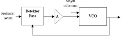
PLL consisted of [by] 3 elementary shares that is voltage controlled oscillator ( VCO), Phase Detector ( PD), and also filter the tress with the reinforcement. diagram of Block PLL showed at Picture 2. VCO is an oscillator able to yield the off the cuff frequency able to change as according to input tension. Output from VCO can be in
the form of waving sine of waving and also box other periodic waveform.
Fig 2 PLL Block Diagram
Detector Fasa ( PD) have two input and one output. If [both/second] input is periodic and have the same period hence component dc from output PD is proportional with the level of angle;corner difference between second of the periodic input sinyal
Third fundamental component from PLL [is] volute filter accompaniedly with the reinforcement. Existing Filter usually use the separate external component, in this way network PLL ready for harmonius cavity. Intention of network filter this is to obtain;get the component dc from output PD ( x(t)). Output PD consisted of [by] the frequency which chime in with the quantifying and also reduction of frequency vi(t) and vo(t)
Applying PLL as demodulator SCA
To accept the broadcast SCA of hence required by demodulator SCA demodulation to information signal SCA. System SCA using frequency modulation so that one of the way for the demodulation by using network PLL showed at Picture 3
International Conference on Instrumentation, Communication and Information Technology (ICICI) 2005 Proc., August 3rd -5th , 2005, Bandung, Indonesia
Input signal represent the composite signal result of demodulation at receiver FM. Band Pass Filter ( BPF) used to get away the sinyal SCA residing in to stereo signal bandwidth. the SCA signal is input to fase detector to be compared to an output frequency yielded by VCO. Because SCA use the system of frequency modulation so that output fase detector will change as according to change of frequency of sinyal SCA. Corrective Difference of tension ( error correcting voltage) correspond represent information SCA signal.
Frequency of Shift Keying
Binary FSK is a modulation by constant envelope which like conventional FM, except that in modulation FSK, modulation signal in the form of binary stream pulsa which vary among two level of tension diskrit so that differ from the change form which analogous wave continues.
a binary modulator FSK, center from frequency carrier shifted by binary data input. As its consequence, output at one particular binary modulator FSK is a function step at domain frequency. According to binary change sinyal input from a[n logic 0 to logic 1, conversely, output FSK shift among two frequency: a mark of frequency or logic 1 and a space of frequency or logic 0.
Fig 4. Binary Modulation FSK system
Active filter
Filtering is a network designed by] overcoming a certain frequency band and weaken all signal outside this frequency band. Active filter [is] filtering which is woke up by using active component, as does operational amplifier.
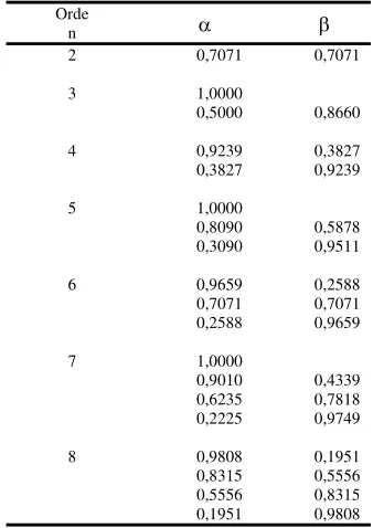
Filtering Butterworth have the comments which flatten at frequency passband from filtering and owning dilution which enough sharply at frequency stopband
Table1. Table Of Coefficient For The Scheme of Filter Butterworth
Orde
Filter to get away to lower active earn directly designed from coefficient filter the ( a and b). Function displace the configuraton filter to get away to lower one pole showed at Equation 1.
1
Function displace the configuraton filter to get away to lower one pole expressed in coefficient filter showed at Equation 2.
1
Function displace the configuraton filter to get away to lower two pole expressed in coefficient filter showed at Equation 3.
International Conference on Instrumentation, Communication and Information Technology (ICICI) 2005 Proc., August 3rd -5th , 2005, Bandung, Indonesia
Fig 5.a. Section one pole.
Fig. 5b. Section two pole
Fig 5. a,b Configuraton Network filter to get away to lower active reinforcement one
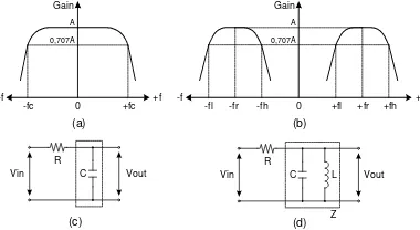
Network scheme filter the obtainable band pass from result of network filter transformation the low pass.
0 +fl +fr +fh +f
Fig. 6( a) Respon frequency filter the low pass ( b) Respon frequency filter the band
pass ( c ) Network filter the low pass modestly ( d) Filter the band pass [of]
result of transformation
In general function displace for the network of pass filter of order second bandwidth given with Equation 4.
2
H is a reinforcement constant 4.
Mikrokontroler AT90S8515
this Mikrokontroler Atmel AT90S8515 have the the following characteristic
1. Architecture RISC
2. 118 instruction of most one instruction cycle
3. 32x8 multipurpose register [job/activity]
4. 8 MIPS ( Mega Instructions per Second) at 8 MHZ
5. Can use of Ianguage C as Ianguage programming
6. Programmable Flash Memory [of] equal to 8 K Byte ( 1000 times cycle vanish / write
7. 512 bytes SRAM
8. 512 Bytes Programable EEPROM ( 100.000 cycle vanish / write the 9. Pemrograman locked for the
program of Flash and data security of EEPROM,
Transmitter-receiver SCA design system Peripheral of SCA transmitter
Hardware of SCA transmitter
Hardware design of SCA require to be specified by a things to be made a directive. such is :
1. frequency of carrier SCA [is] equal to 67 kHz + 0,2
2. maximal deviation frequency is 7,5 kHz
3. Baudrate equal to 600 bps.
International Conference on Instrumentation, Communication and Information Technology (ICICI) 2005 Proc., August 3rd -5th , 2005, Bandung, Indonesia
Fig 6. SCA Transmitter Block Diagram
For simpifly device of hence every block used by a network integrated the (IC). Network integrated by the MAX232 used as a computer Interface. Writer use the IC break evenly is TCM3105 as Modulator FSK. IC LM565 used as Modulator SCA. IC TL082 which in it represent the lasing operate for used as by block LPF 53 kHz and BPF 67 kHz, integrator.
Serial Interface RS232
To link the serial communications RS232 Computer with the system SCA [of] hence required [by] a Serial Interface RS232.
C1+
C1-C2+
C2-Vcc +5V TO +10 VOLTAGE DOUBLER
+10V TO -10 VOLTAGE INVERTER
V+
V+
5K 1
3 4
5
2
6 16
13 12
RS-232 input TTL/CMOS Output
Dari komputer Ke Modulator FSK
Fig. 7 serial Interface [of] RS232 by IC [is] MAX232
Modulator FSK
TCM3105 represent the modem FSK with the specification [of] according to standard of CCITT V.23 and BELL 202. Mode operate for the modulator selected in final duty scheme [is] according to standard CCITT. To arrange [it] hence needing to see the Tables 2
Table 2.Operation mode on FSK modulator TCM3105
Frequency
TRS TXR1 TXR2 Baudrate
mark space
L L L 1200 1300 2100
H L L 1200 1300 2100
L L H 600 1300 1700
H L H 600 1300 1700
L H L 75 390 450
H H L 75 390 450
L H H 75 390 450
the Operation mode used to arrange the baudrate at its modulator. In data delivery use the baudrate [of] equal to 600 bps so that TXR1 given [by] the low logic input (L) And TXR2 given [by] the high logic input (H).
SCA Modulator
To bring the sinyal information [of] above sinyal multipleks stereo [of] hence needed SCA modulator. SCA Modulator in principle use the frequency modulation with the carrier [of] equal to 67 kHz. the Sinyal Carrier [of] its frequency will fluctuate as according to its sinyal input. Sinyal of Input of modulator SCA [is] from analogous output [of] modulator FSK.
Fig 8. SCA Modulator block diagram
Network Bandpass Filter 67 kHz
International Conference on Instrumentation, Communication and Information Technology (ICICI) 2005
Fig 9. Band pass filter Butterworth second
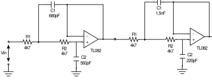
Filter to get away to lower 53 kHz use the category Butterworth with the cutoff frequency ( cut-off) 53 kHz. Order (n) filter [is] 4. Reinforcement filter designed [by] equal to one. Low filter 53 kHz shown by Fig. 10.
Fig 10. Low pass filter 53 kHz
Peripheral of Receiver SCA Hardware of Receiver SCA
Specification of receiver peripheral have to be adapted by transmitter. Specification for the receiver of SCA shall be as follows
1. acceptance frequency [of] equal to 67 kHz
2. Baudrate of data Acceptance equal to 600 bps
3. As penampil used by LCD 2 x 16 line.
Block formation forming a visible receiver SCA [at] Fig.11
Fig 11. Receiver SCA Block diagram
IC TL082 which in it use for operational amplifier; build the BPF 67 kHz. IC LM565 used for the Demodulator of SCA. IC break evenly [is] TCM3105 used as [by] Demodulator FSK. We use the Mikrokontroler ATMEL AVR 90S8515 to process the data.We LCD M1632 to display data.
Band-Pass Filter 67 kHz
Scheme BPF to filter the pelewat band ( BPF) 67 kHz for the receiver of SCA same as at transmitter.
Demodulator SCA
Block PLL used to develop demodulator SCA. Block PLL of there are IC LM565. Important matter to design a demodulator SCA by IC LM565 is parameter found on the IC
1. frequency of Free running 2. Loop Gain
3. Hold In range 4. Loop Filter
International Conference on Instrumentation, Communication and Information Technology (ICICI) 2005 Proc., August 3rd -5th , 2005, Bandung, Indonesia
difilter to get result of good demodulation. Information signal have the frequency 1300 Hz and 1700 Hz so that writer set mind on to use to filter to get away to lower equal to 2 kHz
Demodulator FSK
According to standard CCITT to arrange the mode operate for the acceptance of demodulator SCA using visible IC TCM3105 at Table 3
Table 3 Mode operate for the demodulator FSK at TCM3105
Frekuensi
TRS TXR1 TXR2 Baudrate
mark space
L L L 1200 1300 2100
H L L 75 390 450
L L H 75 390 450
H L H 600 1300 1700
L H L 1200 1300 2100
H H L 600 1300 1700
L H H 75 390 450
the Operation mode used to arrange the demodulator baudrate. In data acceptance selected [by] baudrate equal to 600 bps
Fig 12 Demodulator FSK with IC TCM3105
Acceptance conditioner
Acceptance conditioner function to deactivate the data of moment input [of] [there] no sinyal of input SCA. Output from demodulator FSK [is] random data when its input random signal. This matter it is of course will bother receiver system if the random data recognized by prefiks
Mikrokontroler AT90S8515
Mikrokontroler AT90S8515 used for the data process from output of demodulator FSK. To avoid the mistake of pencuplikan data [of] hence value of crystal frequency have to earn [is] precisely divided by 16(UBRR + 1) and quotient represent the original number ( without there [is] comma). Crystal used [by] [is] 1,8432 MHZ fulfilling all criterion [of]
Mikrokontroler AT90S8515 consisted of 4 port; A,B,C,D. Each can function as input and also as output. usage of Port AT90S8515 in this final duty [is] visible [at] Table 4.
Table 4. using AT90S8515 ports
Port AT90S8515 Use to
Port A PA0-PA2, PA4 – PA7 LCD Output
Port B PB0 - PB7 -
PC4 SCA signal detection
Port C
PC0, PC1, PC5, PC6, PC7 Keypad
PD0 receiver (RXD) pin
Port D
PD2 receiver (RXD) pin
Analyse SCA transmitter
Testing and Analyse The Serial Interface Block RS232
International Conference on Instrumentation, Communication and Information Technology (ICICI) 2005 Proc., August 3rd -5th , 2005, Bandung, Indonesia
Fig 13. Interfacing RS232 testing
Block of Modulator FSK testing
Photo form the sinyal output from block of modulator FSK [at] oscilloscope shown by Fig.14
Fig 14 a. output at input signal 0
Fig 14 b. Output at input signal 1
Testing and Analyse SCA Block Modulator
Modulator SCA contain block PLL and also block of generating of reference frequency. To know performance hence needing to see its output generating of reference Frequency represent the crystal oscillator which [is] later;then divided in order to become 67 kHz.
Fig 15. Output frequency generator 67 kHz
Photo form the sinyal of input and sinyal output from block of modulator SCA without input of modulator signal at oscilloscope shown by Picture 15.
Fig 16. Output signal SCA Modulator
Testing Block BPF 67 kHz
International Conference on Instrumentation, Communication and Information Technology (ICICI) 2005 Proc., August 3rd -5th , 2005, Bandung, Indonesia
give] its input frequency [is] 35 kHz until 100 kHz
Fig. 17 Band pass filter 67 kHz frequency respond
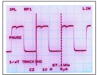
Photo of testing output oscilloscope from BPF 67 kHz with the input from output of modulator SCA which not yet modulation.
Fig 18 Output signal BPF 67 kHz (Input/output SCA modulator)
Testing and Analyse the Block LPF 53 kHz graph filter to get lower 53 kHz shown by Fig 19. This graph [is] represent the frequency graph to its gain.
Fig 19 Low pass filter 53 kHz respond
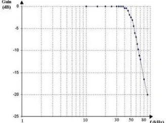
Testing and analyse SCA Receiver Testing and analyse BPF 67 kHz receiver graphic low pass filter 67 kHz respond as shown Fig 20.
Fig 20. Low pass filter 67 kHz frequency respond
International Conference on Instrumentation, Communication and Information Technology (ICICI) 2005 Proc., August 3rd -5th , 2005, Bandung, Indonesia
Fig. 21 Output VCO signal PLL demodulator SCA
Tension conduct the VCO will be corrected [by] if happened [by] the difference fase between output VCO with the input of block PLL ( at fase detector). this Corrective tension represent the sinyal information from block of demodulator SCA. Information signal still mixed with high frequency so that still required filter to get away to lower.
Testing low pass filter 2 kHz
Low pass filter 2 kHz function to obtain;get the result of demodulation signal of SCA demodulator.This graphic comments filter to get away to lower the audio as shown Fig. 22
Fig 22 Graphic respond low pass filter 2 kHz
Testing SCA Demodulator by FM signal SCA Modulator which used by a modulation input by output signal from modulator FSK with the frequency 1300 Hz or 1700. Result obtained from visible output demodulator SCA as shown Fig 23.
Fig 23 a. SCA modulator 1700 Hz signal modulated
Fig 23 b. SCA modulator 1300 Hz signal modulated
Testing and Analyse The Block of FSK Demodulator
International Conference on Instrumentation, Communication and Information Technology (ICICI) 2005 Proc., August 3rd -5th , 2005, Bandung, Indonesia
Table 5 Demodulator FSK testing result.
f (Hz) Keluaran f (Hz) Keluaran
Influence of SCA modulation to system composition
SCA require 10 % from total modulation so that the sinyal of total stereo audio required [by] [is] equal to 80 % cause 10 % used as pilot signal 19 kHz. So thatvisible clearer [at] Table 6.
Table 6 SCA Modulation system
Modulation
Mostly existing broadcasting radio station now use the stereo system without SCA. [Is] if we like to added with the system SCA [of] hence have to degrade the amplitude audio input signal equal to 10 % so that reduction audio quality equal to :
%
Testing Audio Distortion
In sure information delivery there [is] distortion. Distortion can be generated
from existence of noise and also existence of other sinyal [is] which follow delivered.
Table 7 Output Tuner FM distorsion with input sinusoid (not use SCA)
f (KHz) % Distorsi
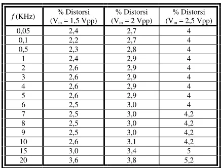
Table 8 Output Tuner FM distorsion with input sinusoid with SCA
f (KHz) % Distorsi
International Conference on Instrumentation, Communication and Information Technology (ICICI) 2005 Proc., August 3rd -5th , 2005, Bandung, Indonesia
equal to 10,18 % at the (time) of system given an optimal input modulation.
Testing of Distortion of Demodulator SCA Input signal which too big will influence the output from demodulator SCA. Input which too big distortion will result of demodulation SCA. This Distortion can cause the mistake convert the demodulator FSK so that data delivered - distorsion.
Table 9 Testing of SCA demodulator with maximal input before error conversion at SCA
modulator 1300 Hz input.
f (KHz) Vinmax
Table 10 Testing of SCA demodulator with maximal input before error conversion at SCA
modulator 1700 Hz input.
f (KHz) Vinmax
All above testing done with transmitter and receiver apart to bunch up if conducted with the distance which progressively far hence distortion that happened will be ever greater and will cause the demodulation mistake demodulator FSK.
Error Bit rate testing
Error Bit rate testing comparison accepted wrong with entire/all sent bit. Examination done] by delivering concevutive bit in the form of character with the certain quantity Result of test [is] not get a bit mistake accepted on the promise that distortion that happened still in level which small relative (Tables 14 and 15) and deviasi of transmitter frequency [not far exceed 75 kHz
CONCLUSION
1. Bandwidth rest of at one particular system of broadcasting FM can be exploited to deliver the data by broadcast [through SCA
2. Information signal experience of the distortion equal to 10,18 % effect of bandwidth exploiting rest because SCA use.
3. Digital sytem modulation FSK type applicable to deliver and also accept the data by baudrate 600 bps, BER [of] equal to 0 %. Low Baudrate [not the problem of considering system broadcast so that data [not need high-speed 4. To limit bandwidth of stereo signal
in order not to bother the sinyal SCA used filter to get away to lower 53 kHz
5. To limit wide bandwidth of SCA signal at transmitter and filter SCA signal receiver of hence used band pas filter 67 kHz.
6. PLL system used to modulator and demodulator SCA
7. Low pass filter 2 kHz have earned to give the censorship to high frequency signal accompanying information signal SCA that got signal which is clear of noise
International Conference on Instrumentation, Communication and Information Technology (ICICI) 2005 Proc., August 3rd -5th , 2005, Bandung, Indonesia
9. SCA require the modulation room equal to 10 %, addition of SCA at one particular system of broadcasting of FM stereo will degrade the sinyal of stereo modulation equal to 11,11 %.
10. Big distortion ( more than 50 %) [at] demodulator SCA will result the demodulation mistake by demodulator FSK.
REFERENCES
[1] Arthur B. William,”Electronic Filter Design Handbook”, McGraw-Hill Book Company, 1981.
[2] Dennis Roody, J. Coolen,” Komunikasi Elektronika”, J.1., Erlangga, Jakarta 1986. [3] Leon W/CouchII, “Digital and Analog
Comunication System”, Prentice Hall, 1997. [4] P. H. Simale, “Sistem Telekomunikasi I”, Edisi
kedua, Erlangga, Jakarta, 1995.
[5] Roger L.Freeman, “Telecomunication Transmission Handbook”, Wiley Series,1998. [6] Robert M., “Pengantar Telekomunikasi”, Elex
media Komputindo, Jakarta 1986.
[7] Wasito S.,” Data Sheet Book 1, Data IC Linier, TTL & CMOS ”, Elex Media Komputindo, Jakarta, 1985.
[8] Openheim,Alan V & Willsky,Alan, “Sinyal & System “. Jilid 2, Erlangga, Jakarta, 2001.
[9] Theodore S Rappaport, “Wireless Communication. Princip & Practice”, Prentice Hall. 1996.
[10] Wayne Tomasi, “Advanced Electronic Communication System”. 3th Edition, Prentice Hall. 1994.
[11] ,http://www.compolinc.com/. [12] ,ATMEL AVR (Data Sheet),
www.atmel.com.
[13] , http://www.adontec.com/.
[14] ,http://www.integrateddatacorp.com/. [15] ,www.rtcomm.com