Mass and Energy Balance Analysis of Methanol
Production Using Atmospheric CO
2
Capture with
Energy Source From PCMSR
Andang W. Harto1, Mella Soelanda
Department of Nuclear Energy and Engineering Physics Faculty of Engineering Universitas Gadjah Mada
Yogyakarta, Indonesia
1[email protected], 1[email protected]
Abstract—The rising of atmospheric CO2 concentration is the
major source to global warming system. Many methods have been proposed to mitigate global warming, such as carbon penalty, carbon trading, CO2 sequestration etc. However these
proposed methods are usually uneconomical, i.e. these methods do not produce economic valuable substances. This paper will propose a method to absorb atmospheric CO2 to produce
economic valuable substances such as methanol, dimethyl-ether, ethylene, several hydrocarbon substances and derivatives and several graphite substances. This paper is focused to methanol production using atmospheric CO2 capture. The overall process
is endothermic, thus a sufficient energy source is needed. To avoid more CO2 emission, the energy source must not use
conventional fuels. To assure the continuity of energy deliberation, nuclear energy will be used as the energy source of the process. In this paper, the Passive Compact Molten Salt Reactor (PCMSR) will be used as the energy source. The 460 MWth PCMSR is coupled with atmospheric CO2 capture,
desalination, hydrogen production and methanol production facilities. The capturing CO2 capacity is 7.2 ton/h of atmospheric
CO2. The valuable outputs of this system are 3.34 ton/h of H2,
34.56 ton/h of O2, 5.24 ton/h of methanol and 86.74 MWe of
excess electricity.
Keywords—CO2; methanol; economic produ; PCMSR
I. INTRODUCTION
The increasing of atmospheric CO2 concentration becomes
the most important environmental issue recently. The increasing of CO2 in the earth atmosphere gives the effect of
global warming which in turn causes global climate change [1]. The global climate change will cause many serious problems to human civilization. The examples of serious effects global climate are several natural disasters such as flooding, drought, harvesting failure, etc [2]. Several actions have been proposed and some of them have been implemented. The common goal of these actions is to reduce human made CO2 emission and to increase CO2 absorption of
both naturally or human made. Some of the examples of actions to reduce CO2 emission are: carbon penalty to every
entity who emit CO2 by using conventional energy resources
or other emitting CO2 process, carbon certificate and carbon
trading for every entity who able to substitute the emitting
CO2 processes with the other processes that emit less CO2 [3].
The examples of actions to increase CO2 absorption or to limit
the decreasing of CO2 absorption are deforestation penalty and
CO2 sequestration.
Most of these proposed methods do not produce real economics products, so the implementation of these actions will be viewed as economical burden of human civilization. The consequence, massive law enforcements are required to guarantee these actions to be success. It is interesting to invent a method of atmospheric CO2 increasing mitigation that able
to produce real economics valuable products. This will promote the global warming mitigation by natural human behavior.
II. BASIC THEORY A. Valuable substances from CO2
The CO2 can be reacted with H2 to produce methanol
(CH3OH) [4]. The methanol itself is a valuable substance. The
methanol also can be processes to produce more valuable substance. For example, the methanol can be dehydrated to produce dimethyl ether (DME) [5]. Dimethyl ether can be dehydrated to produce ethylene [6]. Ethylene can be polymerized to produce several synthetic hydrocarbon substances. All of these substances are economically valuable and also feedstock to produce more valuable substances. Thus CO2 is actually can be processed to produce several
economically valuable substances.
In recent technology industrial scale, CO2 is produced
form other economically valuable substances. Production cost consideration and limiting the availability these substances limit the amount of CO2 production, and thus limit the amount
of several valuable substances produced from CO2. If it can be
captured economically, the atmospheric CO2 will become
huge and cheap CO2 resources to produce several
B. Atmospheric CO2 capture
There are to types CO2 capture method. The first is CO2
capture from concentrated CO2 sources such as exhaust stack
of coal or oil fueled power plants or engines. The types of methods are relatively well established. However, these methods are not suitable to capture CO2 from diffuse sources
such as vehicles or other diffuse sources in which emit far more CO2 than concentrated sources around the world. Thus
the method to capture CO2 directly from earth atmosphere is
far more interesting.
Stolarrof et. al. propose a method to capture CO2 directly
from earth atmosphere [7]. In Stolarrof et al is proposal, CO2
will not be utilized after capturing but will be sequestrated. However the Stolarrof method is interesting due to the ability of capturing atmospherinc CO2 is a simple manner. This
method will be referred I this paper.
In Stolarrof method, atmospheric air is contacted with NaOH solution, and the CO2 will be captured by this following
reaction [7] :
2NaOH(aq) + CO2(g)
Na2CO3(aq) + H2O(l) (1)The Na2CO is then regenerated by this following reaction [7] :
Na2CO3(aq) + Ca(OH) 2(s)
2 NaOH(aq) + CaCO3(s) (2)Thus the CO2 is trapped in solid CaCO3. In original Stolarrof
proposal, the CaCO3 is directly sequestrated. This mean the
overall process is costly and unsustainable because need Ca(OH) 2 continually.
In this paper, the CaCO3 is regenerated by this following
reaction :
CaCO3(s)
CaO(s) + CO2(g) (3)The CaO is then reacted with water to obtain Ca(OH)2 with the
following reaction :
CaO(s) + H2O(l)
Ca(OH2)(s) (4)The overall process will be sustainable in term of NaOH and Ca(OH)2. However, it is useless if the CaCO3 regeneration is
done in atmospheric condition so the CO2 is released back to
atmosphere. In this paper, the CaCO3 regeneration must be
done in a reactor which supplied with hydrogen so the released CO2 will reacts with hydrogen to produce methanol by this
following reaction [4] :
CO2(g) + 3 H2(g)
CH3OH(g) + H2O(g) (5)The overall system of atmospheric CO2 capture followed by
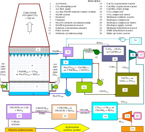
methanol synthesis, methanol dehydration, DME dehydration and synthetic hydrocarbon synthesis is shown at Fig. 1.
C. Hydrogen production
According to equation (4), hydrogen is needed to convert CO2 to methanol. Free hydrogen is unavailable naturally in a
sufficient amount. Thus free hydrogen must be produced from naturally abundant feed materials. Hydrogen can be produced from conventional energy resources by using steam reforming method [8]. However this method emit CO2 thus this method is
non suitable to the ultimate goal of mitigation of global warming by reducing atmospheric CO2 concentration.
Hydrogen can be produced by using water as feedstock with following reaction :
H 2O(l)
H2(g) + 0.5 O2(g) (6)The production of hydrogen from water does not emit CO2.
There are several methods to produce hydrogen from water. The high temperature steam electrolysis (HTSE) using solid oxide electrolyze cell is the efficient and low cost method for producing hydrogen from water [9][10]. This method is used as a reference method in this paper. Fig. 2 shows the schematic diagram of solid oxide electrolyze cell.
D. Energy Consumption
The overall reaction of capturing CO2 to become the final
product of methanol is endothermic, means input energy is needed.
The reaction (1) is exothermic with h0= -109.4 kJ/mole of CO2 and g0= -56.1 kJ/mole of CO2. With negative value of
0 g
, the reaction (1) is spontaneous. The reaction (2) is exothermic with h0 = -5.3 kJ/mole of Na2CO3 and g0=
-18.2 kJ/mole of Na2CO3. Also the reaction (2) is spontaneous.
The reaction (3) is endothermic with h0=177.99 kJ/mole of CaCO2. The reaction (4) is exothermic with h0= -65.3
kJ/mole of CaO. The reaction (5) or methanol synthetic reaction is exothermic with h0= -102.42 kJ/mole of CO2.
The reaction (6) or hydrogen production is the most energy consume reaction. Fig. 3 the energy needed to produce hydrogen from water per mole of hydrogen [11].
To produce 1 mole of methanol, 3 mole of hydrogen must be produced, 1 mole of CO2 must be captured, 1 mole of
Na2CO3, of CaCO3 and of CaO must be regenerated. Thus the
energy needed per mole methanol production in ideal condition is (3×250 - 109.4 - 5.3 + 177.99 - 65.3 - 102.42) kJ/mole = 645.79 kJ/mole. The energy needed in real condition is higher due to energy losses and the fact that not all of energy releases by the exothermic reactions are recoverable.
E. Energy Source
The fact that the overall reaction is endothermic means that an energy sources is needed. The fossil energy sources must be excluded because the emit CO2 and thus contra productive
with the ultimate goal to mitigate global warming by absorbing CO2.
1
2 3 4
5
7
8
REMARKS :
1 : Air blower 13 : CaCO3 regeneration reactor
2 : CO2 absorpban pool 14 : Ca(OH)2 regeneration reactor
3 : Air flow guide 15 : Ca(OH)2 slurry pump
4 : Air dan NaOH solution contact column 16 : CO2 compressor
5 : NaOH system 17 : CO2 compressor motor
6 : Demister 18 : Methanol synthetic reactor
7 : Chimney 19 : Hydrogen compressor
8 : Na2CO3 solution circulation pump 20 : Hydrogen compressor motor
9 : NaOH regeneration reactor 21 : Hyrdogen supply system
10 : Solution concentraton adjuster 22 : Methanol dehydration reactor
11 : Filter system 23 : DME dehydration reactor
12 : Solution circulation pump 24 : Make up water system
9 Udara keluar
(300 ppm CO2)
+ uap air
Air inlet (400 ppm
CO2)
Air inlet (400 ppm
CO2)
NaOH(aq)
Na2CO3(aq) 6
2 NaOH(aq) + CO2(g)
Na2CO3(aq) + H2O(l))
Na2CO3(aq) + Ca(OH) 2(s)
2 NaOH(aq) + CaCO3(s)
11
12
CaCO3(s)
CaCO3(s) CaO(s) + CO2(g)
13
CaO(s)
14
CaO(s) + H2O(l)
Ca(OH)2(s))
Ca(OH)(s)
(slurry)
15
CO2(g)
16 17
18 CO2(g) + 3 H2(g)
CH3OH(g) + H2O(g)
19 20
21 CO2(g)
H2(g)
CH3OH(g)
(metanol) 22
2 CH3OH(g)
CH3OCH3 + H2O(g)
CH3OCH3(g)
(dimetil eter / DME) 23
CH3OCH3 C2H4
+ H2O(g)
10
H2O(l)
C2H4(g)
(etilena)
Ethylene polimerization
Hydrocarbon synthetic product
24
Fig. 1. The overall system of atmospheric CO2 capture followed by methanol synthesis, methanol dehydration, DME dehydration and synthetic hydrocarbon
synthesis.
Electric Current Source
+ -
O2-
H2O feed (superheat steam)
O2 H2O + H2
1 2 3 4 5 6 1
Remarks : No. Component Material
1 Conductor bus Metal 2 Anode channel Oxygen 3 Anode Porous metal 4 Electrolyte Zr(Y) solid oxide ceramic 5 Cathode Porous metal 6 Cathode channel Steam and hydrogen mixture
REACTION : Cathode : H2O+ 2e- H2 + O2-
Anode : O2-
0,5 O2+ 2e -
Total : H2O H2 + 0,5 O2
Front view of cell
1 2
3
4 5
6 1
Top view of cell
Fig. 2. Schematic diagram of Solid Oxide Electrolyze Cell
Regarding the consideration of long term nuclear resources sustainability, the recent nuclear reactor technology that uses U-235 as fissile material is not recommended due to the natural U-235 resources scarcity.
The advanced breeder reactor utilizes more abundant fertile natural resources is more suitable. In this paper, the PCMSR (Passive Compact Molten Salt Reactor) which utilizes thorium nuclear fuel resources is applied to the energy source of the capturing CO2 to product methanol process.
F. PCMSR (Passive Compact Molten Salt Reactor)
PCMSR is variant of molten salt reactor that use liquid fluoride salt mixture of 70 % mole LiF, 29 % mole ThF4 and 1
% mole UF4. The thorium is converted to fissile U-233 which
undergoes fission reaction and produces the reactor power. The PCMSR use graphite as moderator and LiF-NaF-KF as intermediate coolant [12]. The schematic diagram of PCMSR is shown at Fig. 4.
11 11
C
D
Turbine Building Re a ctor Building
Auxilia ry Building
A
B
C
D
E
A : Reactor Module
B : Fuel Processing Compartment C : Fission Product Storage System D : Passive Cooling Pool
E : Turbine Generator Module F : Fuel Drain Tank
F
Fig. 4. The schematic diagram of PCMSR [12]
G. Calculation Result and Discussion
1) Energy balance of hydrogen production
Schematic diagram of energy balance of hydrogen production using High Temperature Steam Electrolysis using energy source from PCMSR is shown in Fig. 5. In Fig. 5, Q is heat energy, W is electrical energy and η is efficiency. The index of R refer to reactor, HE refer to heat exchanger for hydrogen production heat supply, TG refer to tubine generator, AC/DC refer to electrical supply system for electrolysis process, P refer to pump. In this analysis, it assumed that ηHE = 0.99, ηelectrolizer = 0.98, ηAC/DC = 0.97, ηTG =
0.53, ηP = 0.70 and ηBlower = 0.70.
The thermal power of PCMSR is assumed to be 460 MWth. The hydrogen production capacity is set as 1.2 kg/s (4.32 ton/h) or 0.6 kmole/s = 600 mole/s. The HTES is assumed to be operated at 1000 ºC. According to Fig. 3, g = 171 kJ/mole of H2 and h = 251 kJ/mole of H2 and thus
g h s
T = (251 – 171) kJ/mole = 80 kJ/mole of H2.
Electrolyzer
ηelectrolyzer
WTG
The gcomponent must be supplied as electrical energy. Thus the electrical power needed to supply the g component is pump, recirculation water pump and gas mixture blower. The calculated overall water pumping power is small, i.e. 0.4 kWe and the calculated blower power is 2 MWe. Thus the total electrical power to be supplied for overall electrolyze process is
The
T
s
component must be supplied as heat energy from reactor. The electrical energy loss in electrolizer will become heat energy and thus the thermal power to be supplied byHeat also must be supplied to evaporate the feed water. To produce 0.6 kmole/s of hydrogen, 0.6 kmole/s or 10.8 kg/s of water is needed. The heat of evaporation of water is 2400 produce 0.6 kmole/s of hydrogen is
MWth the overall turbine generator efficiency of 0.53. A part of this thermal power must be supplied to the hydrogen production system, i.e. Q1 = 72.56 MWth. Thus the thermal power supplied to the turbine system is
MWth
The electrical output of turbine system is therefore
0.53 387.44
MWe 205.34MWe electrical power of
205.34 110.36
MWe94.98MWe2) Energy balance of atmospheric CO2 capture
The atmospheric CO2 capture system is assumed to be
designed capture 2 kg/s (7.2 ton/h) or 45.45 mole/s of CO2.
The ambient air inlet is assumed to contain 400 ppm of CO2.
The capture system is assumed able to reduce the CO2 content
to become 300 ppm as the air flows out from the capture system. This mean the mass flow rate of air is 20 ton/s.
To capture 45.45 mole/s of CO2, 45.45 mole/s of Na2CO3,
CaCO3 and CaO must be regenerated. The energy released
from exothermic reaction of the capturing CO2 cycle are
assumed to be unrecoverable. Thus the energy needed for capturing CO2 process cycle is equal to the energy needed of
the endothermic reaction of this cycle, i.e. reaction (3). The energy is supplied in the form of heat energy. It is assumed that the heat energy is supplied via electrical heater, which the electrical is supplied by the extra electrical power of the
The electrical energy also must be supplied for air blower and slurry pumps. The pumping powers are small. The calculated pumping power of NaOH solution is 0.67 kWe. The calculated pumping power of Na2CO3 solution is 0.67 kWe.
The calculated pumping power of NaOH-CaCO3 slurry is 1
kWe. The calculated pumping power of CaCO3 slurry is 0.68
kWe. The calculated pumping power of CaO slurry is 0.45 kWe. The calculated pumping power of Ca(OH)2 slurry is 0.64
kWe. Th calculated pumping power of H2O make up is 0.22
kWe. The calculated air blower power is 2.67 kW. Thus the overall air blower and pumping power of the capturing CO2
cycle is 7.00 kWe.
Electrical energy also must be supplied for the operation of mixer agitators in Na2CO3 regeneration reactor, CaCO3
regeneration reactor and CaO-water reactor. The calculated mixer agitator power of Na2CO3 reactor is 18.33 kWe. The
calculated mixer agitator power of CaCO2 regeneration reactor
is 30 kWe. The calculated mixer agitator power of CaO-water reactor is 3.55 MWe. Thus the total mixer agitator power is 46.88 kWe.
Therefore, the total electrical power to be supplied to the atmospheric CO2 capture system is
8.26 0.007 0.047
MWe 8.32MWe3
pupm agitator C W W W W
3) Energy balance of methanol synthesis
compression is 5.58 kW. Thus the total electrical power must be supplied for compressor system is
kWe 75 . 5
compressor W
4) Overral energy and material ballance
The total electrical power needed for overall process is
MWe 6 . 118
MWe 00575 . 0 8.23 110,36
E C compressor process W W W W
Therefore the surplus of electrical power is
205.34 118.6
MWe86.74MWe TG process surplus W W W
The surplus electrical power can be supplied to commercial electric consumers or commercial grid.
This atmospheric CO2 capture system is assumed to have
capturing capacity of 7.2 ton/h (45.45 mole/s) of CO2. All of
the captured CO2 is converted to methanol. Thus according to
reaction (5), the production capacity of methanol is 45.45 mole/s or 5.24 ton/h of methanol.
To produce 45.45 mole/s of methanol, according to reaction (5), 3 × 45.45 mole/s = 136.35 mole/s oh hydrogen is needed. However, the hydrogen production capacity of the HTSE system powered by 460 MWth PCMSR is 600 mole/s of hydrogen. Thus there is an excess hydrogen production of (600 – 136.35) mole/s = 463.65 mole/s. The 463.65 mole/s or 3.34 ton/h of the excess can be considered as the hydrogen commercial product.
According to reaction (6), the HTSE with production capacity of 600 mole/s of hydrogen produce 0.5 × 600 mole/s = 300 mole/s of oxygen by product. The 300 mole/s or 34.56 ton/h of the by product can also considered as the commercial oxygen product.
III. SUMMARY
It can be summarized that the global warming mitigation is not always economical burden for human civilization. It is possible to mitigate global warming as well as produce several economics valuable product from this mitigation action. The atmospheric CO2 capture is endothermic reaction in overall.
Thus the key of this process to be success is the availability of the abundant, cheap and non CO2 emitter energy sources. The
MSR that utilizes abundant thorium resources is the prominent candidate of the energy source of this system. The anayisis has been performed for 460 MWth PCMSR which is coupled with atmospheric CO2 capture, desalination, hydrogen
production and methanol production facilities. For the capturing CO2 capacity of 7.2 ton/h of atmospheric CO2, this
system can produce valuable outputs of 3.34 ton/h of H2,
34.56 ton/h of O2, 5.24 ton/h of methanol and 86.74 MWe of
excess electricity.
References
[1] US EPA, Climate Change Science Overview, US Environmental Protection Agency (US EPA), 14 June 2012.
[2] Cramer, W., et al., Executive summary, in: Chapter 18: Detection and attribution of observed impacts (archived 18 October 2014), pp.982-984, in IPCC AR5 WG2 A 2014
[3] Robert N. Stavins (2007). "A U.S. Cap-and-Trade System to Address Global Climate Change" (PDF). The Hamilton Project. Retrieved 2014-07-26.
[4] C.A.Huff and M.S. Stanford, Cascade Catalysis for the Homogeneous Hydrogenation of CO2 to Methanol, Journal of American Chemical. Society, 2011, 133 (45), pp 18122–18125
[5] Jamshidi LCLA, Barbosa CMBM, Nascimento L and Rodbari JR, Catalytic Dehydration of Methanol to Dimethyl Ether (DME) Using the Al62,2Cu25,3Fe12,5 Quasycritalline Alloy, Journal Chemical Engineering
and Process Technology, 2013, 4:5
[6] Syed T. Hussain,* M. Mazhar, Sheraz Gul, Karl T Chuang,† and Alan R. Sanger, Dehydration of Methanol to Dimethyl ether, Ethylene and Propylene over Silica-Doped Sulfated Zirconia, Bull. Korean Chemical Society, 2006, Vol. 27, No. 11
[7] Joshuah K Stolaroff, et.al., Carbon Dioxide Capture from Atmospheric Air Using Sodium Hidroxide Spray, Environt. Sci. Technol, 2008, 42, 2728 – 2735
[8] Collodi, G., Wheeler, F., Hydrogen Production via Steam Reforming with CO2 Capture, Milan, Italia, 2009
[9] Liu Mingyi, Yu Bo, Xu Jingming, Chen Jing, Thermodynamic analysis of the efficiency of high-temperature steam electrolysis system for hydrogen production, Journal of Power Sources, Volume 177, Issue 2, 1 March 2008, Pages 493–499.
[10] J. E. O’Brien, C. M. Stoots, J. S. Herring, M. G. McKellar, E. A. Harvego, M. S. Sohal, K. G. Condie, High Temperature Electrolysis for Hydrogen Production from Nuclear Energy – Technology Summary, The INL is a U.S. Department of Energy National Laboratory, February 2010
[11] Nuclear Options for Hydrogen and Hydrogen Based Liquid Fuel Production, MIT Report : MIT-NES-TR-001, September 2003 . [12] A.W. Harto, Sustainable criticality analysis of PCMSR fuel using
thorium as sustainable fuel and low enriched uranium as starting fuel ,
Int. J. Nuclear Energy Science and Technology, Vol. 9, No. 3, 2015