Anchor Academic Publishing
INDUSTRIAL APPLICATIONS
OF PROGRAMMABLE LOGIC
CONTROLLERS AND SCADA
Kunal Chakraborty
Chakraborty, Kunal, De, Palash, Roy, Indranil: INDUSTRIAL APPLICATIONS OF PROGRAMMABLE LOGIC CONTROLLERS AND SCADA, Hamburg, Anchor Academic Publishing 2016
PDF-eBook-ISBN: 978-3-96067-524-2
Druck/Herstellung: Anchor Academic Publishing, Hamburg, 2016
Bibliografische Information der Deutschen Nationalbibliothek:
Die Deutsche Nationalbibliothek verzeichnet diese Publikation in der Deutschen Nationalbibliografie; detaillierte bibliografische Daten sind im Internet über http://dnb.d-nb.de abrufbar.
Bibliographical Information of the German National Library:
The German National Library lists this publication in the German National Bibliography. Detailed bibliographic data can be found at: http://dnb.d-nb.de
All rights reserved. This publication may not be reproduced, stored in a retrieval system or transmitted, in any form or by any means, electronic, mechanical, photocopying, recording or otherwise, without the prior permission of the publishers.
Das Werk einschließlich aller seiner Teile ist urheberrechtlich geschützt. Jede Verwertung außerhalb der Grenzen des Urheberrechtsgesetzes ist ohne Zustimmung des Verlages unzulässig und strafbar. Dies gilt insbesondere für Vervielfältigungen, Übersetzungen, Mikroverfilmungen und die Einspeicherung und Bearbeitung in elektronischen Systemen. Die Wiedergabe von Gebrauchsnamen, Handelsnamen, Warenbezeichnungen usw. in diesem Werk berechtigt auch ohne besondere Kennzeichnung nicht zu der Annahme, dass solche Namen im Sinne der Warenzeichen- und Markenschutz-Gesetzgebung als frei zu betrachten wären und daher von jedermann benutzt werden dürften.
Die Informationen in diesem Werk wurden mit Sorgfalt erarbeitet. Dennoch können Fehler nicht vollständig ausgeschlossen werden und die Diplomica Verlag GmbH, die Autoren oder Übersetzer übernehmen keine juristische Verantwortung oder irgendeine Haftung für evtl. verbliebene fehlerhafte Angaben und deren Folgen.
Alle Rechte vorbehalten
© Anchor Academic Publishing, Imprint der Diplomica Verlag GmbH Hermannstal 119k, 22119 Hamburg
ABSTRACT
ACKNOWLEDGEMENTS
We would like to give our sincere gratitude towards Mr. Bablu Bhattacharya, Chairman,
IMPS College of Engineering And Technology, Dr. S.K. Bhattacharya, Principal, IMPS
College Of Engineering And Technology and Mr. Sankha Subhra Ghosh, H.O.D., Dept. Of
Electrical Engineering, IMPSCET for their valuable suggestion and guidance. Without their
kind help this book would not have been formed. They gave us their valuable time and
PREFACE
We have tried to write this book with our every possible positive effort. Various
informations and diagrams are given to help the readers to understand the chapter with more
ease. This is our initial try of writing, errors may be found in the book. Feedback from the
4.3 Electric Drives - A Definition...58
4.4 Electric Machines...59
4.5 Selection Criteria for Electric Machines...59
4.6 Components in Electric Drives...62
4.6.1 Motors...62
4.6.2 D.C Drives vs A.C Drives...63
Chapter 5. Applications of PLC in Industry...66
5.1 Controlling the Filling and Capping Operation of a Bottling Plant...66
5.1.2 Introduction...66
5.1.3 Construction...67
5.1.4 Process Description...68
5.1.5 Case Study...68
5.1.6 Control Philosophy...70
5.1.7 SCADA Design...70
5.2 Pump Control via Star Delta Starter...73
5.2.1 Introduction...73
5.2.2 Star Delta Starter...74
5.2.2.1 Power Circuit...74
5.2.2.2 Control Circuit...74
5.2.3 Control Philosophy...75
5.2.4 SCADA Design...76
LIST OF FIGURES
Fig1. Basic Components of a PLC...17
Fig2. Some I/O devices of PLC...22
Fig3. I/O Module of Allen-Bradley PLC...22
Fig4. On Off Logic of a PLC………...………23 Fig5. Input Logic of PLC………...…………..24 Fig6. Output Logic of PLC...24
Fig7. Analog Output of a PLC...25
Fig8. Memory Map Organisation...26
Fig9. PLC Scan Cycle...28
Fig10. Dedicated Network System of Different Manufacturers..………...30
Fig11. NO Contact………,………...……33
Fig19. Ladder Diagram with I/O detail included...37
Fig20. Coil representation ...38
Fig21. Normally open and closed representation in a ladder diagram...38
Fig22. Follow-on state...39
Fig23. The NO and NC schematic representation for a limit switch...39
Fig24. Push-button Application...40
Fig25. Circuit schematic with an AND configuration...41
Fig26. Circuit schematic with an OR configuration...42
Fig28. A compound branch configuration...45
Fig29. An OR configuration for both I/O devices...45
Fig30. Associating I/O data...46
Fig31. Memory allocation for the Micrologix...47
Fig32. Data flow from PLC to controlled unit...48
Fig33. Data flow into the PLC from an input source...49
Fig34. On-delay timer...51
Fig35. Off-delay timer...51
Fig36. Retentive timer...52
Fig37. Sample diagram of SCADA design...57
Fig38. VSD application...60
Fig44. Newton’s Law for linear motion...65 Fig45. Rotational motion with constant J...65
Fig46. Block diagram of a PLC...68
Fig47. Coca-Cola bottling plant...69
Fig53. Set of bottles running towards exit...72
Fig54. Pump control system...76
Fig56. Motor starts...76
Fig57. Water starts filling the tank...77
CHAPTER 1: INTRODUCTION
It is needless to say that water, a compound of Hydrogen and Oxygen is a
valuable natural gift which is very essential for survival of mankind including
animals. The water used for portable purposes should be free from undesirable
impurities. The water available from untreated sources like Well, Boreholes and
Spring is generally not hygienic and safe for drinking. Thus it is desirable and
necessary to purify the water and supply under hygienic conditions for human
drinking purpose.
In recent times the need of packaged beverages, such as drinking water is very
much high. In a beverage packaging industry the purity of the water is given the
main priority.
In a beverage industry, there are various steps to manufacture a product.
The materials are stored at various locations in the plant. These materials are to be carefully routed between different points of the plant equipment as a part of beverage manufacturing process. They are required to flow through different pipes depending on the process. All the fixed pipes in a plant for material routing have valves at the intersection points of pipes. To set a path through these pipes for a material flow between any two points, respective valves in the path should be operated in desired manner, depending on the kind of process employed at that point of time.
In today’s era mankind are trying to implement some technology, which will decrease its labour. Various technologies are implemented in this aspect, one of them is industrial automation. The automation technology has changed the view of controlling technology. It has made the manufacturing, packaging and various stages of an industry very much precise and human friendly.
CHAPTER 2: WHAT IS PLC?
Definition:-A digitally operating electronic apparatus which uses a programming memory for the internal storage of instructions for implementing specific functions such as logic, sequencing, timing, counting and arithmetic to control through digital or analog modules, various types of machines or process. Historical background: The controller had to be designed in modular form, so that sub-assemblies could be removed easily for replacement or repair.
The control system needed the capability to pass data collection to a central system. The system had to be reusable. The method used to program the controller had to be simple, so that it could be easily understood by plant personnel.
Some years of implementation of PLC devices is mentioned below: 1968: Programmable concept developed
1969: Hardware CPU controller, with logic instructions, 1 K of memory and 128 I/O points
1974: Use of several (multi) processors within a PLC - timers and counters; arithmetic operations; 12 K of memory and 1024 I/O points
1976: Remote input/output systems introduced 1977: Microprocessors - based PLC introduced
1980 :Intelligent I/O modules developed (Enhanced communications facilities, Enhanced software features)e.g. documentation
x Use of personal microcomputers as programming aids
1983: Low - cost small PLC’s introduced
5. Westinghouse
memories up to 2 Kbytes, these PLC’s are capable of providing simple to advance levels or machine controls.
2. MEDIUM- have up to 2048 I/O’s and memories up to 32 Kbytes.
3. LARGE - the most sophisticated units of the PLC family. They have up to 8192 I/O’s and memories up to 750 Kbytes.
Control engineering has evolved over time. In the past humans were the main methods for controlling a system. More recently electricity has been used for control and early electrical control based on relays. These relays allow power to be switched on and off without a mechanical switch.It is common to use relays to make simple logical control decisions. The development of low cost computer has brought the most recent revolution, the Programmable Logic
Controller (PLC) . The advent of the PLC began in the 1970s, and has become the most common choice for manufacturing controls. PLCs have been gaining popularity on the factory floor and will probably remain predominant for some time to come. Most of this is because of the advantages they offer. Cost effective for controlling complex systems.
• Flexible and can be reapplied to control other systems quickly and easily. • Computational abilities allow more sophisticated control.
• Trouble shooting aids make programming easier and reduce downtime.
Reliable components make these likely to operate for years before failure. The PLC was invented in response to the needs of the American automotive manufacturing industry. Programmable logic controllers were initially adopted by the automotive industry where software revision replaced the rewiring of hard-wired control panels when production models changed. Before the PLC, control, sequencing, and safety interlock logic for manufacturing automobiles was accomplished using hundreds or thousands of relays, cam timers, and drum sequencers and dedicated closed-loop controllers. The process for updating such facilities for the yearly model change-over was very time consuming and
shop-floor environment, it would support discrete (bit-form) input and output in an easily extensible manner, it would not require years of training to use, and it would permit its operation to be monitored. The response time of any computer system must be fast enough to be useful for control; the required speed varying according to the nature of the process . In 1968 GM Hydramatic (the automatic transmission division of General Motors) issued a request for proposal for an electronic replacement for hard-wired relay systems. The winning proposal came from Bedford Associates of Bedford, Massachusetts. The first PLC, designated the 084 because it was Bedford Associates' eighty-fourth project, was the result . Bedford Associates started a new company dedicated to developing, manufacturing, selling, and servicing this new product: Modicum, which stood for Modular Digital Controller. One of the people who worked on that project was Dick Morley, who is considered to be the "father" of the PLC. The Modicon brand was sold in 1977 to Gould Electronics, and later acquired by German Company AEG and then by French Schneider Electric, the current owner. One of the very first 084 models built is now on display at Modicon's headquarters in North Andover, Massachusetts. It was presented to Modicon by GM, when the unit was retired after nearly twenty years of uninterrupted service. Modicon used the 84 moniker at the end of its product range until the 984 made its appearance. The automotive industry is still one of the largest users of PLCs.
Early PLCs were designed to replace relay logic systems. These PLCs were programmed in "ladder logic", which strongly resembles a schematic diagram of relay logic. This program notation was chosen to reduce training demands for the existing technicians. Other early PLCs used a form of instruction list programming, based on a stack-based logic solver. Modern PLCs can be programmed in a variety of ways.
methods are used. Hence, the task of writing the code becomes a difficult one with the efficiency of the code varying from programmer to programmer. The ladder logic structure of coding PLCs makes it difficult to realize higher level concepts such as function calls and looping. The discrete event based modeling of systems provides a suitable sequential structure to the programming of PLCs. ROLE OF ELECTRONICS IN AUTOMATION
A constant demand for better and more efficient manufacturing and
process machinery has led to the requirement for higher quality and reliability in control techniques. With the availability of intelligent, compact solid state electronic devices, it has been possible to provide control systems that can reduce maintenance, down time and improve productivity to a great extend. By installing efficient and user friendly industrial electronics systems for manufacturing machinery or processors, one can obtain a precise, reliable and prolific means for generating quality products.
Considering the varied demand and increasing competition, one has to provide for flexible manufacturing process. One of the latest techniques in solid state controls that offers flexible and efficient operation to the user is “PROGRAMMABLE CONTROLLERS”. The basic idea behind these programmable controllers was to provide means to eliminate high cost associated with inflexible, conventional relay controlled systems. Programmable controllers offer a system with computer flexibility:
1. Suited to withstand the industrial environment 2. Has simplicity of operation
3. Maintenance by plant technicians.
4. Reduce machine down time and provide expandability for future.
Programming
Terminal
CPU
Output
Modul e Memory
Power Supply
Input
Module
Some major components of a PLC is discussed below: The PLC system
A programmable logic controller consists of the following components:
x Central Processing Unit (CPU)
x Memory
x Input modules x Output modules x Power supply.
A PLC hardware block diagram is shown in Figure . The programming terminal in the diagram is not a part of the PLC, but it is essential to have a terminal for programming or monitoring a PLC. In the diagram, the arrows between blocks indicate the information and power flowing directions.
CPU
Like other computerized devices, there is a Central Processing Unit (CPU) in a PLC. The CPU, which is the “brain” of a PLC, does the following operations:
x Updating inputs and outputs. This function allows a PLC to read the
status of its input terminals and energize or deenergize its output terminals.
x Performing logic and arithmetic operations. A CPU conducts all the
mathematic and logic operations involved in a PLC.
x Communicating with memory. The PLC’s programs and data are stored
in memory. When a PLC is operating, its CPU may read or change the contents of memory locations.
x Scanning application programs. An application program, which is called
a ladder logic program, is a set of instructions written by a PLC programmer. The scanning function allows the PLC to execute the application program as specified by the programmer.
x Communicating with a programming terminal. The CPU transfers
program and data between itself and the programming terminal.
A PLC’s CPU is controlled by operating system software. The operating system software is a group of supervisory programs that are loaded and stored permanently in the PLC’s memory by the PLC manufacturer.
Memory
Memory is the component that stores information, programs, and data in a PLC. The process of putting new information into a memory location is called
writing. The process of retrieving information from a memory location is called
The common types of memory used in PLCs are Read Only Memory (ROM) and Random Access Memory (RAM). A ROM location can be read, but not written. ROM is used to store programs and data that should not be altered. For example, the PLC’s operating programs are stored in ROM.
A RAM location can be read or written. This means the information stored in a RAM location can be retrieved and/or altered. Ladder logic programs are stored in RAM. When a new ladder logic program is loaded into a PLC’s memory, the old program that was stored in the same locations is over-written and essentially erased.
The memory capacities of PLCs vary. Memory capacities are often expressed in terms of kilo-bytes (K). One byte is a group of 8 bits. One bit is a memory location that may store one binary number that has the value of either 1 or 0. (Binary numbers are addressed in Module 2). 1K memory means that there are 1024 bytes of RAM. 16K memory means there are 16 x 1024 =16384 bytes of RAM.
Input modules and output modules
A PLC is a control device. It takes information from inputs and makes decisions to energize or de-energize outputs. The decisions are made based on the statuses of inputs and outputs and the ladder logic program that is being executed.
include 24 V AC, 48 V AC, 120 V AC, 220 V AC, 24 V DC, 48 V DC, 120 V DC, 220 V DC, and transistor-transistor logic (TTL) level.
The devices controlled by a PLC include relays, alarms, solenoids, fans, lights, and motor starters. These devices may require different levels of AC or DC voltages. Since the signals processed in a PLC are low DC voltages, it is the function of the output module to convert PLC control signals to the voltages required by the controlled circuits or devices. Standard discrete output modules include 24 V AC, 48 V AC, 120 V AC, 220 V AC, 24 V DC, 48 V DC, 120 V DC, 220 V DC, and TTL level.
Different Types OF I/O Modules:
1. Pilot Duty Outputs
Outputs of this type typically are used to drive high-current electromagnetic loads such as solenoids, relays, valves, and motor starters.
These loads are highly inductive and exhibit a large inrush current.
Pilot duty outputs should be capable of withstanding an inrush current of 10 times the rated load for a short period of time without failure.
2. General - Purpose Outputs
These are usually low- voltage and low-current and are used to drive indicating lights and other non-inductive loads. Noise suppression may or may not be included on this types of modules.
3. Discrete Inputs
4. Analog I/O
Circuits of this type sense or drive analog signals.
Analog inputs come from devices, such as thermocouples, strain gages, or pressure sensors, that provide a signal voltage or current that is derived from the process variable.
Standard Analog Input signals: 4-20mA; 0-10V
Analog outputs can be used to drive devices such as voltmeters, X-Y recorders, servomotor drives, and valves through the use of transducers.
Standard Analog Output signals: 4-20mA; 0-5V; 0-10V
5. Special - Purpose I/O
Circuits of this type are used to interface PLCs to very specific types of circuits such as servomotors, stepping motors PID (proportional plus integral plus derivative) loops, high-speed pulse counting, resolver and decoder inputs, multiplexed displays, and keyboards.
This module allows for limited access to timer and counter presets and other PLC variables without requiring a program loader.
Power Supply
A PLC requires a programming terminal and programming software for operation. The programming terminal can be a dedicated terminal or a generic computer purchased anywhere. The programming terminal is used for programming the PLC and monitoring the PLC’s operation. It may also download a ladder logic program (the sending of a program from the programming terminal to the PLC) or upload a ladder logic program (the sending of a program from the PLC to the programming terminal). The terminal uses programming software for programming and “talking” to a PLC. Some Major Components Of A PLC:
Fig2. Some I/O devices Of PLC
Fig3. I/O Module Of Allen-Bradley PLC
Basic Operations of PLC: Discrete Inputs:-
A discrete input also referred as digital input is an input that is either ON or OFF are connected to the PLC digital input. In the ON condition it is referred to as logic 1 or a logic high and in the OFF condition maybe referred to as logic o or logic low.
Normally Open Pushbutton
Normally Closed Pushbutton Normally Open switch Normally Closed switch
Normally Open contact
Normally closed contact
Analog Input:- An analog input is an input signal that has a continuous signal. Typical inputs may vary from 0 to 20mA, 4 to 20Ma or 0 to10V. Below, a level transmitter monitors the level of liquid in the tank. Depending on the level Tank, the signal to the PLC can either increase or decrease as the level increases or decreases.
Fig5. Input Logic Of PLC
Digital Output:- A discrete output is either in an ON or OFF condition. Solenoids, contactors coils, lamps are example of devices connected to the Discrete or digital outputs. Below, the lamp can be turned ON or OFF by the PLC output it is connected to.
Analog Output:-
An analog output is an output signal that has a continuous signal. Typical outputs may vary from 0 to 20mA, 4 to 20mA or 0 to10V.
Fig7.Analog Output Of a PLC
Processor:-The processor module contains the PLC’s microprocessor, its supporting circuitry, and its memory system. The main function of the microprocessor is to analyze data coming from field sensors through input modules, make decisions based on the user’s defined control program and return signal back through output modules to the field devices. Field sensors: switches, flow, level, pressure, temp. transmitters, etc. Field output devices: motors, valves, solenoids, lamps, or audible devices.
Fig8. Memory Map Organisation
Memory Designs:-
Volatile Memory:-A volatile memory is one that loses its stored information when power is removed.
Even momentary losses of power will erase any information stored or programmed on a volatile memory chip.
Common Type of Volatile Memory:
RAM:- Random Access Memory(Read/Write)
Read/write indicates that the information stored in the memory can be retrieved or read, while write indicates that the user can program or write information into the memory.
The words random access refer to the ability of any location (address) in the memory to be accessed or used. Ram memory is used for both the user memory (ladder diagrams) and storage memory in many PLC’s.
Several Types of RAM Memory: 1.MOS
2.HMOS 3.CMOS
The CMOS-RAM (Complimentary Metal Oxide Semiconductor) is probably one of the most popular. CMOS-RAM is popular because it has a very low current drain when not being accessed (15microamps.), and the information stored in memory can be retained by as little as 2Vdc.
NON-VOLATILE
Has the ability to retain stored information when power is removed, accidentally or intentionally. These memories do not require battery back-up.
Common Type of Non-Volatile Memory
ROM,Read Only Memory
Read only indicates that the information stored in memory can be read only and cannot be changed. Information in ROM is placed there by the manufacturer for the internal use and operation of the PLC.
Other Types of Non-Volatile Memory PROM, Programmable Read Only Memory.
Allows initial and/or additional information to be written into the chip.
PROM may be written into only once after being received from the PLC manufacturer; programming is accomplish by pulses of current.
The current melts the fusible links in the device, preventing it from being reprogrammed. This type of memory is used to prevent unauthorized program changes.
EPROM, Erasable Programmable Read Only Memory
Ideally suited when program storage is to be semi-permanent or additional security is needed to prevent unauthorized program changes.
material, but when the opaque material is removed and the circuitry exposed to ultra violet light, the memory content can be erased.
The EPROM chip is also referred to as UVPROM.
EEPROM, Electrically Erasable Programmable Read Only Memory
Also referred to as E2PROM, is a chip that can be programmed using a standard programming device and can be erased by the proper signal being applied to the erase pin.
EEPROM is used primarily as a non-volatile backup for the normal RAM memory. If the program in RAM is lost or erased, a copy of the program stored on an EEPROM chip can be down loaded into the RAM.
Basic Function of a Typical PLC :-
Read all field input devices via the input interfaces, execute the user program stored in application memory, then, based on whatever control scheme has been programmed by the user, turn the field output devices on or off, or perform whatever control is necessary for the process application.
This process of sequentially reading the inputs, executing the program in memory, and updating the outputs is known as scanning.
While the PLC is running, the scanning process includes the following four phases, which are repeated continuously as individual cycles of operation:
A PLC scan cycle begins with the CPU reading the status of its inputs. PHASE 2– Logic Solve/Program Execution
The application program is executed using the status of the inputs PHASE 3– Logic Solve/Program Execution
Once the program is executed, the CPU performs diagnostics and communication tasks.
An output status scan is then performed, whereby the stored output values are sent to actuators and other field output devices. The cycle ends by updating the outputs.
PHASE 4 - Output Status Scan
As soon as Phase 4 are completed, the entire cycle begins again with Phase 1 input scan.
The time it takes to implement a scan cycle is called SCAN TIME. The scan time composed of the program scan time, which is the time required for solving the control program, and the I/O update time, or time required to read inputs and update outputs. The program scan time generally depends on the amount of memory taken by the control program and type of instructions used in the program. The time to make a single scan can vary from 1 ms to 100 ms.
Common Uses of PLC Communications Ports
Changing resident PLC programs - uploading/downloading from a
supervisory controller (Laptop or desktop computer).
Forcing I/O points and memory elements from a remote terminal.
Linking a PLC into a control hierarchy containing several sizes of PLC and computer.
Serial Communications
PLC communications facilities normally provides serial transmission of information.
Common Standards RS 232
Used in short-distance computer communications, with the majority of computer hardware and peripherals.
Has a maximum effective distance of approx. 30 m at 9600 baud. Local Area Network (LAN)
Local Area Network provides a physical link between all devices plus providing overall data exchange management or protocol, ensuring that each device can “talk” to other machines and understand data received from them.
LANs provide the common, high-speed data communications bus which interconnects any or all devices within the local area.
LANs are commonly used in business applications to allow several users to share costly software packages and peripheral equipment such as printers and hard disk storage.
RS 422 / RS 485
Specifications:
Several factors are used for evaluating the quality and performance of programmable controllers when selecting a unit for a particular application. These are listed below.
NUMBER OF I /O PORTS
This specifies the number of I/O devices that can be connected to the controller. There should be sufficient I/O ports to meet present requirements with enough spares to provide for moderate future expansion.
Selecting a PLC: Criteria
•Number of logical inputs and outputs. •Memory
4. Determine scan times and memory requirements. OUTPUT-PORT POWER RATINGS
Each output port should be capable of supplying sufficient voltage and current to drive the output peripheral connected to it.
SCAN TIME
MEMORY CAPACITY
The amount of memory required for a particular application is related to the length of the program and the complexity of the control system. Simple applications having just a few relays do not require significant amount of memory. Program length tend to expand after the system have been used for a while. It is advantageous to a acquire a controller that has more memory than is presently needed.
PLC Status Indicators
• Power On
• Run Mode
• Programming Mode
• Fault Troubleshooting
• Look at the process
• PLC status lights
• HALT - something has stopped the CPU
• RUN - the PLC thinks it is OK (and probably is)
• ERROR - a physical problem has occurred with the PLC
• Indicator lights on I/O cards and sensors
• Consult the manuals, or use software if available.
List of items required when working with PLCs:
x Programming Terminal - laptop or desktop PC.
• PLC Software. PLC manufacturers have their own specific software and license key.
• Communication cable for connection from Laptop to PLC.
• Backup copy of the ladder program (on diskette, CDROM, hard disk, flash memory). If none, upload it from the PLC.
• Documentation- (PLC manual, Software manual, drawings, ladder
program printout, and Seq. of Operations manual.)
Examples of PLC Programming Software:
1. Allen-Bradley – Rockwell Software RSLogix500
2. Modicon - Modsoft
3. Omron - Syswin
4. GE-Fanuc Series 6 – LogicMaster6
5. Square D- PowerLogic
6. Texas Instruments – Simatic
6. Telemecanique – Modicon TSX Micro
PROGRAMMING:
Power flows through these contacts when they are closed. The normally open (NO) is true when the input or output status bit controlling the contact is 1. The normally closed (NC) is true when the input or output status bit controlling the contact is 0.
Coils
Fig 13.Coils
Coils represent relays that are energized when power flows to them. When a coil is energized it causes a corresponding output to turn on by changing the state of the status bit controlling the output to 1. That same output status bit maybe used to control normally open or normally closed contact anywhere in the program.
Fig14. Boxes
AND OPERATION
Fig 15.AND Operation Rung
OR OPERATION
Fig 16.OR Operation Rung
In the rung above, it can be seen that either input A or B is be true (1), or both are true, then the output C is true (1).
NOT OPERATION
In the rung above, it can
be seen that if input A is be true (1), then the output C is true (0) or when A is (0), output C is 1.
LADDER LOGIC
There are various methods of programming a PLC. Two of these include Ladder Logic and Function Block Diagrams. The choice of which method is dependent on whether the operation being automated is machine control or process control oriented. Ladder Logic is the method of choice in the case of machine control and Function Block for process control.
Ladder Schematics
Electricians are familiar and comfortable with ladder schematics. These diagrams depict two vertical lines called rails. The rails provide power to the circuitry of the schematic. The power can be AC or DC and the voltage may vary depending on the requirements. Standard labeling for rails is L1 and L2.
Circuitry is placed between the rails connecting the two power lines. These individual lines are referred to as rungs. The circuitry is typically very specific for ladder schematics. For instance, in the following diagram note the first rung consists of a start button that is actually a momentary switch.
Fig 18.Ladder Logic
L dd
Rungs are composed of inputs and outputs. If an imaginary line is drawn down the middle of the previous diagram all the inputs (switches, etc.) are located to the left. Outputs (lights, etc.) are located to the right. Locating all inputs on the left side of a rung and all outputs on the right is good design practice but not required. The latest software versions allow inputs and outputs to be intermixed on a single rung.
Ladder Diagrams
Ladder diagrams are very similar to ladder schematics. A ladder diagram is a symbolic representation of an electrical circuit. That is, specifics concerning switches, etc. are replaced with generic symbols but the same functionality is represented. The primary factor driving the ladder logic design was the requirement to make the system as familiar as possible to the primary users: electricians. Therefore, the symbols utilized closely resemble (if not identical to) schematic symbols for electrical devices. The following diagram is the ladder logic equivalent of the previous ladder schematic.
Fig 19.Ladder Diagram with I/O detail included.
Input
M d l
Output
Note each device from the ladder schematic has been replaced with an equivalent symbol. The result is a collection of input and output symbols that represent the general operation of the device but not how that action is achieved. Also note that representing a switch or output device generically means the ladder diagram simply represents the function of a switch or motor by whether it is closed/open or off/on, respectively.
Outputs and Inputs/Sensors
Outputs from a PLC are referred to as coils on a ladder diagram. A coil may represent a motor, light, pump, counter, timer, relay, etc. The following displays how a coil is represented in a ladder diagram.
Fig 20.Coil representation in a ladder diagram.
Inputs/Sensors to a PLC are referred to as Contacts and may consist of switches, buttons, etc. Contacts begin in one of two states normally open or normally closed. A graphical representation of a normally open and closed contact is depicted as it would appear in a ladder diagram.
Fig 21.Normally Open and Closed representation in a ladder diagram.
the connection. When activated the switch changes to its follow-on state. That is, the switch closes completing the connection between the ladder rails. Switch positions for both states are shown in the following Figure.
Initial State
Fig 22.Follow–On State
Fig 23.The NO and NC schematic representation for a limit switch.
Note that simply applying power to the rails will not necessarily result in a follow-on state for a contact.
The DC equivalent circuit and ladder diagram for a normally open contact follows:
Normally Closed describes a switch whose initial state is closed. When activated the switch changes to an open state. The following diagram depicts a normally closed push button and how it will operate when connected to a light and battery. If the button is not pressed then the circuit is complete and the light is on. However, if the button is pressed or activated the circuit is broken and the light is off.
Fig 24.Pushbutton Application
Circuit schematic of a NC pushbutton and light and the circuit’s truth table. The light will be on (initial state) if the pushbutton is not pressed.
This circuit is represented in a ladder diagram as follows:
If the push button, in the diagram, is a normally open contact then the initial state would be an incomplete circuit and the light will be off. When pressed the button changes states from open to close and the circuit is completed thereby powering the light.
Fundamental Logic
Fig 25.Circuit schematic with an AND configuration.
The end result is every contact AND ed together must be closed for the light to activate.
A problem statement depicting an AND situation might be:
A drill press requires the operator to have one hand on each switch before the machine will activate. Switch A and B represent the hand-activated switches and the light turning on simulates the drill press activation.
Launching of nuclear missiles is also an AND scenario. Two keys must be turned simultaneously to launch. What is another AND scenario?
Fig 26.Circuit schematic with an OR configuration.
Reviewing the OR truth table indicates the differences between ORs and ANDs. Any of the OR options is sufficient to activate the light by itself or in combination with any of the other or all of the OR options. When depicting OR scenarios in ladder diagrams each option is referred to as a branch.
The corresponding ladder diagram for the previous OR scenario is:
A problem statement depicting the OR situation might be:
What are some other OR scenarios?
Ladder Diagram Rules
1. A ladder diagram is read like a book; from left to right and from top to bottom
2. The vertical power lines or rails may be labeled L1, L2 or they may be labeled X1, X2 when the voltage potential is derived from a transformer
3. Devices or components are shown in order of importance whenever possible. Stop buttons should be given a higher order of importance and therefore be shown ahead of other devices.
4. Electrical devices are shown in their normal condition. The normal condition of electrical diagrams is the circuit de-energized and with no external forces such as pressure, flow, etc. acting on the device.
5. Contacts associated with relays, timers, motor starters, etc. always have the same number or letter designation as the device that controls them. This holds true no matter where the contacts appear in the circuit. For example, in the ladder diagram presented on page 15, note the coil labeled M on rung 1. Then note the two contacts in rungs 2 and 3 both have an M below them. This signifies these contacts as being controlled by the coil in rung 1.
6. All contacts associated with a device change state when the device is energized. In regard to the previous example when the coil in rung 1 is activated then any contact controlled by that coil will change from its current state to the follow-on state. Therefore, in rung 2 the Normally Closed (NC) contact will open. The Normally Open (NO) contact in rung 3 will close.
8. Devices that perform a START function are normally placed in parallel or in a branch configuration.
Branch Instructions
There are often occasions when it is desired to turn on an output for more than one condition. For example, the doorbell should sound if either the front or rear door button is pushed. The OR option created by the front or rear door button activating the bell is produced in ladder diagrams through a branch. The branch produces two paths that may activate the doorbell.
A
B
Fig 27.An Or branch for front and rear door bell operation.
If the front door switch (A) is closed, electricity can flow to the bell. Or if the rear door switch (B) is closed, electricity can flow through the bottom branch to the bell. That is, if at least one of the parallel branches forms a true logic path, the run logic is enabled.
Branches may be composed of single or multiple components. Note in the following the first branch consists of an AND function and the lower branch is simply a single component.
A B
C
Fig 28.A compound branch configuration.
Coil D is activated when either A and B OR C OR A, B, AND C are closed. On some PLC models, branches may be utilized for both inputs and outputs on a rung.
A
B
Fig 29.An OR configuration for both inputs and outputs.
Parallel output branching allows a single input to activate multiple outputs simultaneously. Note that if such a configuration is not permitted by the PLC design the ladder diagram may be reconfigured to accommodate the needed functionality. Redesign the ladder using the space below.
MEMORY ORGANIZATION
Memory organization refers to how certain areas of memory in a PLC are utilized. Not all PLC manufacturers organize memory in the same manner but even so the principles involved are the same.
Physical addressing, discussed in a previous section, is the ability to read data from a specific module terminal or write information to a specific module
C
D
terminal. When information is read from a contact or input it is stored in memory. A portion of memory, the input image map, is designated to store this input information. Each input typically has, at a minimum, a single bit designated to store its information.
Fig 30.Associating input and output data with its corresponding memory location.
Data resulting from logical analysis by the CPU is stored in memory labeled as the output image map. From this point the information is transferred to a designated output module and then to the particular field device.
This example highlights how portions of memory are designated for particular operations. The memory organization or memory map for a MicroLogix PLC is depicted below. Each segment is assigned a specific function or assists in the performance of a function. For instance, the Timer file stores all information related to any timer utilized by the PLC. This includes status, control, and bit information. Timer information will not be stored in the counter file.
Fig 31.Memory allocation for the MicrolLogix 1000.
lead to inefficiency in cases where all the memory space is allocated but more is needed. There might be free memory in the counter block but this cannot be used since it is designated only for counters.
When referencing timers and counters, each will be identified as T4.0 and C5.0, respectively for the Micrologix 1000. The T4 corresponds to the file location. The 0 identifies the specific timer instance. Each instance has multiple pieces of information associated with it such as timer status and data information.
Memory utilization or assignment in the ControlLogix reflects the schemas incorporated into everyday personal computers. When a timer or counter is added to a ladder diagram the memory addresses are not automatically selected from a predefined block. Most recently designed PLCs will reserve a segment of memory based on the needs of the single device/instruction set. The memory segment is large enough to store all the information related to the device/instruction. For instance, a timer will require memory to store bit status and control bit information so the predefined segment includes locations for each.
memory segments for timers, counters, etc. interspersed throughout the RAM. This produces a much more efficient use of memory but requires more complex storage and retrieval algorithms in comparison to the MicroLogix scheme.
SCANNING PROCESS
The PLC’s CPU monitors the status of all inputs. It takes these values and energizes or de-energizes the outputs according to the ladder diagram/user program. This is referred to as scanning. A scan does not consist of a PLC executing ladder diagrams rung by rung. Instead the PLC performs an I/O and program scan. The I/O scan transfers data to and from the output and input modules, respectively. The information is transferred in the form of bits and stored in image tables. Remember image tables are blocks of memory designated to store the input and output bit state. The input and output modules are the portion of the PLC that interface with the outside world. The actual bridge between the physical world and the internal world of the PLC is the optical isolation circuitry.
The scan begins by transferring data from the output image table to the output module. This is followed by the PLC taking a snapshot of the current input signals registered in the input module. This snapshot
Fig 32.Data flow from the PLC to a controlled output.
Fig 33.Data flow into the PLC from an input source.
Scanning Steps
1. Transfer output map bits to the output module (I/O scan)
2. Input module signals are frozen i.e. snapshot is taken (I/O scan) 3. Transfer input module bits to the input image map (I/O scan)
4. The next phase is initiated by the CPU reading all data bits currently in the input image map (Program scan)
5. CPU evaluates/performs ladder logic on current set of data bits (Program scan)
6. Results of evaluation transferred to the output image map (Program scan)
FAIL-SAFE DESIGN
Fail-Safe Design is the procedure of programming to assure safety of the operator and processes. An example of this type of design is requiring two hand switches and a part presence sensor to be closed before a machine will activate. In this scenario the design ensures there is a part in the machine and both hands of the operator are in a safe location.
Consider the selection of electrical connections from a Fail-Safe standpoint. If wires are cut or connections fail, the equipment should still be safe. For example, if a normally closed stop button is used, and the connector is broken, it will cause the machine to stop as if the stop button has been pressed. Fail-Safe Design rules of thumb for selecting NO or NC devices are as follows:
NO – When wiring switches or sensors that start actions, use normally open switches so if there is a problem with the switch the process will not start.
NC – When wiring switches that stop processes use normally closed switches so if they fail the process will stop.
Fail-Safe also includes scenarios guaranteeing notification of system failure. Housing alarms utilize closed circuits to indicate that a door or window is in the
secure position. So if the window or door is opened the circuit is broken and the alarm system registers this as unsecured. Additionally, this method of design ensures that circuit failures will be detected. Wireless alarm systems depend on batteries for each individual door or window. If the battery dies then the failure of the circuit is registered by the alarm system prompting investigation. If an alarm system utilizes open circuits to indicate a secured door or window and closed circuits as unsecured then failure of a circuit may not be detected.
Design of a fail-safe system requires consideration of these all these scenarios.
Timers and Counters
In this module, PLC timer and counter instructions are discussed. After studying this module, the student should be able to:
x List the types of timers and counters used in ladder logic programs; x Understand how the timers and counters work in ladder logic programs; x Use status bits of timers and counters to control other instructions; x Write a ladder logic program using timers and counters.
Three types of timers are used in PLC ladder logic programs. They are ON-delay timers, OFF-ON-delay timers, and retentive timers. Figures show the timer instructions used in the Allen-Bradley PLC.
Fig 34.ON-Delay Timer Instruction
Fig 36.Retentive Timer Instruction
When programming a timer instruction, the programmer must specify the Timer address, the Time Base, and the Preset value, which are listed in the instruction. The format of the Timer address is T4:N, where N is a positive integer. Each timer instruction should have a unique number that distinguishes its timer instruction from other timer instructions. The Time Base value is an interval that the timer is going to use. This value can be set to 1 second, 0.01 second, or 0.001 second. The Preset value specifies how many intervals a timer should count before the timing is complete, also known as “done”. A timer’s setting time equals its Preset value multiplied by its Time Base. For example, if a timer’s Time Base is 0.01 and Preset is 500, the timer’s setting time is 500 x 0.01 second = 5 seconds. That means this timer will be done 5 seconds after the timer instruction is enabled.
A timer instruction must be located next to the right rail in a rung. An ON-delay timer is enabled when its rung is true. A rung is true when there is at least one path made by the instructions that are true from the left rail to the timer instruction. An OFF-delay timer is enabled when its rung is false. When a timer is enabled, its Accumulate value shows how many Time Base intervals have elapsed since the timer was activated. A timer is done when its Accumulate value reaches its Preset value. When an ON-delay timer or an OFF-delay timer is timing, its rung condition change, i.e. a rung changes from true to false for an
A retentive timer works like an ON-delay timer with one difference. That is, when its rung condition changes from true to false, the timer simply stops timing, but its Accumulate value is not reset to zero. When its rung condition goes from false to true again, the retentive timer’s Accumulate value counts up from where it stopped the last time. To reset a retentive timer’s Accumulate value to zero, a reset instruction with the same timer address must be used. A reset instruction is a controlled instruction, which means it must be located next to the right rail in a rung. When its rung is true, the reset instruction becomes enabled and resets the timer according to the address that is assigned to the reset instruction.
Each timer instruction has three very useful status bits. These bits are Timer Enable (TE), Timer Timing (TT) and Timer Done (TN). Each of these bits has one bit of memory and the memory is affected by the corresponding bit status. For an ON-delay timer and a retentive timer
x The Timer Enable bit is high when the timer’s rung is true; it is low when
the rung is false.
x The Timer Timing bit is high when the timer’s rung is true and the
Accumulate value is less than the Preset value. This bit is low when the rung is false or after the Accumulate value equals the Preset value.
x The Timer Done bit is high when the rung is true and the timer is done. It
is low when the rung is false or before the timer is done. For an OFF-delay timer
x The Timer Enable bit is high when the timer’s rung is false; it is low
when the rung is true.
x The Timer Timing bit is high when the timer’s rung is false and the
Accumulate value is less than the Preset value. This bit is low when the rung is true or after the Accumulate value equals the Preset value.
x The Timer Done bit is high when the rung is false and the timer is done.
CHAPTER 3: SCADA DESIGN
The SCADA Human Machine Interface (HMI) software provides a graphical representation of the RTU status and alarm history. The SCADA HMI software allows visualization of all process data and operator control over site equipment. Operational and environmental reports can be generated from the SCADA HMI system and summarized data can be stored in historical files of the SCADA HMI system.
SCADA HMI SOFTWARE System Overview, Trends, Alarms, Reports, Historical Data
RSVIEW SCADA HMI SYSTEM FROM ROCKWELL SOFTWARE PROVIDES THE ABILITY TO:
• View facility-wide operationally-centric data
• Capture, store and retrieve critical operational data with operator notes • View Trend data in real-time from “live” data or historical sources • Provide high system availability and data integrity
• Preemptive critical alarm notification of operations and maintenance staff via text or voice paging system
• Produce operational and regulatory report on regular intervals. • Provide system-wide administration of security and log-on rights COMMUNICATION MEDIA
INTRODUCTION TO DESIGNING:
Whether describing Oil and Gas or Water Wastewater industries, today’s focus on the bottom line and reducing costs put Operators and Engineers under constant pressure to find ways to maximize efficiency.
As an Oil or Gas production or transportation company, you are under constant pressure to maximize production, meet increasingly demanding delivery schedules and reduce operating and maintenance costs while ensuring compliance with environmental regulations and secure operation.
As a Water Wastewater Supervisor, you are expected to ensure public health, protect your local environment, operate your system within
budgetary constraints, and provide secure, uninterruptible wastewater collection and water distribution service to your customers. With increasing government regulations, increasing output and heighten security awareness, many have seen the need to install or upgrade Supervisory Control and Data Acquisition (SCADA) systems. The function of a SCADA system is to monitor, operate and control remote systems that are located over a large geographic area from a central location. Remote monitoring and control can provide data that can be used to significantly enhance operation efficiencies, reduce downtime, and increase security and counterterrorism measures. Other benefits of remote monitoring include better regulatory record keeping and reporting, remote trouble shooting to reduce downtime and increase repair efficiency, reduce time and travel labour cost, and improved capability to instantly alert operators of alarms and undesirable events. Rockwell Automation is a leader in providing high quality, off-the-shelf, hardware and software SCADA solutions for the water and wastewater and Oil & Gas industries. Built with open communication protocols like Ethernet, DF1, and Modbus and support for the most used SCADA protocols like DNP, BSAP and others, our PLC-based Remote Terminal Units (RTUs) offer multiple topology configurations:
• Point to Point
• Report by Exception • Broadcast
• Store and Forward
and are supportable by your maintenance staff or local systems integrator using ladder logic programming language. Visualizing and maintaining your system, and informing your operators from a central location is made easy with our RSView SCADA software which comes with I/O drivers to connect to Allen Bradley RTUs as well as most 3rd party RTUs.A SCADA system built with Rockwell Automation hardware and software offers you the best value, scalable solution, that can be expanded and upgraded over time translating into lower longterm risk for your facility.
WASTEWATER TREATMENT LIFT STATIONS
Collections systems rely on a series of lift stations and combined sewer overflow (CSO) stations communicating to a central location to prevent sewerage back-ups and protect the environment.
WATER BOOSTER STATIONS
Booster pump stations for fresh water systems operate by maintaining system pressure or matching water flow demand.
OIL AND GAS PRODUCTION OIL AND GAS WELLS
There are two main types of wells: Natural Flow and Artificial Lift wells. Monitoring and remote control requirements depend on the type of well. For natural flow well, surface process variables like flowing /
PUMP STATIONS
Operate by maintaining system pressure or matching flow demand. Multiple pump stations connected to the pipeline and communicating back to a central location are used to deliver crude oil or products to refineries and terminals. COMPRESSOR
STATIONS
Compressor Stations are responsible in pipeline systems for maintaining the appropriate pressure levels needed to deliver gas at the destination locations. Multiple compressor stations are typically needed in a gas pipeline and the
communication to a central location is key to ensure coordination and safety of the operation.
VALVE STATIONS
An important element in the safe operation of a gas or liquid pipeline is the block or segmenting valves. These
valves are mainly responsible for shutting down segments of the pipeline to isolate leaks or ruptures. Local and remote control capabilities as well as data acquisition functions to be able to collect process information along the pipeline (Pressure, temperature, flow and valve position) are the
main requirements of this application.
CHAPTER 4: ELECTRICAL DRIVES
Introduction: In some countries nearly 65% of the total electric energy
produced is consumed by electric motors.
Applications of Electric Drives: Electric Propulsion
• Pumps, fans, compressors
• Plant automation
• Flexible manufacturing systems
• Spindles and servos
• Appliances and power tools
• Cement kilns
• Paper and pulp mills; textile mills
• Automotive applications
• Conveyors, elevators, escalators, lifts.
ELECTRIC DRIVES - A DEFINITION
About 50% of electrical energy produced is used in electric drives today.
Electric drives may run at constant speed or at variable speed.
Energy/Cost Savings
• System efficiency can be increased from 15% to 27% by introducing
variable-speed drive operation in place of constant-speed operation.
• For a large pump variable-speed drive, payback period ~ 3-5 years
Electric Machines -An engineer designing a high-performance drive system must have intimate knowledge about machine performance and Power Electronics.
• DC Machines - shunt, series, compound, separately excited dc motors and switched reluctance machines.
• AC Machines - Induction, wound rotor synchronous, permanent magnet synchronous, synchronous reluctance, and switched reluctance machines.
• Special Machines - switched reluctance machines.
All of the above machines are commercially available in fractional kW to MW ranges except permanent-magnet, synchronous, synchronous reluctance, and switched reluctance which are available up to 150 kW level.
Selection Criteria for Electric Machines
• Cost
• Thermal Capacity
• Efficiency
• Torque-speed profile
• Acceleration
• Power density, volume of motor
• Ripple, cogging torques
• Peak torque capability
Electrical Drives
• About 50% of electrical energy used for drives
Fig 38.VSD Application
Fig 40.Modern electric drives (With power electronic converters)
Fig 41.Modern electric drives
Controllers embody the control laws governing the load and motor characteristics and their interaction.
Fig 43.Controllers Components
Components in electric drives
Motors
• DC motors - permanent magnet – wound field
• AC motors – induction, synchronous , brushless DC
• Applications, cost, environment
Power sources
• DC – batteries, fuel cell, photovoltaic - unregulated
• AC – Single- three- phase utility, wind generator - unregulated
Power processor
• To provide a regulated power supply
• Combination of power electronic converters
• More efficient
• Flexible
• AC-DC DC-DC DC-AC AC-AC
Control unit
• Complexity depends on performance requirement
• analog- noisy, inflexible, ideally has infinite bandwidth.
• digital – immune to noise, configurable, bandwidth is smaller than the analog controller’s
• DSP/microprocessor – flexible, lower bandwidth - DSPs perform faster operation than microprocessors (multiplication in single cycle), can perform complex estimations.
DC Motors
• Advantage: simple torque and speed control without sophisticated
electronics
• Limitations:
• Regular Maintenance
• Heavy motor
• Expensive motor
• Sparking
DC DRIVES Vs AC DRIVES
DC drives:
Advantage in control unit
Disadvantage in motor
AC Drives:
Disadvantage in control unit
Load
The motor drives a load that has a characteristic torque vs. speed requirement.
In general, load torque is a function of speed and can be written as:
TlvZmx
x=1 for frictional systems (e.g. feed drives)
x=2 for fans and pumps.
Drive accelerates or decelerates depending on whether Te is greater or less than TL During acceleration, motor must supply not only the load torque but also dynamic torque, ( Jdw/dt ).
Fig 44. Newton’s law for linear motion
Fig 45. Rotational motion with constant J
CHAPTER 5: APPLICATIONS OF PLC IN INDUSTRY
1. Controlling the Filling and Capping Operation of a Bottling Plant using PLC and SCADA
At first a set of empty bottle is run by using a conveyer towards filling section, after the operation, the filled bottles are sent towards the capping section. After successful capping operation, the sealed bottles terminate towards exit and a new set of empty bottle arrive, in this way the process continues. This paper includes the method using which, a bunch of bottles can be filled and capped at one instant of time. This method has made the operation more flexible and time saving.
The filling and capping operations are controlled using Programmable Logic Controllers (PLC), as the PLC’s are very much user-efficient, cost-effective and easy to control. By using PLC automation the whole process is kept under control. SCADA (Supervisory Control and Data Acquisition) is used to monitor the process by means of a display system.
Industrial Automation is the use of Control Systems to control Industrial Machinery and Processes, reducing the need for human intervention.
If we compare a job being done by human and by Automation, the physical part of the job is replaced by use of a Machine, whereas the mental capabilities of the human are replaced with the Automation.
The human sensory organs are replaced with electrical, mechanical or electronic Sensors to enable the Automation systems to perform the job. Higher level of human intelligence like planning, analysis, prediction and intuitive decision making is not done by this Level of Automation.
soft drinks industries, where continuous filling and capping process is carried out. If human effort or mechanical effort is used in this field then it is very much tough to perform this long and continuous process and so it is being substituted by automation process which completes the task with very much ease.
As mentioned above, our paper is also an application where the automation process is used to control the filling and capping operation in a bottling plant to reduce the human effort using Programmable Logic Controllers and SCADA (Supervisory Control and Data Acquisition).
To develop the programming to control a bottling plant by using PLC Automation we must first develop the ladder logic, after that the programming part can be developed.
After successful completion of the programming part, we have to animate the HUMAN- MACHINE INTERFACE or the HMI or SCADA.
CONSTRUCTION:
Fig 46.BLOCK DIAGRAM OF A PLC
PROCESS DESCRIPTION AND CASE STUDY IN FACTORY
Using plc programming the process of capping and filling is done simultaneously and as it is controlled by automation there is no need of constant manpower to handle the plant. There is one control room where the SCADA output is constantly observed by a person from where he can keep his close eye on various stages of the plant by using SCADA display. In case of emergency, the whole plant can be controlled from that control room only.
In this paragraph of our paper a detailed explanation of the various basic operations of a bottling plant is given. The filling and capping processes take place simultaneously.
At first an empty set of bottles are placed on a conveyer belt. When the conveyer is started, the empty set of bottles start moving towards the filling section. After reaching the filling section the conveyer is stopped and the filling pipes then start filling the empty bottles. When the bottle filling is done then the conveyer again gets motion and the filled set of bottles move towards capping section. The set of bottles when reach the capping section again the conveyer gets stop and then capping process takes place. Completion of the capping process brings the conveyer again into motion and the set of filled and capped bottles move towards exit for further modification. This is a simultaneous process which is totally handled by PLC programming and in this way continuous filling and capping process takes place in a bottling plant.
CONTROL PHILOSOPHY:
1. In a bottling plant there are two sections in it, Filling and Capping. 2. For the operation of the plant there will be 3 push-buttons.
3. The push-buttons will represent START, STOP, PAUSE.
4. The proximity sensor will sense the finished bottles as it passes by it in the conveyer belt.
5. The START button will start the whole system and also reset the counter to zero.
6. The STOP button will stop the whole system but it won’t reset the counter value to zero, the numeric display will show the last counted value.
7. The RESET-COUNTER will reset the counter to zero.
8. If the PAUSE button is pressed then the system will hold its position and stop, and when it is pressed again the system will resume.
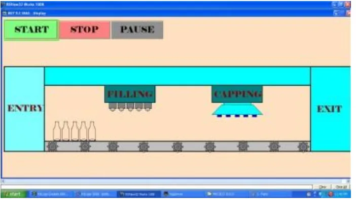
SCADA DESIGN
Fig 49:EMPTY BOTTLES RUNNING
Fig 50:BOTTLES FILLING
Fig 52: CAPPING SECTION
Fig 53:SET OF BOTTLES RUNNING TOWARDS EXIT
This paper has suggested the application of fully automated untouched plc controlled filling and capping operation of a bottling plant. The system works in high speed of production with very much accuracy and precision. This system meets the market demand with a few mechanical effort. The system has been proved working without wastage or spill out of the liquid. It is true that for small scale industries the installation cost of PLC is very much high but it has many advantages which overcomes the instllation cost. In this paper it is suggested how a set of bottle can be filled and capped at the same time. The other additional feature of this paper, here it is explained the SCADA design also. By using the SCADA the whole process can be monitored from a single control room only and necessary steps can be taken in case of emergency.