Jurusan Teknik Informatika, Fakultas Teknologi Industri – Universitas Kristen Petra
GENERATED PICTURE
Budi Hartanto, Silvia Rosalina
Informatic Engineering Department, University of Surabaya e-mail: [email protected]
ABSTRACT: Original ray tracing method can be used to create picture of objects that are very similar to photographic. However for simplicity, the method mimics a pinhole camera in its model. In pinhole camera all objects visualized in the image generated will be seen sharp. In some cases, this kind of image is acceptable but in other cases it is not. For example, in the movie industry, sometimes it is preferable to get the image that can be focused to a certain object and not to all objects. This effect occurs due to the usage of a lens in a camera. In order to get the same effect to the real camera, then it is necessary to modify the original ray tracing method to use lens in its model. The research performed here has successfully simulating the effect of lens in camera. Therefore only objects that are placed in the lens focus will be seen sharp while the others will become blurry.
Keywords: ray tracing, pinhole camera, lens, camera.
INTRODUCTION
Creating a visualization of an object can be done via ray tracing. The resulting picture can be considered good due to its similarity to the picture of object generated from photographic process [1]. However, most ray tracing method used a pinhole camera in its model. A pinhole camera is the simplest camera model ever built. To make a pinhole camera, a closed hollow box can be filled with a film on one side and a tiny hole can be made on its opposite side.
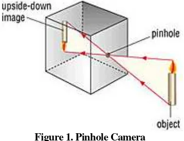
Taking a picture using the pinhole camera can be performed by opening the tiny hole for a certain amount of time, to let the rays burn the film. Since the hole is very small, only limited rays can enter the box at a time. As a result, the rays emanating from the environment in front of the hole will be captured in the film. Due to this limited number of rays, all objects captured in the film will be seen sharp. Figure 1 shows a model of a pinhole camera. The image captured in the camera will be up sided down to the original objects.
Figure 1. Pinhole Camera
In the pinhole camera, the film needs to be exposed for a certain amount of time while the camera and the objects have to be kept steady. Failure in doing this will make the image appears blurry. In some cases, it could be difficult to keep the camera or the objects steady for a certain amount of time. Therefore it is necessary to get the film exposed as soon as possible without having over exposed.
Having a bigger hole in the camera will make the film need to be exposed in a very short time. However since the rays coming to the film will not be convergent then the image generated in the film will become blurry as well. To make the rays convergent, one can put a bifocal lens in front of the camera hole. By using the bifocal lens, not all objects will appear sharp in the film. Only objects that are positioned in the lens focus will appear sharp, while objects in the other position will appear blurry. In some cases, this effect is desirable since the main object can be set focus while the others are not.
to make a modification to the method to get the effect as if the pictures are taken from the real camera. A lens will be set in the ray tracing method to replace existence of the pinhole.
RAY TRACING WITH PINHOLE CAMERA
Ray tracing with a pinhole camera is a common method used to generate a realistic images. The image of the objects can be generated by casting a bunch of rays from a certain point (the pinhole in the camera) to the objects. These rays will be traced to find its intersection to the object. If it is found, then the intensity of light in the intersection point is calculated to be applied to the pixel location, otherwise the color of the background is applied. The intensity of light in the intersection point is calculated using the Lambert Law [2, 3].
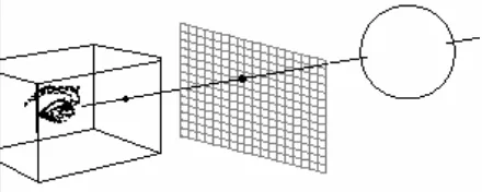
For an example, consider the object to be drawn is a sphere such as shown in figure 2. To avoid the image to be generated up sided down, in this simulation, the film is simply placed in front of the camera. When the ray intersects the sphere then there will be any points that are shared between the ray and the sphere. Therefore finding the intersection can be found by substituting the ray equation to the sphere equation. If the combined equation is resolvable then the ray is really hit the sphere, otherwise no intersection occurs.
Figure 2. Configuration of a Pinhole Camera
The first task to be performed in a pinhole camera is finding the rays that will be cast from the camera. To find the rays it is necessary to set up some parameters such as (see figure 3 and 4):
•The eye position
•The distance of the eye to the film (N)
•Vertical field of view of the viewer (θ)
•Aspect ratio of the film (r)
•Position of the objects that will be seen and the up direction of the camera
The ray will be cast from each sample point in the film. The number of the sample points to be taken can be correlated to the number of pixels in the monitor screen. Their relation can be defined by (see figure 4):
H = N. tan (θ/2) (1)
W = r. H (2)
FilmHeight = 2.H (from -H to H) (3) FilmWidth = 2.W (from -W to W).. (4) ScreenWidth = nCols (0 to nCols-1)
ScreenHeight = nRows (0 to nRows-1)
Figure 3. Vector UVN That Build up The Camera
Using linear equation (5)
Sx = A.x + B
Sy = C.y + D
we can find out that:
uc = -W + W. 2.c/nCols (6)
vr = -H + H. 2.r/nRows (7)
where:
c = horizontal position of the pixel in the screen r = vertical position of the pixel in the screen uc = horizontal position of the sample point in film,
related to the horizontal position of the pixel in the screen
vr = vertical position of the sample point in the
film, related to the vertical position of the pixel in the screen.
Figure 4. Position of a Sample Point in The Film
Therefore the direction of the ray from the eye to each sample point can be determined as:
dir = -N.n + uc.u + vr.v (8)
since the general ray equation is:
r(t) = start + dir.t (9)
then:
RAY TRACING MODIFICATION: CAMERA WITH LENS
Basically lens in a camera is just a curved piece of glass (or plastic) used to focus light that entering the camera. Since there are a lot of light beams entering the camera, then some objects will appear blurry if the objects position are not situated in the lens focus (see figure 5). This blurry image occurs from the contribution of some light beams that coming from different objects. On contrary, when the objects are in focus, all the light beams will come from the same objects. Therefore the image of objects will look sharp [4].
Figure 5. Only Objects in The Lens Focus Will Appear Sharp (Courtesy of Howstuff-works)
Using this characteristic, a producer of a movie can give a focus to a certain actor while make the others blurry. A smaller size of lens will make lots of object come to focus. This is the lens that usually be used in an automatic camera for amateur photo-grapher. If the lens is too small then the camera will become similar to a pinhole camera.
In order to simulate a camera in a ray tracing method, then it is necessary to rebuild the model used. Figure 6 shows the new model of the ray tracing method. Several rays will be cast from each sample point in the film through the lens. Each ray will be traced to get its intersection with any object. When an intersection occurs, the intensity of light at the intersection point should be calculated. The intensity of light yielded by this ray should be averaged with the intensity yielded by the other rays to become a single intensity of light for the sample point. When the object is in focus, all the intensity yielded by all rays will be the same. That is why the picture of the object will appear sharp. The opposite condition will happen when the object is not in focus.
Figure 6. Ray tracing with lens
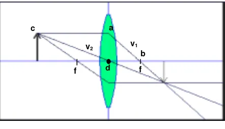
Since the rays cast to the world may not have the same direction as the rays cast from the sample point on the film, then it is necessary to find the real direction of the rays cast to the world. The direction of these rays can be found by using the properties of the three special rays that passing the lens [5, 6]. These three special rays are (see figure 7):
1. A ray entering the lens parallel to the axis will pass the right focal point
2. A ray passing through the center of the lens (at the axis) will not have a direction change
3. A ray exiting the lens parallel to the axis is coming from the ray that has a direction to the left focal point
Figure 7. Three Special Rays Passing The Lens
The direction of the rays casting out from the lens can be found by firstly finding the intersection points of two special rays. If the special rays used are the first and the second one, then we can find that:
Ray 1: a+v1.t1 (10)
Ray 2: c+v2.t2 (11)
where:
a = starting point of ray 1
v1 = direction of the ray 1
t1 = time required by ray 1 to travel to a certain point
c = starting point of ray 2
v2 = direction of the ray 2
t2 = time required by ray 2 to travel to a certain point
c a
b
d v1 v2
At the intersection point: point for all positions involved in the equation, then the equation 12 can be expanded as:
1 2 From equation 13, we can find that:
(
d
x+
u
c)
−
u
c.
t
1=
(
d
x+
u
c)
−
u
c.
t
2The intersection point then can be found by substituting equation 14 to equation 10 or 11. This intersection point can be used to find another direction of rays cast from the sample points on the lens. Therefore the ray equation from each sample point on the lens will become (see equation 9):
start = sample point on the lens (15) dir = intersection point – sample point (16)
This new equation of the ray can be substituted to the objects equation as performed in the original ray tracing method to find the intersection point of the ray to the object. When the intersection takes place a Lambert law can be applied to find the intensity of the light at the intersection point. Unlike ray tracing with pinhole camera that only get a single intensity for a point in the film, ray tracing with lens on the camera will obtain more than one intensity for a point in the film. All of these intensities must be averaged to get the final intensity that should be put on the film. When the objects are not in focus, the intensities obtained for a point in the film will be dissimilar. This is where the blurring effect of the objects comes from.
The overall process of simulating the camera lens in ray tracing can be seen in the following flowchart:
IMPLEMENTATION RESULT
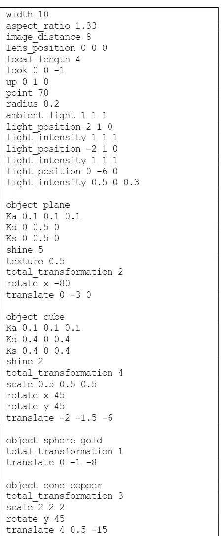
Program 1. Text file required to generate picture such as shown in figure 9a
width 10
aspect_ratio 1.33 image_distance 8 lens_position 0 0 0 focal_length 4 look 0 0 -1 up 0 1 0 point 70 radius 0.2
ambient_light 1 1 1 light_position 2 1 0 light_intensity 1 1 1 light_position -2 1 0 light_intensity 1 1 1 light_position 0 -6 0 light_intensity 0.5 0 0.3
object plane
For comparison, figure 8 shows the image generated by pinhole camera. In the picture, it can be seen that all objects will appear sharp. This image can be generated by creating a new application that using a pinhole camera, or by the same application with a very small lens radius. The second method is used for generating figure 8. The image in figure 8 is creating
by the same keywords and values shown in program 1, but with the lens radius 0.05.
Figure 8. Image Generated by Pinhole Camera
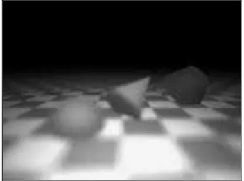
The effect of applying lens for the ray tracing model can be seen in figure 9 to 11. Different lens radius is used for generating picture in figure 9. Figure 9a is created using small lens radius (0.2), and figure 9b by a bigger one (0.4). Small lens radius will make objects in various distance look sharp, while bigger lens radius will make objects that are placed in lens focus only that look sharp. Smaller lens focus will make all rays cast to the similar position. Therefore all the intensity of light yielded from the rays will be similar. In the end, the average of these light intensity will not be too much different from the one generated by a single ray only. As a result, objects in various distance will look sharp.
Figure 10 shows the effect of changing the focal length of the lens. When the focal length is changed, the objects that will be seen sharp will be different, depending on their distance to the camera. Figure 10a shows a cylinder that is in focus (focal length = 5), while the object that is in focus in figure 10b is a box (focal length = 6). Two or more objects that reside in the same focal length will all be seen sharp. Therefore if we want to give focus to a certain object only, then we have to separate the object position from the other. When each object resides in different focal length then it is possible to give focus to a certain object only.
(a) More objects have a sharp image for a camera with smaller lens
(b) Less objects have a sharp image for a camera with bigger lens radius
Figure 9. The Effect of Changing The Lens Radius
(a) Focus on cylinder
(b) Focus on the box
Figure 10. The Effect of Changing The Lens Focus
(a) The Camera position is far from the object
(b) The camera position is near the object
Figure 11. The Effect of Changing The Distance of The Camera to The Objects
CONCLUSION
Unlike ray tracing with pinhole camera model, ray tracing with lens in its model will make the image generated by the method will look sharp only in the area that come to focus only. Moreover, the model can demonstrate some other lens effects as well.
This research shows that the modification of the camera model used in the ray tracing method, from a simply pinhole camera to a camera with lens can expand the variety of picture generated by computer. Therefore one can have more options in getting a computer generated picture. For a bigger scenario, this method can be applied to a movie industry to generate a picture that looks similar as the one taken from a real camera.
REFERENCES
1. Bouville, K.B. (Ed), Photorealism in
Com-puter Graphics, Springer-Verlag, 1992.
2. Buss S.R, 3D Computer Graphics: A
Mathe-matical Introduction with OpenGL. Cambrige
3. Shirley, P, Realistic Ray Tracing. A.K. Peter Ltd, United States of America, 2003.
4. Haris, T, How Camera Works, Taken from http://www.howstuffworks.com/, 2001.
5. Freeman, M; Hull C. Optics, Butterworth Heinemann, United Kingdom, 2003.
6. Smith, G, The Eye and Visual Optical
Instru-ments, Cambridge University Press, United