D A T A M A NA G E M E NT F R A M E W O R K O F D R ONE -B A S E D 3D M O D E L
K orea Institute of C ivil E ngineering and B uilding T echnology, IC T C onvergence and Integration Institute, 10223 Goyang-si,
Gyeonggi-do, R epublic of K orea - (ckim, hsmoon, wslee)@ kict.re.kr
C ommission V I , W G I V /1
K E Y W OR D S : 3D Model, 3D R econstruction, D isaster, D rone, T opography, Unmanned A erial V ehicle (UA V )
A B S T R A C T :
T o rescue peoples in the disaster site in time, information acquisition of current feature of collapsed buildings and terrain is quite
important for disaster site rescue manager. B ased on information about disaster site, they can accurately plan the rescue process and remove collapsed buildings or other facilities. However, due to the harsh condition of disaster areas, rapid and accurate acquisition
of disaster site information is not an easy task. T here are possibilities of further damages in the collapse and there are also difficulties
in acquiring information about current disaster situation due to large disaster site and limited rescue resources. T o overcome these
circumstances of disaster sites, an unmanned aerial vehicle, commonly known as a drone is used to rapidly and effectively acquire
current image data of the large disaster areas. T hen, the procedure of drone-based 3D model reconstruction visualization function of
developed system is presented.
acquisition of current feature of collapsed buildings and terrain
is quite important for disaster site rescue manager. B ased on
information about disaster site, they can accurately plan the rescue process and remove collapsed buildings or other
facilities. However, due to the harsh condition of disaster areas,
rapid and accurate acquisition of disaster site information is not
an easy task. T here are possibilities of further damages in the
collapse and there are also difficulties in acquiring information
about current disaster situation due to large disaster site and limited rescue resources.
T he advent of unmanned aerial vehicle, coupled with
state-of-the-art technologies such as spatial information technology,
materials of UA V and rechargeable batteries, provide engineers
with unprecedented opportunities to overcome the current
processes of site management. F irst and second challenge is difficulties in accessing disaster sites and difficulties in
acquiring information about disaster sites, respectively. B ecause
of the risks of additional collapse of the building by other
equipment or people who walk over the ruins, it is not easy task
to access the location where people are buried under the ruins.
T hird and fourth challenge in the disaster area is the difficulties
in rapid acquisition of buried people location and difficulties in in acquiring life and death information about buried people.
D ue to harsh conditions of disaster areas, understanding of
regional and geographic information is critical issue for disaster
managers. However, because of difficulties in acquiring the
geographical information of the disaster sites such as large
disaster sites and limited capability of rescue workers, comprehensive site investigation of current location of survivors
buried under the remains of the building is not an easy task for additional facilities for monitoring solar panels and modules to
manage solar farms. L iu et al. (2015) developed B IM (B uilding
Information Model)-based progress monitoring framework
using the camera-equipped drone. Z hang and E laksher ( 2012)
developed a drone-based imaging system for 3D measurement
of unpaved road surface distresses.
1.3 R esear ch O bj ectives
T he objective of this study is to develop data management framework of drone-based 3D model reconstruction of disaster
site. T his paper starts with brief description of system
architecture. S econd, procedure of drone-based 3D model
reconstruction is discussed. T hen, visualization function of
developed system is presented. L astly, research contributions
and recommendations are summarized.
2. S Y S T E M F R A M E W OR K
2.1 S ystem A r chitectur e
T he developed system is consisting of four subsystem: drone
module, depth map generation module, 3D viewer module, and
volume analysis module (K im et al. 2015). T he drone module is equipped with various sensors and stereo-vision camera. T he
function of this module is to acquire image data of the disaster
The International Archives of the Photogrammetry, Remote Sensing and Spatial Information Sciences, Volume XLI-B4, 2016 XXIII ISPRS Congress, 12–19 July 2016, Prague, Czech Republic
This contribution has been peer-reviewed.
site. T he depth map generation module develop depth map of
the disaster site. T he 3D viewer module visualize the 3D terrain
model and 3D collapsed building model. L astly, the volume
analysis module calculate volume of the 3D terrain model and
3D collapsed building model.
2.2 D r one H ar dwar e
T he stereo-vision equipped drone has GPS (Global Positioning
S ystems) module, A HR S ( A ttitude and Heading R eference S ystem) and IMU (Inertial Navigation S ystem) module to locate
the current position and movement of the vehicle. T o install the
stereo-vision camera module D J I R onin Gimbal is used and two
lithium-ion cell (16,000mA h) are installed to provide the power
to the drone. F or the stereo vision camera module, two Point
Grey cameras ( 1600× 1200, 59F PS ) are installed. T his module
also has function of wireless data transfer ( W ireless L ocal A rea
Network) to receive the saved image data of the disaster site and
log data of the drone.
2.3 3D M odel R econstr uction Pr ocesses
T he first step of the drone-based 3D model reconstruction
processes is to acquire disaster site image data from the stereo-vision camera equipped drone. In this process, stereo image
data and location information of the drone are automatically
saved on the server of the drone module. T hen, depth map of
the disaster site is developed to generate 3D point cloud model
of the disaster site. Next, using triangulated irregular network
algorithm, the point cloud data of the disaster site is converted into the 3D model of the disaster site. T he detailed processes of
the system are presented in the next section.
3. D R ONE -B A SE D 3D M O D E L R E C ONS T R UC T I ON OF
D I S A S T E R S I T E S
3.1 3D M odel G ener ation
Prior to generate the depth map of the disaster site, log file from
drone and image data from the stereo-vision camera, in other
words image data from the left side camera and image data from
the right side camera are required. T hen the epipolar line
matching process is conducted to generate the depth map of the
disaster site ( F igure 1). In this process, feature point extraction is conducted to adjust image difference between image data
from the left side camera and right side camera(F igure 2).
F igure 1. E pipolar Matrix C alculation
A fter depth map generation from the stereo image matching
process, the depth map is converted into the point cloud data
(F igure 3) . L astly the 3D model of the disaster site is generated
(F igure 4). T o generate the 3D coordination of 3D model of the
disaster site, the information about the image data and location
data such as focal length, pixel size and base line between two
cameras are utilized.
F igure 2. F eature Point E xtraction between Image D ata from
L eft S ide and R ight S ide of the S tereo-vision C amera
dd d
F igure 3. D epth Map (L eft) and 3D Point C loud Model ( R ight) of the D isaster S ite
d
F igure 4. 3D Model of the D isaster S ite
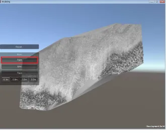
3.2 3D M odel V iewer
T o effectively visualize the 3D model of the disaster site, the 3D
model viewer is developed using Unity engine.
F igure 5. 3D Model V iewer
The International Archives of the Photogrammetry, Remote Sensing and Spatial Information Sciences, Volume XLI-B4, 2016 XXIII ISPRS Congress, 12–19 July 2016, Prague, Czech Republic
This contribution has been peer-reviewed.
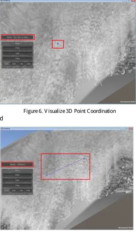
T he 3D model viewer have function of providing information of
3D point coordination, calculation of distance between two
points, and calculation of selected area.
F igure 6. V isualize 3D Point C oordination
d
F igure 7. Measurement of D istance between T wo Points
d
F igure 8. C alculation of S elected A rea
In the 3D point coordination information function, the X , Y , Z
coordination of the selected point is presented on the result
window, when user click the point button on the menu and then
click the point. T o measure the distance between two points,
click the line button on the menu and then click the two points
on the disaster site 3D model. T he calculation result of the distance measurement is presented on the screen. L astly, to
calculate the area of the selected region, click the face button on
the menu and then the user can printed grid on the 3D model of
the disaster site. Next, click the points on the grid and made the
closed polygon. T he value of the selected region’s area is
calculated and presented on the screen.
4. C ONC L US I O NS A ND R E C O M E ND A T I O NS
T his study presented the data management framework of
drone-based 3D model reconstruction of disaster site. F irst, this paper
presented the system framework of system architecture and
drone system. T hen, the processes of the developing depth map
and point cloud model of the disaster site are described. L astly
the 3D model generation and the functions of the 3D model
viewer are presented. F or the future study, the field tests should be required to confirm the accuracy and applicability of the
developed system.
A C K NO W L E D G E M E NT S
T his work was supported by National R esearch F oundation of
K orea grant funded by the K orean Government (NR F
-2014R 1A 1A 2056217) and “D evelopment of 3D model
reconstruction technology of disaster area and location detection technology of survivors buried under the remains of
the building” project funded by K orea Institute of C ivil
E ngineering and B uilding T echnology (K IC T ).
R E F E R E NC E S
L iu, P., C hen, A . Y ., Huang, Y .-N., Han, J .-Y ., L ai, J .-S ., K ang
S .-C ., W u, T .-H., W en, M.-C ., and T sai M.-H., 2014, A R eview
of R otorcraft Unmanned A erial V ehicle (UA V ) D evelopments
and A pplications in C ivil E ngineering, Smart Structures and
Systems. 13(6), pp. 1065-1094.
S iebert, S . and T eizer, J ., 2014, Mobile 3D mapping for
surveying earthwork projects using an Unmanned A erial
V ehicle (UA V ) system, Automation in C onstruction, 41, pp.
1-14.
S kycatch Inc. 2015. T rack Y our S olar F arms R emotely and
A utonomously, retrieved S eptember 1, 2015, from
https://www.skycatch.com/solar.html.
Z hang C . and E laksher A . 2012. A n Unmanned A erial V
ehicle-B ased Imaging S ystem for 3D Measurement of Unpaved R oad
S urface D istresses. C omputer-Aided C ivil and Infrastructure
E ngineering, 27(2), pp. 118-129.
The International Archives of the Photogrammetry, Remote Sensing and Spatial Information Sciences, Volume XLI-B4, 2016 XXIII ISPRS Congress, 12–19 July 2016, Prague, Czech Republic
This contribution has been peer-reviewed.