3D
PRINTER
MAPPING
OF
MRI
COIL
FIELDS
FOR
FETAL
IMAGING
Alexander
Vavoulas*,
Nicholas
Vaiopoulos*,
Panagiotis
Karageorgos*,
Christos
G.
Xanthis*,
Harilaos
G.
Sandalidis*
and
Anthony
H.
Aletras
**
*
University
of
Thessaly,
Dept.
of
Computer
Science
and
Biomedical
Informatics,
Lamia,
Greece
**Aristotle
University
of
Thessaloniki,
Medical
School,
Lab
of
Medical
Informatics,
Greece
[email protected];
[email protected];
[email protected];
[email protected];
[email protected];
[email protected]
Introduction
The development of radiofrequency (RF) coils used in fetal and neonatal imaging demands exhaustive magnetic field measurements via a clinical MRI scanner, which is not always possible or available. For this purpose, a novel experimental setup for the characterization of the 3D magnetic field of RF coils used in MRI scanning is proposed in this study.
Results
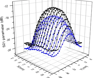
Fig. 2 shows the measured S21 parameter for z equal to 1.5 and 3cm. The maximum value was measured only when the coils were concentric, which is consistent with the plot of the analytical expression shown in Fig. 3. Note that the complete calculation of the magnetic field of a single loop over a plane coil invokes Bessel functions and elliptical integrals.
References
1. D. C. Smith, (1999), “Signal and noise measurement techniques using magnetic field probes”, IEEE International
Symposium on EMC, pp. 559‐563.
Methods
A specially configured 3D printer, which was driving a shielded circular loop (“sniffer”) coil in cartesian coordinates, was used as a magnetic field measuring device. The measured RF coil was placed stationary in the inactive heating bed of the 3D printer and could be either a surface coil or a volume coil used in several MRI applications. It must be noted that the shielded sniffer coil was favored over an unshielded one so as to permit electric field shielding of the center conductor [1]. A two port network analyzer in the setup was connected to the two coils and was used to measure the scattering parameter S21, which can be converted into power ratio. The measured RF coil was connected to the transmit port whereas the sniffer coil to the receive port of the network analyzer. The S21 parameter value was collected at the resonance frequency of the measured
RF coil, given by the Larmor equation f0 = γB0 (γ represents the
gyromagnetic ratio and B0was the static magnetic field strength of the MRI
scanner). The movement of the sniffer coil in cartesian coordinates was controlled by the 3D printer’s embeded microcontroller software and was
programmed in G‐code. Data collection and processing was performed with
a desktop computer which was connected with both the network analyzer and the 3D printer. against XY coordinates for z=1.5cm.
In order to evaluate the experimental setup a set of measurements was collected from a single loop RF coil with 5cm diameter and a shielded sniffer coil with 2cm diameter. The separation of two coils along the z axis was set at 1.5cm and the scanning took place over a XY
plane with dimensions (813)cm. The same procedure repeated for z=3cm. The scanning step in XY coordinates was 5mm. The single loop
RF coil inductor was split with two variable capacitors and the resonance frequency was set at 42MHz. The overall scanning time was about 1 hour.
Figure 1. Experimental setup
Acknowledgement