INTEGRATED STRATEGIES FOR THE MODELING OF VERY LARGE, COMPLEX
ARCHITECTURE.
Francesco Fassi*, Cristiana Achille, Fiorella Gaudio, Luigi Fregonese
Politecnico di Milano (francesco.fassi, cristiana.achille, fiorella.gaudio, luigi.fregonese)@polimi.it
Commission V
KEY WORDS: Laser Scanner, image matching, image modeling, complex architecture, cultural heritage
ABSTRACT:
The paper would like to present a research job conducted in cooperation with the Veneranda Fabbrica of Milan Cathedral to survey and model the main cathedral spire. The job aims to find methods and a typological way to operate to produce an accurate 3D model to support forthcoming restoration works. The paper will concentrate on the description and analysis of problems and difficulties found during the survey processes and solutions chosen to overcome these problems, both in the measuring phase but in particular in the processing one. Future research is also proposed.
1. INTRODUCTION
1.1 The main spire
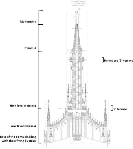
It was built in 1765 by Benedetto Croce, four centuries after building started on the Cathedral. The term "Main Spire" identifies the unitary block overtopping the main vault of the Cathedral. The total height of the spire, including the statue, is about 43 meters and it rises towards the sky reaching about 108.50 meters above the floor of the Duomo (Fassi, Achille, Fregonese, & Monti, 2010).
Figure 1: Some fun pictures of survey moments on the spire. The image shows work conditions and the environment to be
measured.
Figure 2: A diagram of the spire.
Everything is in Candoglia marble and this is the key aspect of the whole work, as described in depth below.
It has different parts, as shown in the figure above: the octagonal base, 9 meters high, rests directly on the lantern and is connected by eight flying buttresses to the side walls, rising from the lantern; the octagonal prismatic pipe, 19.40 meters high, surrounded by eight columns; the spiral staircase leading to the last landing terrace called “Belvedere” rotating between these columns and the central pipe; the finely decorated terminal pyramid 9.77 meters high; the Madonna statue, made of gilded copper (about 5 meters high) universally known as the “Madonnina”. It is a really complex object rich in decorations, statues, terraces, narrow places, columns, arcs and flying buttresses. At present, the spire is caged in huge scaffolding designed ad hoc to be able to proceed with restoration.
1.2 The main goals
This job wanted to create a detailed 3D model of the spire. To be used for professional purposes both to plan the restoration and for routine works on site. In this context the model needed to be "accurate", "complete" "easy to manage" and "final". The word accurate means it should be a "real based model" sufficiently accurate for extraction of metrical information on a scale of 1:20 - 1:50. Some parts were also, and additionally, modeled supporting the real scale 1:1.
The model should be complete; it should contain structural information but also show the spire’s huge, complex, decorative apparatus.
It should be "simple to manage". This aspect can be considered in different ways. First of all, the modeling phase should be relatively easy during both initial model construction from data measured and also in later change and upgrading stages. The 3D model should be available for different kinds of operators to use and modify in different ways and for different purposes (design, planning, storing information, visualization...). All these operators are not normally proficient in using 3D software which is typically complex and requires skilled operators. In this context the "working software" choice should fall on an application that allows us to reconstruct the object’s geometry from different kinds of surveys with the desired accuracy and should be relatively simple to use and learn. The second aspect is that the object to be modeled is a huge, complex structure. Consequently, the digital model will be very complex too and should be structured and segmented to be easily and quickly visualized and inspected.
It should be "final" meaning that the model should not only be the "real, exact geometric image" of the object, but also the robust base on which it is possible to study and simulate future modifications. For this reason, it must be easily upgradeable to store and report later structural and geometrical changes. Damage and deterioration will not be modeled: the survey purpose is the structure’s geometric shape. Damage information will be added separately in another way, as described at the end of the paper.
The main goals were: i) to extract all kind of 2D information such as classical sections, plans and vertical profiles; ii) to extract 3D information, like volumes, weights, that can be useful and usable during renovation, iii) to create a kind of 3D catalogue of all marble blocks, to be visualized, measured and tabulated with all necessary additional information also during yard operations and iv) to build detailed 3D models of the ornaments for a sort of reverse engineering of the artistic parts.
2. THE MAIN PROBLEMS
The main problems met when surveying and modeling a complex object like this can be divided into two categories. First, we found a lot of operational problems due to narrow spaces, construction in the meantime of the huge scaffolding obviously limiting survey operations and availability times. Not least, the weather that influenced the measuring phases a lot. Another aspect was managing a huge quantity of acquired and processed data. What’s more important here were procedural problems caused by the marble surface and narrow spaces. Georeferencing all data together in a general reference system, merging different datasets and texturing problems is also described.
2.1 Marble surfaces: from laser scanner to photogrammetric approach.
The natural choice is to use a laser scanner solution. Theoretically, it is the right strategy for surveying the spire globally. The original idea was, in fact, to perform a complete high resolution scan of the spire and extract all the information segmenting the huge point cloud into different sub-objects based on position and role inside the object (structural or ornamental). The modeling phase was planned dividing the object into "linear based objects" (normally the structural ones) and "surface based objects" (normally the decorative apparatus) performing two different modeling strategies. In the first case, simplifying the structure by extracting edges, sections, plans, profiles and building a model using classical Boolean operation procedures to build the 3D model. In the second case, the procedure could be to build a meshed model of decorations, eventually upgrading the original cloud with more detailed dedicated scans.
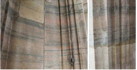
Figure 3: Typical Candoglia marble blocks on the spire.
This kind of strategy presents serious problems due to the spire’s construction material which, as described above, is Candoglia marble. It has a calcitic marble composition, pale pink or gray with black veins, medium grain, compact; it is part of small lenses arranged vertically in the formation of the dioritic-kinzigitica zone of Ivrea-Verbano The quarries are located upstream of Candoglia (Verbania). Maybe used in Roman times, they are currently operating the main quarry, in the gallery, which provides excellent quality material and Cornwall, a surface mining quarry which provides a lot of veined material. Since 1387, according to a privilege granted by Gian Galeazzo Visconti, the excavated material has been reserved for work on Milan cathedral where it was used for coating, decorations and sculptures. Everything in the Milan cathedral, thus the main spire, is marble. All marble blocks are rough with pollution and weather damage. In particular the small spires enclosing the main spire are subject to erosion due to corrosion, differential degradation, fractures and cracks that could prelude to further separation. The central pipe, including balconies and parts of the statues and much of the flat wall surface inside the stairs, is mainly affected by black crust damage (on statues and carved decorations), by crust residues or artificial patinas on wall surfaces or sculpted reliefs. The deterioration types described were studied thoroughly for past restoration works on the facade but can also easily be recognized here. (Dalaidi B., 2004) For this reason a lot of spire parts need continuous replacement of damaged items rebuilt by patient artists and ornatists in the Veneranda Fabbrica’s two marble laboratories.
The marble surface does not enable good, full use of the laser scanner. In fact, scans present artifacts that cannot be corrected or eliminated or simply left aside. Huge blunders in surface International Archives of the Photogrammetry, Remote Sensing and Spatial Information Sciences, Volume XXXVIII-5/W16, 2011
Figure 4: Degradation of marble blocks. In the image above the presence of black crust and artificial patinas. Candoglia marble has a significant pyrite content that may be sporadic or even have large aggregates of crystals. There are also rare grains of
magnetite. The presence of metal minerals determines, unfortunately, a lack of durability, with the consequent need for
damaged parts to be replaced continuous. Images below show an important detachment of material and deterioration of the old
iron anchorage.
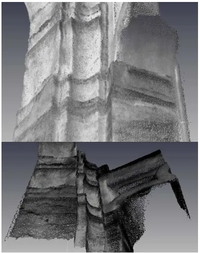
Figure 5: Examples of low quality point scan due to the marble surface inside the spire’s helicoidal staircase.
interpolation due to laser light penetration do not enable us to reconstruct the whole geometry accurately and guarantee the final precision required. We had a phase shift scanner (Leica HDS6000) at our disposal, tested in our laboratories to study the entity of the artifact on scans based on distance, laser incidence angle and laser power. Artifacts and scan errors
become more evident using the laser scanner near the surface and this is the main problem due to narrow spire spaces. A better solution, on paper, would to use a time-of-flight scanner with less scan distortion, compared to the one used, when the distance between laser and object is longer than 3 meters; but, with shorter distance, the differences between the two instrumentation types is insignificant. Moreover due the huge size of the spire and limited operating space, the choice was to use the HDS6000 scanner, faster and smaller than the Riegl that we had at our disposal1
The decision was to perform all scans even if results were not so accurate and, at times, really not usable for modeling. However, the point cloud model was useful for creating a rough 3D model quickly, to let us explore the spire, catch hidden spaces, extract fast profiles and take fast measurements. It will also be useful in future modeling to test global georeferencing and scale and merge the photogrammetric modeled part together.
.
2.2 Solutions: the main workflow of the modeling phases.
It is therefore evident how the laser scanner cannot be used alone to measure the spire accurately. The alternative strategy is to use photogrammetry ensuring accurate 3D geometry extraction both for "linear objects" (walls, columns, pillars...) using a image modeling approach and for "surface objects" (statue and decorations...) using image matching.
The basic idea is to divide the spire into its macro zones: dome cladding, low level stair case, first Terrace, high level staircase, second terrace (Belvedere), the final pyramid and the Madonnina. Each macro zone, except the Madonnina and the stair cases, treated as single objects, is subdivided into eight parts corresponding to the eight cloves making up the spire structurally.
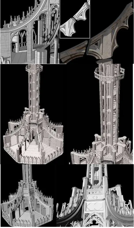
Figure 6: Summary diagram of the subdivision of the spire to compute a structured modeling process. In green the elements
modelled photogrammetrically using an image modelling approach. In violet those modelled with a laser scanner and pink
the parts reconstructed with a image matching process.
The first step
1
Note that the Riegl instruments could not be used in 60% of the spire because it is too big for those spaces.
was to extract a "rough simplified model" of the macro areas. It was mainly done using a photogrammetric "image modeling" approach. The choice to model such big areas totally, and not subdivide them at this phase of the job, might International Archives of the Photogrammetry, Remote Sensing and Spatial Information Sciences, Volume XXXVIII-5/W16, 2011
seem risky in particular related to the large number of images to be oriented at the same time and to support a more complicated, hard block adjustment computation. The choice was to build close circular capture geometry around the main spire pipe to get better results in terms of mean accuracy. Dividing the diverse macro areas into mini-blocks is surely an easier job, but it needs more photos, more control point acquisitions, and also means orienting the same photos several times. Moreover, in this process the models, extracted from two contiguous micro-areas, can have topological and connection problems that are really difficult to evaluate and correct in post-processing. On the other hand, processing a unique circular and close photo-block for the entire macro-area spreads the errors over the whole block, offering better mean-accuracy in the end.
Difficulties mostly came from the extremely narrow places and the presence of scaffolding reducing the space even more. For this reason in most cases we were forced to use poor local capture geometry where photos are mainly done in a bottom-up direction and with very low capture angles. This created serious uncertainty in XZ placement of the extracted 3D points. To minimize the problem, a good quantity of topographic control points had to be acquired for better orientation, making stronger blocks and a sufficient number of check points to evaluate final 3D restitution accuracy. Moreover, we used a redundant number of images with resulting inevitable hard, time consuming work to orient the images.
During the job different kinds of digital, fixed focal cameras2 were used. The cameras were calibrated on site simultaneously with the ongoing photogrammetric survey and manually oriented using Photomodeler Scanner.
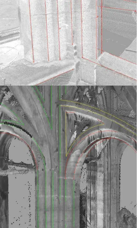
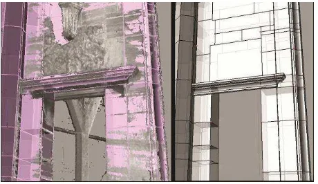
Figure 7: Reconstruction of columns and subdivision into their constructive marble blocks. Block break-lines and corner lines
are extracted photogrammetrically. Model refining and completion is done with support of a laser scan point cloud.
After the orientation stage, the first modeling phase inside the photogrammetric software began. Due to its limited modeling capabilities and the "limited" number of images, we could only extract the primitives characterizing the main, simplest constructive elements. In particular we focused on the extraction of sharp edges, long arcs and divisions among marble blocks. As we needed to speed up and simplify the orientation phase as much as possible, we did not include images taken to reconstruct particulars or small details (like the decorated bases of columns) in the orientation process. For this reason, in many cases rounded and smaller elements could not be modeled due to insufficient information on the photos. The same thing
2
Mainly a Canon 5D mark II with 35mm fixed lens.
happened for rounded surfaces for which you need to collect many pairs or corresponding construction points on the image pairs. That is difficult and extremely time consuming; and consequently it is preferable to postpone refining the model to a later stage.
At the end of this step we operated a first global check of the extracted model using the laser scans to find blunders and gross errors.
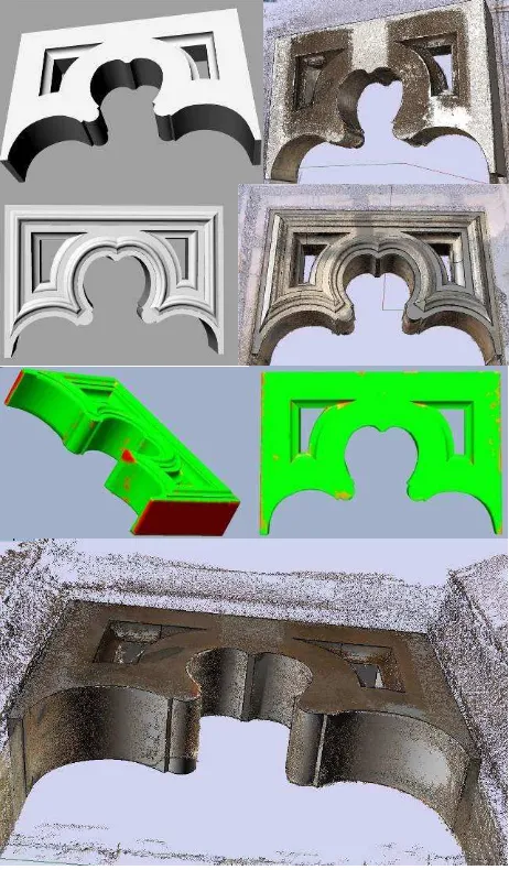
Figure 8: Above: a visual comparison between point cloud and the photogrammetrically extracted primitive. You can see how the column base is not modelled at this point because too rich in
details, difficult to extract and model in photogrammetric software. Below: image showing a quantitative check. In green the line in tolerance (< 15 mm) in yellow the acceptable feature
(circa 15 mm), in red the out of tolerance feature. As appropriate, the model is corrected and refined later in the real modeling phases or corrected in the photogrammetric software
directly.
In the second step all clove models are subdivided into micro areas corresponding to the main structures (columns, flying buttresses, walls, balustrade). The previously extracted primitives are joined together and completed integrating missing data with laser scans, direct measurement3
3
For small details in hidden parts of the spire.
or, as described later, with dedicated photogrammetric survey. International Archives of the Photogrammetry, Remote Sensing and Spatial Information Sciences, Volume XXXVIII-5/W16, 2011
The third step
For some chosen types of marble blocks, the job is improved even further. They will be reconstructed on a greater scale using an "image matching" procedure to get a more detailed, accurate model. This will be done for decorations and statues that can obviously be reconstructed in a simplified way.
is to split the finished models into constructive marble-blocks that are the structure’s "fundamental elementary units". The model is always split using the photogrammetric way, identifying the break-lines between different blocks on images. Eventually, to speed up the process, using the laser scans. In some cases, in particular for decorative parts, this operation is done by manual measurement.
Due to the large number of decorations, we needed a relatively fast acquisition strategy; also for objects that are difficult to reach and measure, because they are suspended outside the spire, partially covered by scaffolding or hidden by the main spire structure.
For these reasons using a scanner (laser or light projection scanner) is difficult. Moreover the job should be done on scaffolding that moves and does not allow stable positioning of this kind of instrumentation. For these reasons the choice was to use the photogrammetric approach here too.
The main problem in this case was the complexity of decoration forcing us to use a large number of images to reconstruct their complete 3D geometry. Use of automatic image orientation procedures was, at this stage, absolutely necessary. In fact, spire decorations are normally not very big (and can be decomposed into sub-parts) but they are complex, rich in undercuts and details. To reconstruct the simplest, smallest ornaments fully, more than 40/50 images had to be used. It was unthinkable manually!
We were testing different applications that let us compute image matching, but also image orientation. We tested the beta version of a Photomodeler scanner 10 for some time, with which you get some good results but only if the capture geometry is not extremely complicated. For the moment we get better, faster results using PMVS2 that do totally automatic image matching of a large number of images previously pre-oriented using Photosynth.
Orientation using Photosynth is fully automatic and does not require image calibration. It can use image-blocks with photos taken by different cameras and using the zoom at the same time. This aspect is quite important in our case in the work environment described. In fact, it is not always easy to reach all decorations and details and use of professional high resolution cameras with calibrated fixed lenses (normally used for the previously described photogrammetric survey) is sometimes difficult to do. Small, more manageable commercial cameras with zoom are, in many cases, the comfortable, winning choice. The automatic orientation process does not always provide good or accurate results. A quality check is needed before continuing the successive modeling phases. Our tests confirmed that a "close spherical capture geometry" around the object, using a lot of images, normally dramatically decreases the possibility of completely wrong reconstruction and provides sufficiently accurate modelling results. More extensive tests are being carried out to quantify maximum accuracy achievable using this method.
The spire has a huge quantity of different kinds of ornaments. These can be divided by characteristics including size, location, wealth of detail and decorative or structural function. We used quite the same operating capture strategy for each type dedicating, on the contrary, differing time and attention during the modeling phase depending on the importance the ornament has inside the structure. Some small ornaments on the balustrade and on minor spires were captured and modelled
virtually only for model completeness and for the spire’s decoration database. For this reason the proposed method Photosynth + PMVS2 (Patch-based Multi-view Stereo Software) was considered optimal because it is fast and sufficiently accurate.
Some others, on the contrary, can be considered structurally important for their static role and because they are supporting elements in the spire structure. These parts are to be modeled accurately and precisely at a 1:1 scale to be reconstructed and substituted inside the structure. They are normally poorly decorated marble blocks and are the simplest object to rebuild. For this reason, the idea is to perform a reverse engineering procedure to rebuild them automatically using a CNC machine. The Veneranda Fabbrica del Duomo is thinking of using the same procedure for more decorated objects and ornaments. This, first of all, to have a complete three-dimensional database of the decoration at a 1:1 scale and also speed up and consequently make the production of ornaments to be replaced more economic. This cannot replace the indispensable manual ability of the artists who normally recreate these parts but can speed up the first phase of boasting the marble decorations.
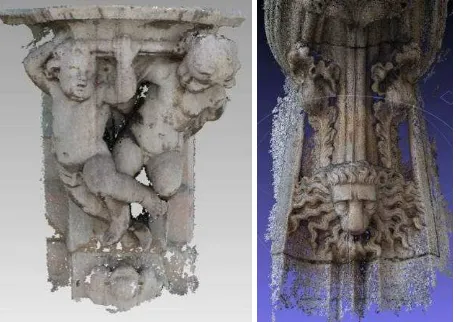
Figure 9: Two point cloud examples extracted by image matching using PMVS2 software. For the decoration on the left 94 images (3200x2134) were used to get a point model of about 1160000 points. For the decoration on the right 40 images were used at the same resolution for a model of about 700000 points.
Generally the strategy followed was to take a large redundant number of photos all around the object taking care to capture each detail shooting from every possible angle (central, from right, from left up and down). This guaranteed full orientation of the image block, a denser matching result and model continuity when the surveyed object could be acquired in toto with single shots (for example the six meter high small spires on the first terrace).
2.3 Georeferencing and merging the subdivision.
A trigonometrical survey was needed to materialize a global reference system and check final model accuracy. A relatively complex control network was established using four rigid measurement rings: one at the height of cathedral roofs, one on dome cladding, one on the first belvedere and one on the last belvedere. All these measurements were computed and adjusted to high precision measurements previously taken inside the central dome for the static control of the whole structure. Geometric measurements were also needed to survey objects that could not be reached otherwise.
Due to the initial photogrammetric rough modeling phase and use of a large number of control points, all the base model structure was georeferenced automatically in the global reference system; consequently the entire modeling process was done directly inside it. Some problems were had with the separately modeled parts, such as those described in the previous paragraph. Parts reconstructed with image matching were to be scaled and merged inside the global model in the right position. Although this may appear to be an easy operation, it has problems and difficulties. First of all, scaling the object can be easy when the object is easy to measure (as in the case of figure 10), but is very difficult or at least inaccurate when the object is complex and it is difficult to find a precise anchor point where you can measure the distance on the object itself and on the corresponding model accurately. The main solution is to model the surveyed object together with a portion of the structure carrying it or add some known object to the scene artificially.
Another problem was to merge the model in the correct position and in the correct way. To insert it in the right position modelling the object considering a part of the surrounding structure can be useful and using, for example, laser scanner data to georeference it. When the laser data has good resolution and quality this can be done automatically. Otherwise it should be done semi automatically or manually with a consequent lost of accuracy. The main problem with this operation is the constructive differences between the two digital models. In particular, because, in these cases, the model to be inserted is more accurate than the global hosting structure that, as described above, is normally simplified. In fact the first one, as in the case of rich decorations or statues, is a detailed, high resolution mesh and the second is a simplified nurbs surface. In this case the nurbs object, or part of it, has to be transformed into mesh and the triangulation should be subdivided to get a comparable resolution to that of the more detailed object. This operation is totally manual, really delicate and time consuming.
2.4 Texturing the model
Another aspect analyzed is texturing the model. This is an important task in this kind of work. The color texture can provide additional information to the model. In particular, in the 3D catalogue, described before the texture of each single marble block, you can describe the objects’ state of health and, in the future, create a historical database of changes caused by time, pollution, restoration. For this, the texture must be applied accurately and possibly automatically. For this reason, an automatic model texturing process, using the previous images oriented in the modeling phase, is being developed.
2.5 Model quality.
As was described at the beginning of the paper, the final model needs to be accurate and comply with a 1:20-1:50 representation scale. For this reason, a model quality check is done at each step. The laser scan point cloud can be used to test global accuracy. In this way, you can find blunders, missing parts or georeferencing mistakes.
Figure 10: The 1:1 model of a statically important object to be rebuilt automatically. The model is done in rhino from the point
cloud extracted from images. The deviation between reconstructed model and original point cloud is checked using
RapidformXO. Green corresponds to the areas where the maximal deviation is 2mm. In the red area, the object shows some damage that is eliminated in the modelling phase. It was
restored virtually!
This can be done visually loading the two models in the same software or, for example, mathematically using the model comparison module of RapidformXO. In this case the deviation between scans, nurbs and reconstructed model can be checked numerically. To do this the nurbs rhino model has to be transformed into mesh (according to the point cloud resolution) to evaluate deviations correctly.
A more detailed test was done locally using the topographic points collected, used previously for photogrammetric purposes or additionally measured to test analysis. For details and big scale objects an accuracy check was done, as described, singly and carefully during the whole process. 1:1 modeled pieces are obviously more accurate than the whole model because they were constructed for an additional different purpose, automatic reconstruction. For this reason, insertion in the model can cause some problems. They will be arranged inside the global model to complete the model and respect continuity and topology at the native model scale even if this means loss of precision. International Archives of the Photogrammetry, Remote Sensing and Spatial Information Sciences, Volume XXXVIII-5/W16, 2011
Figure 11: Example of a complete model of this part with subdivision into its constructive blocks. On the left, the comparison with the point cloud, on the right with check points
collected topographically.
For model quality, you do not just consider the measurement’s quantitative aspect but also the qualitative one. In particular the model must be ready and able to be used for any kind of future purpose.
In this context, the model should have some important requirements common to other modeling fields (i.e. mechanical), but oft not respected in architectonical areas of interest. We use the most restrictive rules typical of prototyping; that means that the model should have correct normal orientation, closed surfaces, and does not have duplicates, overlapping surfaces, discontinuities or bad contours. That means that an accurate continuous model check must be done during the modeling phase itself.
2.6 Managing the model: from creation to use.
The entire model was built at origin using Rhinoceros. The choice was for different reasons. In particular, because it is easier to use than other modeling software. Moreover it is ideal for a "real based modeling process" where reconstruction is done based on accurate measurements coming from different datasets. In fact, with the support of Pointools for Rhino plug-in, letting you visualize and use point clouds in Rhino at high resolution, you can model and check the modeling workflow at any time using both laser scanner and image matched points data. Moreover, for its use and learning simplicity, it is the ideal 3D working environment for external technicians who do not normally have professional modeling skills, who will use, modify and work on the model in the future. (Fassi, Achille, Fregonese, & Monti, 2010)
An operational problem in doing a job like this comes from the fact that multiple, diverse data sets are used and integrated to complete the model. We had many I/O problems importing and exporting data from and to different software environments: loss of scale, loss of georeferencing, loss of model quality.
A final aspect to be analyzed, but not for importance, is managing the model finally. As the previous descriptions make clear, the resulting final model is huge. It is huge for spire size; it is huge for level of detail and for number of modeled parts. At the moment, 70% of the model in Rhino is made up of nurbs surfaces so it is still relatively easy to manage with a powerful workstation. Problems arise when the remaining 30%, or small parts of it, of the meshed triangulated model are integrated. The software crashes or cannot be used for a regular job due to the large amount of information it has to manage. At the moment, the problem has not been resolved. The complete model can
only be visualized completely using PointoolView importing each part separately. It is definitely a good solution for visualization, but the proprietary format of the imported files imposes that the original model be transformed into pod format and this creates some I/O problems.
3. THE MAIN QUESTION: WHAT IS IT FOR?
The model is not intended to be a finished object that, once made and displayed, will no longer be used. The entire job is certainly great training and the chance to test new surveying methods, but does not want to be, as often happens, only one, even exceptional, measuring and modelling exercise. It must be and constitute the base for future action both for immediate restoration operations and for later planned maintenance. To achieve this goal, we have to consider some important aspects. First, use of new software packages that would not suddenly, brutally upset work habits and methods experienced over the years. For this reason we chose a modeling and operative ambient (Rhino) that can easily substitute or join Autocad as default software for the daily practice of the cathedral’s site management and restoration design and maintenance, today still done with a 2D point of view. Secondly, the end user must be accompanied in the arduous transition to the three-dimensional vision and way of working. For this reason, we are working closely with Veneranda Fabbrica technicians, both for scrupulous 3D training , but also to thoroughly understand how the model can be used and answer the main question, "what is it for?". Classical visualization and classical measurement purposes of a three dimensional model like this are, in our opinion, maybe too simplistic and probably not so attractive in order to replace the even more traditional ways of working in 2D. We are convinced that it has additional potential and provides additional information that a 2D representation cannot. For this reason, we are developing a system to manage the large hierarchical sets of three dimensional geometry data and relative linked information easily. The main goal is to create a real 3D database of all spire parts where any kind of geometrical, technical, and visual data is linked together, and can be stored, visualized, modified and queried in a huge, global three-dimensional information system. This goal is achieved by implementing two different applications, a back-office integrated into the three dimensional modeling software (Rhino) and a front-office deployed on a web platform. Back-office allows technical users to add rich information to geometrical data and store it in a relational database. The front-office part permits us to search in the dataset and visualize results, three dimensional elements and information (eventually adding it) directly in any HTML5 capable web browser. The back-office implementation is being developed in the Microsoft .Net environment with the use of RhinoCommon (new Rhino5.0's cross platform SDK) and OpenNurbs, that is McNeels first open source code initiative, providing access to the native Rhino 3DM file format without restriction or royalties. This allows you to work in the modeling environment (Rhino) directly. The front-office implementation is being made through the X3DOM framework, a DOM-based HTML5/X3D integration model, and ASP.net technologies. This double joint application is expected to use the same database during the designing phases (back-office) and also on site during operations on the spire (front office). The possibility to consult the 3D model and view, modify or add correlated information to the model online can be very useful during on-site operations substituting classical paper&pen procedures. International Archives of the Photogrammetry, Remote Sensing and Spatial Information Sciences, Volume XXXVIII-5/W16, 2011
Figure 12: At the end of the modeling phase the global model is made up of six macro-blocks subdivided into micro-bocks corresponding to the clearly identifiable and/or decorative building parts. Each of these, is in turn composed of its
elementary constructive elements.
4. CONCLUSION
The paper provides a fast synthesis of the survey’s modeling workflow and modeling of Milan Cathedral’s main spire. The explanation gives us the opportunity to suggest a way to survey and model complex architecture integrating different methodologies. In particular, presenting problems and possible solutions found during the job both for operating difficulties inside a very intricate environment and for experimentation and integration of different new methodologies in a complex test field like this.
An interesting aspect of this work is that, over the years, technologies and methodologies have changed and been upgraded enormously. We have the chance as the job continues (still in progress) to experiment and test the different steps of this development in survey and data processing methods. In this context today, it could be possible to proceed in ways that differ to last year. In particular, the main improvements can be found in automated orientation and matching and in the possibility to manage a large number of images in the process. For example, difficulties and, consequently, time consuming hard manual
orientation work could be replaced by well worked automatic image orientation procedures guaranteeing fast, accurate results, overcoming the problem of bad capture geometry using a larger number of images.
The main task is to make the work really useful and not just a great, large example of technical research on survey and modeling procedures. The improvement in this context, that is "how to use a great 3D model" could be an interesting topic for future research.
5. ACKNOWLEDGEMENTS
This work was supported by Milan Cathedral’s Veneranda Fabbrica. Special thanks to the director, Eng. Benigno Moerlin Visconti Castiglione, for his support and availability.
The authors would like to thank Prof Carlo Monti, responsible for the work and the project’s scientific coordinator and all colleagues contributing to this project with dedication and passion: Cesare Cogni, Chiara Monti, Laura Galbusera. Special thanks to our colleague Stefano Parri for the much appreciated, useful software development and technical support. Heartfelt thanks also to undergraduates and students who helped realize the work.
6. REFERENCES
Dalaidi B., S. G. (2004, Novembre). Biodeterioramento di materiale lapideo: il caso del duomo di milano. Brescia Ricerche , pp. 19-24.
Fassi, F., Achille, C., Fregonese, L., & Monti, C. (2010). Multiple data source for survey and modelling of very complex architecture. International Archives of Photogrammetry, Remote Sensing and Spatial Information Sciences. Commission V Symposium, (pp. Vol. XXXVIII, Part 5). Newcastle upon Tyne, UK.
Furukawa, Y., & Ponce, J. (2009). Accurate Camera Calibration from Multi-View Stereo and Bundle Adjustment. International Journal of Computer Vision , 257-268.
Furukawa, Y., & Ponce, J. (2009). Accurate, Dense, and Robust Multi-View Stereopsis. IEEE Trans. on Pattern Analysis and Machine Intelligence .
Furukawa, Y., Curless, B., Seitz, S. M., & Szeliski, R. (n.d.).
Clustering Views for Multi-View Stereo. Retrieved from "http://grail.cs.washington.edu/software/cmvs"
Furukawa, Y., Curless, B., Seitz, S. M., & Szeliski, R. (2010). Towards Internet-scale Multi-view Stereo. CVPR.
El-Hakim, S., Beraldin, J.-A., Remondino, F. P., L., C., & Baltsavias, E. (2008). Using Terrestrial Laser Scanning and Digital Images for 3D Modelling of the Erechtheion, Acropolis of Athens. Proceeding of DMACH conference, (pp. 3-16). Amman, Jordan.
Guidi, G., Remondino, F., Russo, M., Rizzi, A., Voltolini, F., Menna, F., et al. (2008). A multi-resolution methodology for archeological survey: the pompeii forum. Proc. of 14th Int. Conference on Virtual Systems and MultiMedia (VSMM 2008), (pp. 51-59). Limassol, Cyprus.