ABSTRAK
Modular Production System (MPS) merupakan rangkaian simulasi
beberapa mesin produksi, salah satu bagiannya adalah Processing Station
Modular Production System (MPS) yaitu bagian pemrosesan. Bagian ini terdiri
dari beberapa simulasi proses, diantaranya proses penumbukan, penjepitan dan
pengeboran serta pembuangan yang umumnya mempunyai fungsi dan perilaku
yang mirip dengan proses yang terdapat disebuah plant produksi yang
sesungguhnya.
Pengendalian Processing Station ini dirancang dengan menggunakan PLC
Twido sebagai pengontrol, program yang digunakan untuk memrogram adalah
Twidosoft 2.0 dengan bahasa pemrograman diagram ladder.
ABSTRACT...ii
KATAPENGANTAR...……….iii
DAFTAR ISI...vi
DAFTAR GAMBAR...x
DAFTAR TABEL...xii
BAB I PENDAHULUAN
1.1. Latar Belakang...…………. ……..1
1.2. Identifikasi Masalah...….. ……..2
1.3. Tujuan...… ……..2
1.4. Pembatasan Masalah... ... ...….. ……..2
1.5. Sistematika Penulisan...…. ……..3
BAB II LANDASAN TEORI
2.1. Istilah- Istilah Teknik Sistem Kendali...…...…..4
2.1.1. Sistem Kendali Manual……… ……..5
2.1.2. Sistem Kendali Otomatis..………...…...5
2.2. PLC (Programable Logic Control)……….. …..…6
2.2.1. Perangkat Keras PLC………...…... ……..7
2.2.1.1.
Prosesor...
……..8
2.2.1.2. Modul I/O………..…...9
2.2.1.3.
Memori………...10
2.2.2. Sistem Operasi PLC……….……...11
2.2.3. Scan Time...………...11
2.2.3.1. Mode Deteksi Input……….……...13
2.2.3.2. Mode Eksekusi………... ……13
2.2.3.3. Mode Update Output…...13
2.2.4. Bahasa Pemrograman PLC……….. ……13
2.2.5. Bahasa Pemograman Ladder Diagram………....……14
2.2.6. Pengalamatan pada Twidosoft...………..….….15
2.3. Jaringan PLC………...16
2.3.1. Protokol Komunikasi Jaringan PLC………...……...16
2.3.1.1. Protokol Remote Link………..……….. ……17
2.3.1.2. Protokol Modbus………..………...17
2.3.1.2.1. Request Read N Bits…………..………18
2.3.1.2.2. Request Read N Words………...19
2.3.1.2.3. Request Write 1 Bit………….……...20
2.3.1.2.4. Request Write 1 Word………...……...20
2.3.1.2.5. Request Write N Bits...21
2.3.1.2.6. Request Write N Words...22
2.4. Processing Station Modular Production System...22
2.4.1.7. Capacitive Proximity Sensor...27
2.4.1.8. Inductive Proximity Sensor...27
2.4.2. Cara Kerja Processing Station...28
2.4.3.
Networking...28
2.5. LabVIEW...29
2.5.1. Prinsip Dasar LabVIEW...29
2.5.1.1. Front Panel...30
2.5.1.2. Block Diagram...31
2.5.1.3. Icon dan Connector...32
BAB III PERANCANGAN DAN REALISASI
3.1. Processing Station MPS (Modular Production System)…………...……33
3.1.1. Cara Kerja Processing Station MPS...34
3.2. Perancangan Perangkat Lunak pada PLC...35
3.2.1. Pemetaan Input/Output Processing Station MPS pada PLC...41
3.3. Program Database...42
BAB IV PENGUJIAN DAN HASIL PENGAMATAN
4.1. Testing Module atau Proses Penumbukan...…………..…...…47
4.1.1. Hasil Pengujian pada Testing Module……….……...47
4.2. Clamping Module atau Proses Penjepitan………...49
4.2.2. Hasil Pengujian pada Clamping Module……….……....49
4.3. Drilling Module atau Proses Pengeboran...51
4.3.1. Hasil Pengujian pada Drilling Module...51
4.4. Sorting Module atau Proses Pembuangan...53
4.4.1. Hasil Pengujian pada Sorting Module...53
4.5. Pengujian Pemrosesan Secara Paralel dan Sekuensial...55
4.6. Uji Coba Pengamatan Tampilan Database pada Program LabVIEW...57
4.7. Tabel Data Pengamatan Siklus Pemrosesan Material pada Processing
Station MPS...58
4.8. Perhitungan Total Waktu Pemrosesan Material pada Processing
Station MPS...67
4.8.1. Pengujian Perhitungan Total Waktu Pemrosesan Material
pada Processing Station MPS dengan 3 Bahan Material...68
4.8.2. Pengujian Perhitungan Total Waktu Pemrosesan Material
pada Processing Station MPS dengan 5 Bahan Material...69
4.8.3. Pengujian Perhitungan Total Waktu Pemrosesan Material
pada Processing Station MPS dengan 3 Bahan Material...70
BAB V KESIMPULAN DAN SARAN
5.1.
Kesimpulan...…
……72
5.2.
Saran...….
……73
Gambar 2.2. Blok Diagram Perangkat Keras PLC...8
Gambar 2.3. Blok Diagram Mode Operasi pada Sistem Operasi PLC………12
Gambar 2.4. Contoh Tampilan Grafis Ladder Diagram………..15
Gambar 2.5. Format Request Read N Bits………...19
Gambar 2.6. Format Request Read N Words………...19
Gambar 2.7. Format Request Write 1 Bit……….20
Gambar 2.8. Format Request Write 1 Word……….20
Gambar 2.9. Format Request Write N Bits………...21
Gambar 2.10. Format Request Write N Word………..22
Gambar 2.11. Rotary Index Table………23
Gambar 2.12 Testing Module………...24
Gambar 2.13. Drilling Module……….25
Gambar 2.14. Clamping Module………..25
Gambar 2.15. Sorting Gate Module……….26
Gambar 2.16. Micro Switch………..26
Gambar 2.17. Capacitive Proximity Sensor……….27
Gambar 2.18. Inductive Proximity Sensor………27
Gambar 2.19. Gambar MPS yang dirangkai dalam satu networking………...29
Gambar 2.20. Front Panel dari LabVIEW……….30
Gambar 2.21. Block Diagram pada LabVIEW………31
Gambar 2.22. Wire Berdasarkan Tipe Data pada Block Diagram………...32
Gambar 2.23. Contoh Icon dan Connector dari LabVIEW………32
Gambar 3.1. Modular Processing Station (MPS)………34
Gambar 3.2. Flowchart keseluruhan proses……….37
Gambar 3.3. Flowchart Testing………38
Gambar 3.4. Flowchart Clamping Drilling………..38
Gambar 3.5. Flowchart Sorting………38
Gambar 3.6. Flowchart Database Processing Station……….41
Gambar 3.7. Tampilan Dasar Tabel Database Processing Station...42
Gambar 3.8. Tampilan Dasar Grafik Database Processing Station...42
Gambar 4.1. Grafik Pengujian Testing Module………45
Gambar 4.2. Grafik Pengujian Clamping Module………46
Gambar 4.3. Grafik Pengujian Drilling Module...48
Gambar 4.4. Grafik Pengujian Sorting Module………...49
Gambar 4.5. Tampilan Tabel Database Processing Station………50
Tabel 4.1. Tabel Pengujian Testing module……….47
Tabel 4.2. Tabel Pengujian Clamping module……….49
Tabel 4.3. Tabel Pengujian Drilling module...51
Tabel 4.4. Tabel Pengujian Sorting module……….53
Tabel 4.5. Tabel Siklus Putaran Rotary Index table……….59
Tabel 4.6. Tabel Pengamatan Total Waktu Pemrosesan pada
1 Bahan Material Metal………60
Tabel 4.7. Tabel Pengamatan Total Waktu Pemrosesan pada
2 Bahan Material Metal………60
Tabel 4.8. Tabel Pengamatan Total Waktu Pemrosesan pada
3 Bahan Material Metal………61
Tabel 4.9. Tabel Pengamatan Total Waktu Pemrosesan pada
4 Bahan Material Metal………61
Tabel 4.10. Tabel Pengamatan Total Waktu Pemrosesan Pada
5 Bahan Material Metal………....61
Tabel 4.11. Tabel Pengamatan Total Waktu Pemrosesan pada
1 Bahan Material Non-metal………62
Tabel 4.12. Tabel Pengamatan Total Waktu Pemrosesan pada
2 Bahan Material Non-metal………62
Tabel 4.13. Tabel Pengamatan Total Waktu Pemrosesan pada
3 Bahan Material Non-metal………62
Tabel 4.14. Tabel Pengamatan Total Waktu Pemrosesan pada
4 Bahan Material Non-metal………63
Tabel 4.15. Tabel Pengamatan Total Waktu Pemrosesan pada
5 Bahan Material Non-metal………63
Tabel 4.16. Tabel Perhitungan Waktu Pemrosesan Bahan Material Metal…………..64
Tabel 4.17. Tabel Perhitungan Waktu Pemrosesan Bahan Material Non-metal……..65
Tabel 4.18. Tabel Pengamatan Waktu Pemrosesan Kombinasi 1 Bahan Metal
dan 2 Bahan Non-Metal...65
Tabel 4.19. Tabel Pengamatan Waktu Pemrosesan Kombinasi 2 Bahan Metal
dan 1 Bahan Non-Metal...65
Tabel 4.20. Tabel Pengamatan Waktu Pemrosesan Kombinasi 5 Bahan Metal
dan 5 Bahan Non-Metal...66
Tabel 4.21. Tabel Pengamatan Total Waktu Pemrosesan Bahan Material
Kedua dengan Urutan Bahan Material Metal, Non-metal, Non-metal………69
Tabel 4.22. Tabel Pengamatan Total Waktu Pemrosesan Bahan Material
Kelima dengan Urutan Bahan Material Non-metal, Metal, Metal, Metal,
Contents
1. Introduction__________________________________________________ 47 1.1 Training contents ______________________________________________ 48 1.2 Important notes _______________________________________________ 49 1.3 Duty of the operating authority___________________________________ 49 1.4 Duty of trainees _______________________________________________ 49 1.5 Risks involved in dealing with the Modular Production System _________ 50 1.6 Warranty and liability __________________________________________ 51 1.7 Intended use _________________________________________________ 51
2. Notes on s afety_______________________________________________ 52
3. Technical data________________________________________________ 53 3.1 Combinations_________________________________________________ 53
4. Trans port/ Unpacking/ Scope of delivery __________________________ 54
5. Des ign and function ___________________________________________ 55 5.1 The Processing station _________________________________________ 55 5.2 Function _____________________________________________________ 57 5.3 Sequence description __________________________________________ 57 5.4 Rotary indexing table module ____________________________________ 59 5.5 Testing module _______________________________________________ 60 5.6 Drilling module _______________________________________________ 61
6. Commis s ioning _______________________________________________ 63 6.1 Workstation __________________________________________________ 63 6.2 Mechanical set up _____________________________________________ 64 6.2.1 Assembling profile plate and control console _______________________ 64 6.2.2 Assembling the station _________________________________________ 65 6.3 Adjust sensors ________________________________________________ 66 6.3.1 Capacitive proximity sensor (Rotary indexing table,
6.4 Visual check __________________________________________________ 70 6.5 Cable connections _____________________________________________ 71 6.6 Voltage supply ________________________________________________ 72 6.7 Loading the PLC program _______________________________________ 72 6.7.1 Siemens controller_____________________________________________ 72 6.7.2 Festo/ Beck controller __________________________________________ 75 6.8 Starting the sequence __________________________________________ 80 6.9 Combination of stations ________________________________________ 81 6.9.1 Networking___________________________________________________ 81
7. M aintenance _________________________________________________ 83
Appendix __________________________________________________________ 85
Assembly instructions __________________________________________ 85 Equipment ___________________________________________________ 85 Circuit diagrams_______________________________________________ 85 Program listings_______________________________________________ 85 Parts lists ____________________________________________________ 85 Operating instructions__________________________________________ 86 Data sheets __________________________________________________ 86 Updates _____________________________________________________ 86
1 NTRODUCTION
The Festo Didactic Learning System for Automation is designed to meet a number of different training and vocational requirements. The systems and stations of the Modular Production System facilitate industry-orientated vocational and further training and the hardware consists of didactically suitable industrial components. The Processing station provides you with an appropriate system for practice-orientated tuition of the following key qualifications
•
Social competence,•
Technical competence and•
Methodological competenceMoreover, training can be provided to instil team spirit, willingness to cooperate and organisational skills.
Actual project phases can be taught by means of training projects, such as:
•
Planning,Training contents covering the following subjects can be taught:
1.1
Training contents
•
Mechanics– Mechanical assembly of a station
•
Electrical– Correct wiring of electrical components – Relay control (control section/ power section)
•
Handling technology– Checking the correctly positioned workpiece input
•
Sensors– Correct use of limit switches
•
PLC– Programming of logic control systems – Programming of parallel step sequences
•
Commissioning– Commissioning of a production system
•
Fault finding– Systematic fault finding on a production system
Topics for project work
•
Reversing contactor circuit•
Selecting linear drivesIntroduction
1.2
Important notes
The basic requirement for safe use and trouble-free operation of the Modular Production System is to observe the fundamental safety recommendations and regulations.
This manual contain important notes concerning the safe operation of the Modular Production System.
The safety recommendations in particular must be observed by anyone working on the Modular Production System.
Furthermore, the rules and regulations for the prevention of accidents applicable to the place of use must be observed.
The operating authority undertakes to ensure that the Modular Production System is used only by persons who:
1.3
Duty of the operating authority
•
are familiar with the basic regulations regarding operational safety and accident prevention and who have received instructions in the handling of the Modular Production System,•
have read and understood the chapter on safety and the cautionary notes in this manual.Safety-conscious working of the persons should be regularly vetted. 1.4
Duty of trainees
Prior to commencing work, all persons assigned to working on the Modular Production System have a duty to:
•
read the chapter on safety and the cautionary notes in this manual and,The Modular Production System is designed according to state of the art technology and in compliance with recognised safety regulations. However when using the system there is nevertheless a risk of physical or fatal injury to the user or third parties or of damage being caused to the machinery or other material assets.
1.5
Risks involved in dealing
with the M odular
Production System
The Modular Production System is to be used only:
•
for its intended purpose and•
in an absolutely safe conditions.Faults impairing safety must be rectified immediately!
Introduction
1.6
Warranty and liability
In principle all our „Terms and Conditions of Sale“ apply. These are available to the operating authority upon conclusion of the contract at the latest. Warranty and liability claims for persons or material damage are excluded if these can be traced back to one or several of the following causes:
•
Use of the Modular Production System not in accordance with its intended purpose•
Incorrect assembly, commissioning, operation and maintenance of the Modular Production System•
Operation of the Modular Production System using faulty safety equipment or incorrectly fitted or non operational safety or protective devices•
Non observance of notes in the manual regarding transport, storage, assembly, commissioning, operation, maintenance and setting up of the ModularProduction System
•
Unlawful constructional modifications on the Modular Production System•
Inadequate monitoring of components subject to wear•
Incorrectly carried out repairs•
Catastrophies as a result of foreign bodies and vis major.Festo Didactic herewith rules out any liability for damage or injury to trainees, the training company and/ or other third parties which may occur during the
use/ operation of the system other than purely in a training situation, unless such damage has been caused intentionally or due to gross negligence by Festo Didactic. 1.7
Intended us e
This system has been developed and produced exclusively for vocational and further training in the field of automation and technology. The training authority and/ or the instructors is/ are to ensure that trainees observe the safety precautions described in the manual provided.
The use of the system for its intended purpose also includes:
•
following all advice in the manual andGeneral
•
Trainees must only work on the station under the supervision of an instructor.•
Observe the data in the data sheets for the individual components, in particularall notes on safety!
Electrics
•
Electrical connections are to be wired up or disconnected only when power is disconnected!•
Use only low voltages of up to 24 V DC.M echanics
•
Securely mount all components on the plate.•
No manual intervention unless the machine is at rest.Drilling machine
•
The drilling machine is operational. Therefore, stay at a safe distance from the rotating spindle!•
The polishing process is merely simulated for reasons of safety.3 ECHNI CAL DATA
PARAM ETER VALUE
Voltage supply 24 V DC, 4.5 A
Digital inputs 8
Digital outputs 8
DI TE PR HA BU RO AS PU SO
Downstream stations – – X X X – – X
Upstream stations – X X X X – – –
3.1
COM BI NATI ONS
Transport
The MPS is delivered in a container with a pallet base.
The container must be transported on a suitable fork lift truck at all times and must be secured against tipping or falling off.
The carrier and Festo Didactic are to be notified immediately of any damage caused during transport.
Unpacking
Carefully remove the padding material in the container box when unpacking the station. When unpacking the station, make sure that none of the station assemblies have been damaged.
Check the station for any possible damaged once unpacked. The carrier and Festo Didactic are to be notified immediately of any damage.
Scope of delivery
Check the scope of delivery against the delivery note and the order. Festo Didactic must be notified immediately of any discrepancies.
5.
Design and function
5.1
The Processing station
Processing is a generic term for production steps such as forming, form change, machining and joining. According to VDI 2860, forming is the creation of
geometrically determined bodies made of formless substances. Form change is the changing of geometrical shapes and/ or the dimensions of bodies. Machining is the changing of material characteristics and/ or surface finish of bodies. Joining is the permanent joining of several bodies.
The function of the Processing station is
•
To check the characteristics of workpieces (correctly positioned, hole)•
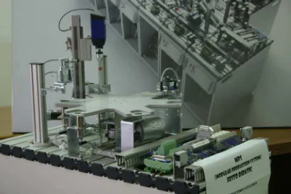
To machine workpieces andThe Processing station consists of the following
•
Rotary indexing table module•
Testing module•
Drilling module•
Clamping module•
Sorting gate module, electrical•
Profile plate•
Trolley•
Control console•
PLC boardProcessing station with trolley, control console and PLC board
Design and function
5.2 Function
In the processing station, workpieces are tested and processed on a rotary indexing table. The rotary indexing table is driven by a DC motor. The table is positioned by a relay circuit, with the position of the table being detected by an inductive sensor. On the rotary indexing table, the workpieces are tested and drilled in two parallel processes. A solenoid actuator with an inductive sensor checks that the workpieces are inserted in the correct position. During drilling, the workpiece is clamped by a solenoid actuator.
Finished workpieces are passed on via the electrical ejector. Note
The station uses exclusively electrical actuators. Starting prerequis ites
5.3
Sequence des cription
•
Workpiece is in the workpiece retainer material inputInitial pos ition
•
Rotary indexing table positioned•
Checking solenoid plunger raised•
Drilling machine in raised position•
Drilling machine motor is switched off•
Clamping device retractedEQUENCE
1. The rotary indexing table is rotated by 60°, if a workpiece is detected in the workpiece retainer 1 and the START pushbutton is pressed.
2. The solenoid plunger moves downwards and checks whether the workpiece is inserted with the opening facing upwards. The rotary indexing table is rotated by 60° if the result of the check is OK.
3. The clamping device clamps the workpiece. The motor of the drilling machine is switched on. The linear axis moves the drilling machine downwards.
4. When the drilling machine has reached its lower position, it is moved to its upper stop again by the linear axis.
5. The motor of the drilling machine is switched off and the clamping device is retracted. The rotary indexing table is rotated by 60°.
6. The electrical sorting gate passes on the workpiece to a subsequent station. This sequence describes the passage of ONE workpiece through the Processing
station. The workpiece is in the transfer position to a downstream station. The processing cycle can be started again, once a workpiece is inserted in the workpiece retainer 1.
Design and function
5.4
Rotary indexing table module
The drive of the Rotary indexing table module is operated by a DC gear motor. The 6 rotating plate positions are defined by the positioning screws on the rotary table and sensed by means of an inductive sensor.
5.5
Testing module
An inserted workpiece is checked for correct positioning. If the hole points upwards, then the armature of the testing solenoid reaches its end position.
An inductive proximity sensor is actuated via a nut at the upper end of the armature.
Design and function
5.6
Drilling module
The Drilling module is used to simulate the polishing of the hole of the workpiece. An electrical clamping device retains the workpiece. The feed and return actions of the drilling machine are effected by means of a linear axis with toothed belt drive. An electrical gear motor drives the linear axis and a relay circuit is used to activate the motor.
6. Commissioning
The stations of the Modular Production System are generally delivered
•
completely assembled•
operationally adjusted as single station•
commissioned•
testedNote
If stations are combined changes of the mechanical set-up and the position and setting of sensors may be necessary.
The commissioning is normally limited to a visual check to ensure correct tubing connections / wiring and supply of operating voltage.
All components, tubing and wiring is clearly marked so that all connections can be easily re-established.
The following is required to commission the MPS Station:
6.1
Workstation
•
The assembled and adjusted MPS station•
A control console•
A PLC board•
A power supply unit 24 V DC, 4.5 A6.2
M echanical set up
6.2.1 Assembling profile plate and control console
1
2 (4x)
4 (4x) 3
5 (2x) 6
1 Profile plate 2 T-head nut M6 x-32 (4x) 3 Trolley
4 Socket head screw M6x10 (4x) 5 Screw 3.5x9 (2x)
6 Control console
Commissioning
6.2.2 Assembling the station
6.3
Adjust sensors
6.3.1 Capacitive proximity sensor (Rotary indexing table, detection of workpiece)
The capacitive proximity sensor is used for detection of workpieces. The workpiece changes the capacity of a capacitor build in the sensor head. Workpieces are detected independent of colour and material.
Note
Capacitive proximity sensors are used in the positions material input, testing and drilling.
Prerequisite
– The Rotary indexing table module is assembled. – Proximity sensor is wired up.
– Power supply unit switched on.
Execution
1. Place a workpiece into the workpiece retainer.
2. Assemble the proximity sensor in the mounting bracket, avoid contact with the rotary indexing table. Position the proximity sensor centred below the drill hole of the workpiece retainer.
3. Adjust the distance proximity sensor – workpiece until the switching status display switches to on.
Note
Avoid activation of the proximity sensor by the rotating plate of the rotary indexing table.
4. Check position and setting of the proximity sensor (place/ pick up workpieces).
Documents
•
Data sheetsProximity sensor, capacitive (178575) in the directory English\ 3_Processing\ Data sheets on the CD-ROM supplied.
•
Assembly instructionsProcessing station in the directory English\ 3_Processing\ Assembly instructions on the CD-ROM supplied.
Commissioning
6.3.2 Inductive proximity s ens or (Rotary indexing table, Pos itioning)
The inductive proximity sensor is used for positioning of the rotary indexing table. Inductive proximity sensors detects metallic objects. The switching distance is a function of material and surface finish.
Prerequis ite
– The Rotary indexing table module is assembled. – Proximity sensor is wired up.
– Power supply unit switched on. Execution
1. Assemble the proximity sensor in the mounting bracket. Position the proximity sensor centred below the positioning screw of the rotary indexing table. The distance proximity sensor – positioning screw is ab out 2 mm.
2. Adjust the distance proximity sensor – positioni ng screw until the switching status display switches to on.
3. Check position and setting of the proximity sensor by rotation of the rotary indexing table.
Documents
•
Data sheetsProximity sensor, inductive (150395) in the directory English\ 3_Processing\ Data sheets on the CD-ROM supplied.
•
Assembly instructions6.3.3 Inductive proximity s ens or (Tes ting, orientation of workpiece)
The inductive proximity sensor is used for testing the orientation of the workpieces. Inductive proximity sensors detects metallic objects. The switching distance is a function of material and surface finish.
Prerequis ite
– The Rotary indexing table module and the Testing module are assembled. – Testing module and proximity sensor are wired up.
– Power supply unit switched on. Execution
1. Place a workpiece into the workpiece retainer. The hole points upwards. 2. Switch on the power supply of the coil of the Testing module.
3. Position the inductive proximity sensor in a distance of about 1 mm to the nut of the feeler of the Testing module.
4. Adjust the distance proximity sensor – nut until the switching status display switches to on.
5. Check position and setting of the proximity sensor by switching on and off the coil of the Testing module.
Documents
•
Data sheetsProximity sensor, inductive (150395) in the directory English\ 3_Processing\ Data sheets on the CD-ROM supplied.
•
Assembly instructionsProcessing station in the directory English\ 3_Processing\ Assembly instructions on the CD-ROM supplied.
Commissioning
6.3.4 M icro switch (Drilling, linear axis)
The micro switches are used for end stop sensing of the linear axis. The micro switches are actuated by the slide of the linear axis.
Prerequisite
– The Drilling module is assembled. – Drilling module is wired up – Micro switches are wired up – Power supply unit switched on.
Execution
1. Move the drilling machine to the upper end stop.
2. Shift the micro switch in the mounting bracket oblong holes until it is actuated. 3. Fix the clamping screws.
4. Move the drilling machine to the lower end stop.
5. Shift the micro switch in the mounting bracket oblong holes until it is actuated. 6. Fix the clamping screws.
7. Start a test run to check if the micro switches are positioned correctly (move drilling machine upwards/ downwards).
Documents
•
Data sheetsMicro switch S-3-E (007347) in the directory English\ 3_Processing\ Data sheets on the CD-ROM supplied.
•
Assembly instructionsProcessing station and Drilling module in the directory
6.4
VI SUAL CHECK
A visual check must be carried out before each commissioning! Prior to starting up the station, you will need to check:
•
The electrical connections•
The correct installation and condition of the compressed air connections•
The mechanical components for visual defects(tears, loose connections etc.)
Eliminate any damage detected prior to starting up the station!
Commissioning
1
2
6.5
Cable connections
Cable connections from PLC board to control console and station
1. PLC board – station
•
The stations are supplied with 24 V DC voltage (max. 5 A) via a power supply unit.6.6
Voltage s upply
•
The voltage supply of the complete station is effected via the PLC board.6.7.1 Siemens controller 6.7
Loading the PLC program
•
Controller: Siemens S7-313C, S7-313C-2DP, S7-314 or S7-315-2DP•
Programming software: Siemens STEP7 Version 5.1 or higher1. Connect PC and PLC using the RS232 programming cable with PC adapter 2. Switch on power supply unit
3. Switch on the compressed air supply
4. Release the EMERGENCY-STOP pushbutton (if available) 5. Overall reset PLC memory:
– Switch on the power supply unit and wait until the PLC has carried out its test routines.
– Turn the mode selector switch to MRES and keep the mode selector switch in this position until the STOP LED comes on for the second time and stays on. – Let go of the mode selector switch to STOP. Immediately you must turn the
mode selector switch back to MRES. The STOP LED starts to flash rapidly. – You can let go of the mode selector switch.
– When the STOP LED comes on permanently the memory reset is completed. – The PLC is ready for program download.
6. CPU switch in STOP position
7. Start the PLC programming software
Commissioning
8. Depending on your controller type, retrieve the file 31x.zip from the directory Sources\ PLC Programs\ Release C\ S7 of the CD-ROM supplied
File
Æ
Retrieve…Æ
Select an archive (CD ROM: Sources\ PLC Programs\ Release C\ S7) 31x.ZIPOpenÆ
Select destination directory OKÆ
Retrieving: The retrieved data were stored in the project directory. OKÆ
Retrieve: The following objects were retrieved. Do you want to open these now? Yes9. Select the project 3BE_AS or 3BE_KFA
10. Download the project to the controller
PLC
Æ
OWNLOADÆ
Follow the instructions on the screen11. Turn the mode selector switch of the CPU to RUN position
Commissioning
6.7.2 Festo/ Beck controller
•
Controller: Festo/ Beck FEC FC640, IPC CPU HC02, IPC CPU HC20•
Programming software: Festo FST Version 4.02or Klöpper und Wiege MULTIPROG wt Version 2.01
Festo FST Version 4.02
1. Connect PC and PLC using the TTL-RS232 programming cable 2. Switch on power supply unit
3. Switch on the compressed air supply
4. Release the EMERGENCY-STOP pushbutton (if available) 5. Start the PLC programming software
6. Restore the file 3BE_FEC.zip from the directory
Sources\ PLC Programs\ Release C\ FEC\ FST of the CD-ROM supplied
7. Compile the project
Project
Æ
Build Project8. Download the project to the controller
Online
Æ
Download ProjektÆ
Follow the instructions on the screenCommissioning
Klö pper und Wiege M ULTIPROG wt Version 2.01
1. Connect PC and PLC using the TTL-RS232 programming cable 2. Switch on power supply unit
3. Switch on the compressed air supply
4. Release the EMERGENCY-STOP pushbutton (if available)
Note
If you use the controllers Festo/ Beck IPC CPU HC02 oder IPC CPU HC20, you first have to download the I/ O configuration to the controller. Please proceed as follows: 5. Start the software „Transfer Tool“
6. Open the file MPSHCxx.mpr in the directory Sources\ PLC programs\ Release C\ IpcHCxx\ MWT\ IOConfig on the CD-ROM supplied
File
Æ
OpenÆ
Open file (CD ROM: Sources\ PLC programs\ Release C\ IpcHCxx\ MWT\ IOConfig, file type: * .mpr)M PSHCxx.mpr. Select Board1 (Node 1). Click right and select Connect over
Æ
COM. Select Connect Speed 38.400 kB/ s.The I/ O configuration is downloaded
8. Start the PLC programming software
9. Unzip the project 3BE_FEC.zwt from the directory
Sources\ PLC Programs\ Release C\ FEC\ MWT of the CD-ROM supplied
File
Æ
Open Projekt/ Unzip Project…Æ
Open/ unzip project (CD ROM: Sources\ PLC Programs\ Release C\ FEC\ MWT), File type: Zipped project files (* .zwt) 3BE_FEC.zwtUnzipÆ
All following requests YesCommissioning
10. Compile the project
Build
Æ
Rebuild Project6.8
Starting the sequence
1. Check the voltage supply.
2. Remove the workpieces at the transfer points of the modules or stations prior to manual reset.
3. Carry out the reset sequence. The reset sequence is prompted by an illuminated RESET pushbutton and executed after the pushbutton has been actuated. 4. Insert the workpiece in the workpiece retainer.
5. Start the sequence of the Processing station. The start is prompted using the illuminated START pushbutton and carried out after the pushbutton has been actuated.
Notes
•
The sequence can be interrupted at any time by pressing the EMERGENCY-STOP or the STOP pushbutton.•
With the key-operated switch AUTO/ MAN you can select either the continuous cycle (AUTO) or individual cycle (MAN).•
The following applies in the case of a combination of stations: The individual stations are reset against the material flow.•
The warning light WORKPIECE NOK is illuminated if the workpiece is incorrectly inserted. Remove the workpiece manually and acknowledge by pressing the START pushbutton.Commissioning
6.9
Combination of stations
6.9.1 Networking
In the standard version, the MPS stations are linked using optical sensors. This type of linking is known as StationLink, which uses through-beam sensor transmitters and receivers as sensors. The StationLink transmitter is mounted on the incoming material side and the StationLink receiver on the outgoing material side. By switching on or off the StationLink transmitter, the station signals the upstream station whether it is ready to receive a workpiece or busy.
The sensors for linking several stations must be arranged face to face in alignment. The linked stations must be securely interconnected by means of hammer head screws.
Note
7 AI NTENANCE
The Processing station is largely maintenance-free. The following should be cleaned at regular intervals using a soft fluff-free cloth or brush:
•
The lenses of the optical sensors, the fibre-optics and reflectors•
The active surface of the proximity sensor•
The entire stationAppendix
Note
All documents listed below are stored as pdf-files in the directory English\ 3_Processing on the CD-ROM supplied.
Processing station
Assembly instructions
Processing station
Equipment
Processing station, electrical
Circuit diagrams
S7-314 Symbols table
Program listings
S7-314 Overview
S7-314 Sequential function chart S7-314 Function block diagram
Processing station
Parts lists
Rotary indexing table module Testing module
Drilling module
Linear axis construction kit Drilling machine construction kit Limit switch construction kit Clamping module
86 © Festo Didactic GmbH & Co. KG 648813
Operating instructions Through-beam sensor, receiver 369 662
Through-beam sensor, transmitter 369 679
Data sheets Drilling machine 326 395
Gear motor drilling 526 867
Gear motor rotary indexing table 652 345
I/ O terminal 034 035
Linear axis with toothed belt drive DGEL-12 654 152
Micro switch S-3-E 007 347
Proximity sensor, capacitive 178 575
Proximity sensor, inductive SIEN-M8 150 395
Relay 268 327
Socket connector cable SIM-M8-3GD 159 420 Socket connector cable SIM-M8-4GD 158 960
Through-beam sensor, receiver 165 323
Through-beam sensor, transmitter 165 353
Up-to-date information and additional documents for the Technical documentation of the MPS stations please find at the address:
Updates
http:/ / www.festo.com/ didactic
M PS
®Stations
An overview of the M PS® stations Getting started with M PS®
Distributing station (V)
Focus on sensors
Testing station (P)
Purely electrical
Processing station (B)
M ultitalented
Handling station (H)
Fits anywhere
Buffer station (PU)
High-end
Robot station (R)
Add-on for the robot
Assembly station (M)
Hydraulics packs a punch
Punching station (HS)
Last but not least
PENDAHULUAN
1.1 Latar Belakang Masalah
Sejalan dengan perkembangan pesat perindustrian, maka mesin dan
peralatan industri yang digunakan juga terus berkembang pesat. Dalam era ini,
sebagian besar industri telah menggunakan teknologi otomasi industri. Dengan
mengkombinasikan antara mekanik, elektronik dan informatik pada otomasi
dalam proses industri. Teknologi otomasi ini, selain mengurangi waktu produksi
juga akan menggurangi nilai error yang terjadi dibandingkan jika dikerjakan
secara manual (dengan tenaga manusia).
Processing Station MPS (Modular Production System) yang terdiri dari
bagian rotary index table, testing, drilling, clamping dan sorting merupakan suatu
alat simulasi plant proses produksi. Jika proses produksi dirancang dan
disimulasikan terlebih dahulu sebelum diimplementasikan pada keadaan yang
sesungguhnya, akan meminimalisasi kerusakan pada plant. Banyak pengendali
yang dapat digunakan, salah satunya adalah PLC. PLC lebih tepat digunakan
dalam perindustrian mengingat daya tahannya yang tinggi dibandingkan dengan
mikrocontroller dalam kondisi industri dengan banyaknya keunggulan dan
multifungsi yang terdapat pada PLC seperti pemrograman dan pengeditan
program yang lebih mudah dan singkat dibandingkan dengan pengendali lainnya.
Untuk mengetahui lama siklus dan jumlah proses produksi yang telah
berlangsung, maka diperlukan suatu database. Database ini dibuat dengan
Bab I Pendahuluan
menggunakan software LabVIEW 7.1 yang telah menggunakan bahasa grafik
(graphical language, ”G”) untuk membuat program dalam bentuk flowchart, yang
disebut sebagai block diagram
sehingga dapat mempermudah proses
pemrograman, dan memiliki tampilan hasil yang menarik.
1.2 Identifikasi Masalah
1.
Bagaimana cara pengendalian Processing Station MPS dengan
menggunakan PLC Twido?
2.
Pembuatan sistem database Processing Station MPS dengan
menggunakan program LabVIEW 7.1
1.3 Tujuan
1. Merancang pengendalian simulasi plant dalam bentuk Processing
Station MPS dengan menggunakan PLC Twido.
2. Pembuatan data proses produksi dan disimpan dalam bentuk database
dengan menggunakan software LabVIEW 7.1.
1.4 Pembatasan Masalah
1.
MPS yang digunakan adalah Processing Station MPS yang terdiri dari
5 bagian proses produksi yaitu bagian rotary index table, testing,
memiliki lubang dengan ukuran diameter 2,5 cm dan tinggi 2 cm.
3.
PLC yang digunakan adalah PLC Twido
4.
Software yang digunakan dalam pemrograman PLC adalah Twidosoft.
5.
Software yang digunakan dalam pemrograman database adalah
LabVIEW 7.1.
1.5 Sistematika Penulisan
Laporan tugas akhir ini disusun dalam lima bab, dengan sistematika
penulisan sebagai berikut :
BAB I
PENDAHULUAN
Berisi latar belakang, identifikasi masalah, tujuan, pembatasan
masalah, dan sistematika penulisan.
BAB II
LANDASAN TEORI
Berisi pembahasan tentang istilah-istilah pengendalian, PLC dan
Prosessing station MPS.
BAB III
PEMROGRAMAN DAN PENGENDALIAN MPS
Berisi pembahasan tentang pemrograman pengendalian Prosessing
Station MPS dengan menggunakan PLC Twido.
BAB IV
PERHITUNGAN DAN ANALISA DATA
Berisi data-data hasil proses Prosessing Station MPS dalam bentuk
database.
BAB V
PENUTUP
Berisi kesimpulan dan saran.
Bab V Kesimpulan dan Saran
BAB V
KESIMPULAN DAN SARAN
5.1. Kesimpulan
Berdasarkan hasil pengujian dan pengamatan yang telah dilakukan, maka
dapat diambil beberapa kesimpulan, yaitu:
1.
Karena bahan material yang dipergunakan lebih dari 1, pemrograman PLC
untuk Prosessing Station MPS ini harus diprogram untuk melakukan proses
secara paralel.
2.
Total waktu proses keseluruhan untuk 1 bahan material metal adalah 21 detik
sedangkan untuk 1 bahan material non-metal adalah 14 detik. Kombinasi
bahan material dengan urutan acak untuk pada processing station MPS ini
total waktu prosesnya dapat ditentukan dengan pendekatan rumus
T
proses≈
t
mX
+
U
m1
+
U
m2
+
U
m3
+ … +
U
m(X-1)
yang memiliki persentase kebenaran sebesar 99%
material yang akan diproses.
5.1. Saran
Beberapa saran untuk pengembangan lebih lanjut yang lebih baik, yaitu:
1.
Perancangan dan pembuatan plant yang serupa tetapi dengan sistem dan
proses yang berbeda sehingga variable-variablenya kendalinya dapat lebih
fleksible untuk diubah dan dikendalikan.
2.
Penempatan proximity induktif dengan posisi di bawah piringan, akan
mendeteksi piringan itu sendiri selain bahan material metal yang akan
diproses. Untuk pengembangan lebih lanjut, piringan yang terbuat dari metal
dapat digantikan dengan bahan non-metal.
3.
Database tabel yang disimpan dalam program Excel, untuk pengembangan
lebih lanjut dapat dipergunakan program database yang lebih universal seperti
Access, SQL Server dan Oracle.
DAFTAR PUSTAKA
1.
Festo AG & Co, “Festo Didactic Processing Station Manual Hand
Boook”, 2003.
2.
PLC Training Center, “Diktat Pelatihan Advance Twido”, Bandung 2004.
3.