What Readers Are Saying About
Arduino: A Quick-Start Guide
The most comprehensive book on the Arduino platform I have read. Loaded with excellent examples and references,Arduino: A Quick-Start
Guide gets beginners up and running in no time and provides
experi-enced developers with a wealth of inspiration for their own projects.
Haroon Baig
Creator of the Twitwee Clock,http://www.haroonbaig.com
Excellently paced for those who have never experimented with elec-tronics or microcontrollers before and packed with valuable tidbits even for advanced Arduino tinkerers.
Georg Kaindl
Creator, Arduino DHCP, DNS, and Bonjour libs
The Arduino platform is a great way for anyone to get into embedded systems, and this book is the road map. From first baby steps to com-plex sensors and even game controllers, there is no better way to get going on the Arduino.
Tony Williamitis
Senior embedded systems engineer
I recommend this engaging and informative book to software develop-ers who want to learn the basics of electronics, as well as to anyone looking to interface their computers with the physical world.
René Bohne
Arduino
A Quick-Start Guide
Maik Schmidt
Many of the designations used by manufacturers and sellers to distinguish their prod-ucts are claimed as trademarks. Where those designations appear in this book, and The Pragmatic Programmers, LLC was aware of a trademark claim, the designations have been printed in initial capital letters or in all capitals. The Pragmatic Starter Kit, The Pragmatic Programmer, Pragmatic Programming, Pragmatic Bookshelf and the linkingg
device are trademarks of The Pragmatic Programmers, LLC.
Every precaution was taken in the preparation of this book. However, the publisher assumes no responsibility for errors or omissions, or for damages that may result from the use of information (including program listings) contained herein.
Our Pragmatic courses, workshops, and other products can help you and your team create better software and have more fun. For more information, as well as the latest Pragmatic titles, please visit us athttp://www.pragprog.com.
The team that produced this book includes:
Editor: Susannah Pfalzer Indexing: Potomac Indexing, LLC Copy edit: Kim Wimpsett
Layout: Samuel Langhorne Production: Janet Furlow Customer support: Ellie Callahan International: Juliet Benda
Copyright © 2011 Pragmatic Programmers, LLC.
All rights reserved.
No part of this publication may be reproduced, stored in a retrieval system, or transmit-ted, in any form, or by any means, electronic, mechanical, photocopying, recording, or otherwise, without the prior consent of the publisher.
Printed in the United States of America.
For Yvonne.
Contents
Acknowledgments 11
Preface 13
Who Should Read This Book . . . 14
What’s in This Book . . . 14
Arduino Uno and the Arduino Platform . . . 16
Code Examples and Conventions . . . 16
Online Resources . . . 17
The Parts You Need 18 Starter Packs . . . 18
Complete Parts List . . . 19
I
Getting Started with Arduino
22
1 Welcome to the Arduino 23 1.1 What You Need . . . 241.2 What Exactly Is an Arduino? . . . 24
1.3 Exploring the Arduino Board . . . 25
1.4 Installing the Arduino IDE . . . 31
1.5 Meeting the Arduino IDE . . . 33
1.6 Compiling and Uploading Programs . . . 38
1.7 Working with LEDs . . . 41
1.8 What If It Doesn’t Work? . . . 43
1.9 Exercises . . . 44
2 Inside the Arduino 46 2.1 What You Need . . . 46
2.2 Managing Projects and Sketches . . . 47
2.3 Changing Preferences. . . 48
2.4 Using Serial Ports . . . 49
2.5 What If It Doesn’t Work? . . . 60
CONTENTS 8
II
Eight Arduino Projects
62
3 Building Binary Dice 63
3.1 What You Need . . . 63
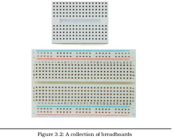
3.2 Working with Breadboards . . . 64
3.3 Using an LED on a Breadboard . . . 66
3.4 First Version of a Binary Die . . . 69
3.5 Working with Buttons. . . 74
3.6 Adding Our Own Button . . . 79
3.7 Building a Dice Game. . . 80
3.8 What If It Doesn’t Work? . . . 86
3.9 Exercises . . . 87
4 Building a Morse Code Generator Library 88 4.1 What You Need . . . 88
4.2 Learning the Basics of Morse Code . . . 88
4.3 Building a Morse Code Generator . . . 89
4.4 Fleshing Out the Generator’s Interface. . . 91
4.5 Outputting Morse Code Symbols . . . 92
4.6 Installing and Using the Telegraph Class . . . 94
4.7 Final Touches . . . 97
4.8 What If It Doesn’t Work? . . . 99
4.9 Exercises . . . 100
5 Sensing the World Around Us 102 5.1 What You Need . . . 103
5.2 Measuring Distances with an Ultrasonic Sensor . . 104
5.3 Increasing Precision Using Floating-Point Numbers 110 5.4 Increasing Precision Using a Temperature Sensor . 113 5.5 Transferring Data Back to Your Computer Using Pro-cessing . . . 119
5.6 Representing Sensor Data . . . 123
5.7 Building the Application’s Foundation . . . 125
5.8 Implementing Serial Communication in Processing 126 5.9 Visualizing Sensor Data . . . 128
5.10 What If It Doesn’t Work? . . . 131
CONTENTS 9
6 Building a Motion-Sensing Game Controller 132
6.1 What You Need . . . 133
7 Tinkering with the Wii Nunchuk 154 7.1 What You Need . . . 154
8 Networking with Arduino 170 8.1 What You Need . . . 171
8.2 Using Your PC to Transfer Sensor Data to the Inter-net . . . 172
8.8 Detecting Motion Using a Passive Infrared Sensor . 192 8.9 Bringing It All Together . . . 196
8.10 What If It Doesn’t Work? . . . 199
8.11 Exercises . . . 201
9 Creating Your Own Universal Remote Control 202 9.1 What You Need . . . 203
9.2 Understanding Infrared Remote Controls . . . 204
9.3 Grabbing Remote Control Codes . . . 205
9.4 Building Your Own Apple Remote . . . 209
CONTENTS 10
9.6 Building an Infrared Proxy . . . 214
9.7 What If It Doesn’t Work? . . . 221
9.8 Exercises . . . 222
10 Controlling Motors with Arduino 223 10.1 What You Need . . . 223
10.2 Introducing Motors . . . 224
10.3 First Steps with a Servo Motor . . . 225
10.4 Building a Blaminatr . . . 228
10.5 What If It Doesn’t Work? . . . 233
10.6 Exercises . . . 234
III
Appendixes
236
A Basics of Electronics 237 A.1 Current, Voltage, and Resistance . . . 237A.2 Learning How to Solder. . . 241
B Advanced Arduino Programming 247 B.1 The Arduino Programming Language. . . 247
B.2 Bit Operations . . . 249
C Advanced Serial Programming 251 C.1 Learning More About Serial Communication . . . . 251
C.2 Serial Communication Using Various Programming Languages . . . 253
D Bibliography 266
Acknowledgments
Writing books doesn’t get easier the more often I do it—I think there will never be a time when I can do it on my own. I will always depend on the help of others, and a lot of wonderful people contributed to this book.
I have to start by thanking my unbelievably talented editor, Susannah Davidson Pfalzer. Only because of her insightful advice, her patience, and her encouragement have I finished this book. I owe her so much!
Also, the Pragmatic Bookshelf team again has been amazingly profes-sional, and my publishers have been very sympathetic when I went through some hard times. I am so thankful for that!
This book would not have been possible without the stunning work of the whole Arduino team! Thank you so much for creating the Arduino!
A big “thank-you!” goes to all the people who contributed material to this book: Christian Rattat took all the book’s photos, Kaan Karaca created the Blaminatr’s display, and Tod E. Kurt kindly allowed me to use his excellent C code for accessing an Arduino via serial port.
I have created all circuit diagrams with Fritzing,1 and I’d like to thank
the Fritzing team for making such a great tool available for free!
For an author, there’s nothing more motivating than feedback. I’d like to thank my reviewers: René Bohne, Stefan Christoph, Georg Kaindl, Kaan Karaca, Christian Rattat, Stefan Rödder, Christoph Schwaeppe, Federico Tomassetti, and Tony Williamitis. This book is so much better because of your insightful comments and suggestions! I am also grate-ful to all readers who have sent in errata during the beta book period.
When I had written the first half of this book, my mother passed away in February 2010. It has been one of the hardest times in my life, and
ACKNOWLEDGMENTS 12
without the support of my family and my friends, I would have never finished this book. We miss you so much, Mom!
Preface
Welcome to the Arduino, and welcome to the exciting world of physical computing! Arduino2 is an open source project consisting of bothhard-ware and softhard-ware. It was originally created to give designers and artists a prototyping platform for interaction design courses. Today hobby-ists and experts all over the world use it to create physical computing projects, and you can too.
The Arduino lets us get hands-on again with computers in a way we haven’t been able to since the 1980s, when you could build your own computer. And Arduino makes it easier than ever to develop hand-crafted electronics projects ranging from prototypes to sophisticated gadgets. Gone are the days when you had to learn lots of theory about electronics and arcane programming languages before you could even get an LED blinking. You can create your first Arduino project in a few minutes without needing advanced electrical engineering course work.
In fact, you don’t need to know anything about electronics projects to read this book, and you’ll get your hands dirty right from the begin-ning. You’ll not only learn how to use some of the most important elec-tronic parts in the first pages, you’ll also learn how to write the software needed to bring your projects to life.
This book dispenses with theory and stays hands-on throughout. I’ll explain all the basics you need to build the book’s projects, and every chapter has a troubleshooting section to help when things go wrong. This book is a quick-start guide that gets you up to speed quickly and enables you to immediately create your own projects.
WHOSHOULDREADTHISBOOK 14
Who Should Read This Book
If you are interested in electronics—and especially in building your own toys, games, and gadgets—then this book is for you. Although the Arduino is a nice tool for designers and artists, only software developers are able to unleash its full power. So, if you’ve already developed some software—preferably with C/C++ or Java—then you’ll get a lot out of this book.
But there’s one more thing: you have to build, try, and modify the projects in this book. Have fun. Don’t worry about making mistakes. The troubleshooting sections—and the hands-on experience you’ll gain as you become more confident project by project—will make it all worth-while. Reading about electronics without doing the projects yourself isn’t even half the battle (you know the old saying: we remember 5 per-cent of what we hear, 10 perper-cent of what we write, and 95 perper-cent of what we personally suffer). And don’t be afraid: you really don’t need any previous electronics project experience!
If you’ve never written a piece of software before, start with a program-ming course or read a beginner’s book about programprogram-ming first (Learn
to Program [Pin06] is a nice starting point). Then, learn to program in
C with The C Programming Language [KR98] or in C++ with The C++
Programming Language[Str00].
What’s in This Book
This book consists of three parts (“Getting Started with Arduino,” “Eight Arduino Projects,” and the appendixes). In the first part, you’ll learn all the basics you need to build the projects in the second part, so read the chapters in order and do all the exercises. The chapters in the second part also build on each other, reusing techniques and code from earlier chapters.
Here’s a short walk-through:
WHAT’S INTHISBOOK 15
• Then you’ll learn how to work with analog and digital sensors. You’ll use a temperature sensor and an ultrasonic sensor to build a very accurate digital metering ruler. Then you’ll use a three-axis accelerometer to build your own motion-sensing game controller, together with a cool breakout game clone.
• In electronics, you don’t necessarily have to build gadgets yourself. You can also tinker with existing hardware, and you’ll see how easy it is to take full control of Nintendo’s Wii Nunchuk so you can use it in your own applications.
• Using a Nunchuk to control applications or devices is nice, but often it’s more convenient to have a wireless remote control. So, you’ll learn how to build your own universal remote control that you can even control using a web browser.
• Speaking of web browsers: connecting the Arduino to the Inter-net is easy, so you’ll build a burglar alarm that sends you an email whenever someone is moving in your living room during your absence.
• Finally, you’ll work with motors by creating a fun device for your next software project. It connects to your continuous integration system, and whenever the build fails, it moves an arrow to point to the name of the developer who is responsible.
• In the appendixes, you’ll learn about the basics of electricity and soldering. You’ll also find advanced information about program-ming a serial port and programprogram-ming the Arduino in general.
Every chapter starts with a detailed list of all parts and tools you need to build the chapter’s projects. Every chapter contains lots of photos and diagrams showing how everything fits together. You’ll get inspired with descriptions of real-world Arduino projects in sidebars throughout the book.
Things won’t always work out as expected, and debugging circuits can be a difficult and challenging task. So in every chapter you’ll find a “What If It Doesn’t Work?” section that explains the most common prob-lems and their solutions.
ARDUINOUNO AND THEARDUINOPLATFORM 16
into any problems, you’ll find a list of exercises to build your skills at the end of every chapter.
All the projects in this book have been tested on the Arduino Uno, the Arduino Duemilanove, and with the Arduino IDE versions 18 to 21. If possible, you should always use the latest version.
Arduino Uno and the Arduino Platform
After releasing several Arduino boards and Arduino IDE versions, the Arduino team decided to specify a version 1.0 of the platform. It will be the reference for all future developments, and they announced it on the first day of 2010.3 Since then, they have released the Arduino
Uno, and they have also improved the IDE and its supporting libraries step-by-step.
At the moment of this writing, it is still not completely clear what Arduino 1.0 will look like. The Arduino team tries to keep this release as backward compatible as possible. This book is up-to-date for the new Arduino Uno boards. All the projects will also work with older Arduino boards such as the Duemilanove or Diecimila. This book is current for version 21 of the Arduino platform. You can follow the progress of the Arduino platform online.4
Code Examples and Conventions
Although this is a book about open source hardware and electronics, you will find a lot of code examples. We need them to bring the hardware to life and make it do what we want it to do.
We use C/C++ for all programs that will eventually run on the Arduino. For applications running on our PC, we use Processing,5 but in
Sec-tionC.2,Serial Communication Using Various Programming Languages,
on page 253, you’ll also learn how to use several other programming languages to communicate with an Arduino.
Whenever you find a slippery road icon beside a paragraph, slow down and read carefully. They announce difficult or dangerous techniques.
3. http://arduino.cc/blog/2010/01/01/uno-punto-zero/
4. http://code.google.com/p/arduino/issues/list?q=milestone=1.0
ONLINERESOURCES 17
Online Resources
This book has its own web page athttp://pragprog.com/titles/msardwhere you can download the code for all examples (if you have the ebook ver-sion of this book, clicking the little gray box above each code example downloads that source file directly). You can also participate in a dis-cussion forum and meet other readers and me. If you find bugs, typos, or other annoyances, please let me and the world know about them on the book’s errata page.6
On the web page you will also find a link to a Flickr7 photo set. It
contains all the book’s photos in high resolution. There you can also see photos of reader projects, and we’d really like to see photos of your projects, too!
Let’s get started!
6. http://www.pragprog.com/titles/msard/errata
The Parts You Need
Here’s a list of the parts you need to work through all the projects in this book. In addition, each chapter lists the parts you’ll need for that chapter’s projects, so you can try projects chapter-by-chapter without buying all the components at once. Although there look to be a lot of components here, they’re all fairly inexpensive, and you can buy all the parts you need for all the projects in this book for about $200.Starter Packs
Many online shops sell Arduino components and electronic parts. Some of the best are Makershed8 and Adafruit.9 They have awesome starter
packs, and I strongly recommend buying one of these.
The best and cheapest solution is to buy the Arduino Projects Pack from Makershed (product code MSAPK). It contains nearly all the parts you need to build the book’s examples, as well as many more useful parts that you can use for your own side projects. If you buy the Arduino Projects Pack, you’ll need to buy these additional parts separately:
• Parallax PING))) sensor
• TMP36 temperature sensor from Analog Devices • ADXL335 accelerometer breakout board
• 6 pin 0.1" standard header • Nintendo Nunchuk controller • A Passive Infrared Sensor • An infrared LED
• An infrared receiver • An Ethernet shield
8. http://makershed.com
COMPLETEPAR TSLIST 19
Alternatively, Adafruit also sells an Arduino Starter Pack (product ID 170). It’s cheaper, but it doesn’t contain as many parts. For example, it doesn’t have a Protoshield or a tilt sensor.
All shops constantly improve their starter packs, so it’s a good idea to scan their online catalogs carefully.
Complete Parts List
If you prefer to buy parts piece by piece (or chapter by chapter) rather than a starter pack, here is a list of all the parts used in the book. Each chapter also has a parts list and photo with all parts needed for that chapter. Suggested websites where you can buy the parts are listed here for your convenience, but many of these parts are available elsewhere also, so feel free to shop around.
Good shops for buying individual components parts are RadioShack,10
Digi-Key,11 sparkfun,12and Mouser.13
• An Arduino board such as the Uno, Duemilanove, or Diecimila available from Adafruit (product ID 50) or Makershed (product code MKSP4).
• A standard A-B USB cable for USB 1.1 or 2.0. You might already have a few. If not, you can order it at RadioShack (catalog number 55011289).
• A half-size breadboard from Makershed (product code MKKN2) or from Adafruit (product ID 64).
• Three LEDs (four additional ones are needed for an optional exer-cise). Buying LEDs one at a time isn’t too useful; a better idea is to buy a pack of 20 at RadioShack (catalog number 276-1622).
• One 100Ω resistor, two 10kΩ resistors, and three 1kΩ resistors.
It’s also not too useful to buy single resistors; buy a value pack such as catalog number 271-308 from RadioShack.
• Two pushbuttons. Don’t buy a single button switch; buy at least four instead, available at RadioShack (catalog number 275-002).
10. http://radioshack.com
11. http://digikey.com
12. http://sparkfun.com
COMPLETEPAR TSLIST 20
• Some wires, preferably breadboard jumper wires. You can buy them at Makershed (product code MKSEEED3) or Adafruit (prod-uct ID 153).
• A Parallax PING))) sensor (product code MKPX5) from Makershed.
• A Passive Infrared Sensor (product code MKPX6) from Makershed.
• A TMP36 temperature sensor from Analog Devices.14 You can get
it from Adafruit (product ID165).
• An ADXL335 accelerometer breakout board. You can buy it at Adafruit (product ID 163).
• A 6 pin 0.1" standard header (included, if you order the ADXL335 from Adafruit). Alternatively, you can order from sparkfun (search
for breakaway headers). Usually, you can only buy stripes that
have more pins. In this case, you have to cut it accordingly.
• A Nintendo Nunchuk controller. You can buy it at nearly every toy store or athttp://www.amazon.com/, for example.
• An Arduino Ethernet shield (product code MKSP7) from Maker-shed.
• An infrared sensor such as the PNA4602. You can buy it a Adafruit (product ID 157) or Digi-Key (search forPNA4602).
• An infrared LED. You can get it from RadioShack (catalog number 276-143) or from sparkfun (search forinfrared LED).
• A 5V servo motor such as the Hitec HS-322HD or the Vigor Hex-tronic. You can get one from Adafruit (product id 155) or sparkfun. Search for standard servos with an operating voltage of 4.8V–6V.
For some of the exercises, you’ll need some optional parts:
• An Arduino Proto Shield from Adafruit (product ID 51) or Maker-shed (product code MKAD6). You’ll also need a tiny breadboard (product code MKKN1 at Makershed). I highly recommend this shield!
• A piezo speaker or buzzer. Search forpiezo buzzer at RadioShack or get it from Adafruit (product ID 160).
COMPLETEPAR TSLIST 21
• A tilt sensor. Get it from Adafruit (product ID 173), or buy it at Mouser (part number 107-2006-EV).
For the soldering tutorial, you need the following things:
• A 25W–30W soldering iron with a tip (preferably 1/16") and a sol-dering stand.
• Standard 60/40 solder (rosin-core) spool for electronics work. It should have a 0.031" diameter.
• A sponge.
Part I
Chapter 1
Welcome to the Arduino
The Arduino was originally built for designers and artists—people with little technical expertise. Even without programming experience, the Arduino enabled them to create sophisticated design prototypes and some amazing interactive artworks. So, it should come as no surprise that the first steps with the Arduino are very easy, even more so for people with a strong technical background.But it’s still important to get the basics right. You’ll get the most out of working with the Arduino if you’re familiar with the Arduino board itself, with its development environment, and with techniques such as serial communication.
One thing to understand before getting started isphysical computing. If you have worked with computers before, you might wonder what this means. After all, computers are physical objects, and they accept input from physical keyboards and mice. They output sound and video to physical speakers and displays. So, isn’t all computing physical com-puting in the end?
WHATYOUNEED 24
1.1
What You Need
• An Arduino board such as the Uno, Duemilanove, or Diecimila.
• A USB cable to connect the Arduino to your computer.
• An LED.
• The Arduino IDE (see Section 1.4, Installing the Arduino IDE, on page 31). You will need it in every chapter, so after this chapter, I’ll no longer mention it explicitly.
1.2
What Exactly Is an Arduino?
Beginners often get confused when they discover the Arduino project. When looking for the Arduino, they hear and read strange names such as Uno, Duemilanove, Diecimila, LilyPad, or Seeduino. The problem is that there is no such thing as “the Arduino.”
A couple of years ago the Arduino team designed a microcontroller board and released it under an open source license. You could buy fully assembled boards in a few electronics shops, but people interested in electronics could also download its schematic1 and build it themselves.
Over the years the Arduino team improved the board’s design and released several new versions. They usually had Italian names such as Uno, Duemilanove, or Diecimila, and you can find a list of all boards that were ever created by the Arduino team online.2
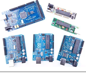
Figure1.1, on the following page shows a small selection of Arduinos. They may differ in their appearance, but they have a lot in common, and you can program them all with the same tools and libraries.
The Arduino team did not only constantly improve the hardware design. They also invented new designs for special purposes. For example, they created the Arduino LilyPad3 to embed a microcontroller board into
textiles. You can use it to build interactive T-shirts, for example.
In addition to the official boards, you can find countless Arduino clones on the Web. Everybody is allowed to use and change the original board design, and many people created their very own version of an Arduino-compatible board. Among many others, you can find the Freeduino,
1. http://arduino.cc/en/uploads/Main/arduino-uno-schematic.pdf
2. http://arduino.cc/en/Main/Boards
EXPLORING THEARDUINOBOARD 25
Figure 1.1: You can choose fom many different Arduinos.
Seeduino, Boarduino, and the amazing Paperduino,4 an Arduino clone
without a printed circuit board. All its parts are attached to an ordinary piece of paper.
Arduino is a registered trademark—only the official boards are named “Arduino.”—so clones usually have names ending with “duino.” You can use every clone that is fully compatible with the original Arduino to build all the book’s projects.
1.3
Exploring the Arduino Board
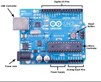
In Figure1.2, on the next page, you can see a photo of an Arduino Uno board and its most important parts. I’ll explain them one by one. Let’s start with the USB connector. To connect an Arduino to your computer,
EXPLORING THEARDUINOBOARD 26
!"#"$%&'()*'+",-+./01'2%34 567'8.,,03$.1
90-0$ 7:$$.,
;"31.< 8.,$1.&&01
+./01'6:==&>
?,%&.#'(,=:$'+",-Figure 1.2: The Arduino’s most important components
you just need an USB cable. Then you can use the USB connection for various purposes:
• Upload new software to the board (you’ll see how to do this in Section1.6,Compiling and Uploading Programs, on page38).
• Communicate with the Arduino board and your computer (you’ll learn that in Section2.4,Using Serial Ports, on page 49).
• Supply the Arduino board with power.
EXPLORING THEARDUINOBOARD 27
Figure 1.3: You can power an Arduino with an AC adapter.
In these situations, the best solution usually is an AC adapter (see Figure 1.3) supplying 9 volts (the recommended range is 7V to 12V).5
You need an adapter with a 2.1 mm barrel tip and a positive center (you don’t need to understand what that means right now; just ask for it in your local electronics store). Plug it into the Arduino’s power jack, and it will start immediately, even if it isn’t connected to a computer. By the way, even if you connect the Arduino to an USB port, it will use the external power supply if available.
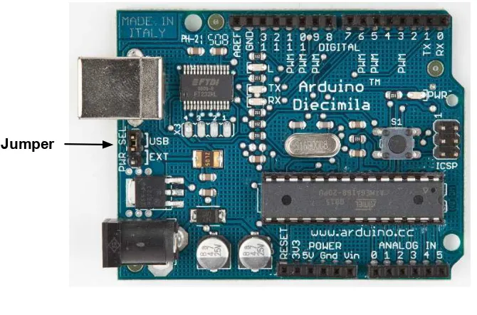
Please note that older versions of the Arduino board (Arduino-NG and Diecimila) don’t switch automatically between an external power supply and a USB supply. They come with a power selection jumper labeled
PWR_SEL, and you manually have to set it to EXT or USB, respectively
(see Figure1.4, on the next page).
Now you know two ways to supply the Arduino with power. But the Arduino isn’t greedy and happily shares its power with other devices. At the bottom of Figure1.2, on the preceding page, you can see several sockets (sometimes I’ll also call thempins, because internally they are connected to pins in the microcontroller) related to power supply:
• Using the pins labeled3V3and5V, you can power external devices connected to the Arduino with 3.3 volts or 5 volts.
EXPLORING THEARDUINOBOARD 28
!"#$%&
Figure 1.4: Older Arduinos have a power source selection jumper.
• Two ground pins labeledGndallow your external devices to share a common ground with the Arduino.
• Some projects need to be portable, so they’ll use a portable power supply such as batteries. You connect an external power source such as a battery pack to the VinandGnd sockets.
If you connect an AC adapter to the Arduino’s power jack, you can supply the adapter’s voltage through this pin.
On the lower right of the board, you see six analog input pins named A0–A5. You can use them to connect analog sensors to the Arduino. They take sensor data and convert it into a number between 0 and 1023. In Chapter 5, Sensing the World Around Us, on page 102, we’ll use them to connect a temperature sensor to the Arduino.
EXPLORING THEARDUINOBOARD 29
Analog and Digital Signals
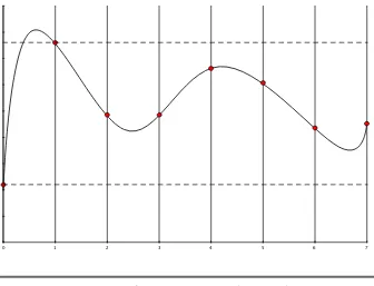
Nearly all physical processes are analog. Whenever you observe a natural phenomenon such as electricity or sound, you’re actually receiving an analog signal. One of the most important properties of these analog signals is that they are continuous. For every given point in time, you can measure the strength of the signal, and in principle you could register even the tiniest variation of the signal.
But although we live in an analog world, we are also living in the digital age. When the first computers were built a few decades ago, people quickly realized that it’s much easier to work with real-world information when it’s represented as num-bers and not as an analog signal such as voltage or volume. For example, it’s much easier to manipulate sounds using a com-puter when the sound waves are stored as a sequence of num-bers. Every number in this sequence could represent the signal’s loudness at a certain point in time.
So instead of storing the complete analog signal (as is done on records), we measure the signal only at certain points in time (see Figure 1.5, on the following page). We call this pro-cesssampling, and the values we store are calledsamples. The frequency we use to determine new samples is calledsampling rate. For an audio CD, the sampling rate is 44.1 kHz: we gather 44,100 samples per second.
We also have to limit the samples to a certain range. On an audio CD, every sample uses 16 bits. In Figure1.5, on the next page, the range is denoted by two dashed lines, and we had to cut off a peak at the beginning of the signal.
EXPLORING THEARDUINOBOARD 30
!
" # $ % & ' (
Figure 1.5: Digitizing an analog signal
output pins. In this mode, they convert values from 0 to 255 into an analog voltage.
All these pins are connected to amicrocontroller. A microcontroller com-bines a CPU with some peripheral functions such as IO channels. Many different types of microcontrollers are available, but the Arduino usu-ally comes with an ATmega328 or an ATmega168. Both are 8-bit micro-controllers produced by a company named Atmel.
INSTALLING THEARDUINO IDE 31
In this section, we had a closer look at the Arduino Uno, the newest Arduino board. But several other types are available, and although they’re the same in principle, they differ in some details. The Arduino Mega25606 has many more IO pins than all other Arduinos and uses
the powerful ATmega2560 microcontroller, while the Arduino Nano7
was designed to be used on a breadboard, so it doesn’t have any sock-ets. From my experience, beginners should start with one of the “stan-dard” boards, that is, with an Uno or a Duemilanove.
1.4
Installing the Arduino IDE
To make it as easy as possible to get started with the Arduino, the Arduino developers have created a simple but useful integrated devel-opment environment (IDE). It runs on many different operating sys-tems. Before you can create your first projects, you have to install it.
Installing the Arduino IDE on Windows
The Arduino IDE runs on all the latest versions of Microsoft Windows, such as Windows XP, Windows Vista, and Windows 7. Installing the software is easy, because it comes as a self-contained ZIP archive,8 so
you don’t even need an installer. Download the archive, and extract it to a location of your choice.
Before you first start the IDE, you must install drivers for the Arduino’s USB port. This process depends on the Arduino board you’re using and on your flavor of Windows, but you always have to plug the Arduino into a USB port first to start the driver installation process.
On Windows Vista, driver installation usually happens automatically. Lean back and watch the hardware wizard’s messages pass by until it says that you can use the newly installed USB hardware.
Windows XP and Windows 7 may not find the drivers on Microsoft’s update sites automatically. Sooner or later the hardware wizard asks you for the path to the right drivers after you have told it to skip auto-matic driver installation from the Internet. Depending on your Arduino board, you have to point it to the right location in the Arduino installa-tion directory. For the Arduino Uno and the Arduino Mega 2560, choose
6. http://arduino.cc/en/Main/ArduinoBoardMega2560
7. http://arduino.cc/en/Main/ArduinoBoardNano
INSTALLING THEARDUINO IDE 32
Arduino UNO.inf (respectively, Arduino MEGA 2560.inf) in the drivers
direc-tory. For older boards such as the Duemilanove, Diecimila, or Nano, choose thedrivers/FTDI USB Driversdirectory
After the drivers have been installed, you can start the Arduino exe-cutable from the archive’s main directory by double-clicking it. Follow the instructions on the screen to install the IDE.
Please note that the USB drivers don’t change as often as the Arduino IDE. Whenever you install a new version of the IDE, check whether you have to install new drivers, too. Usually, it isn’t necessary.
Installing the Arduino IDE on Mac OS X
The Arduino IDE is available as a disk image for the most recent Mac OS X.9 Download it, double-click it, and then drag the Arduino icon to
yourApplicationsfolder.
If you’re using an Arduino Uno or an Arduino Mega 2560, you are done and can start the IDE. Before you can use the IDE with an older Arduino such as the Duemilanove, Diecimila, or Nano, you have to install drivers for the Arduino’s serial port. A universal binary is in the disk image—double-click theFTDIUSBSerialDriver_10_4_10_5_10_6.pkgfile for your platform, and follow the installation instructions on the screen.
When installing a new version of the Arduino IDE, you usually don’t have to install the FTDI drivers again (only when a more recent version of the drivers is available).
Installing the Arduino IDE on Linux
Installation procedures on Linux distributions are still not very homo-geneous. The Arduino IDE works fine on nearly all modern Linux ver-sions, but the installation process heavily differs from distribution to distribution. Also, you often have to install additional software (the Java virtual machine, for example) that comes preinstalled with other oper-ating systems.
It’s best to check the official documentation10and look up the
instruc-tions for your preferred system.
Now that we have the drivers and the IDE installed, let’s see what it has to offer.
9. http://arduino.cc/en/Main/Software
MEETING THEARDUINO IDE 33
Figure 1.6: The Arduino IDE is well arranged.
1.5
Meeting the Arduino IDE
MEETING THEARDUINO IDE 34
!"#$%&
'()*
+",
-*".
'/0"
1*2)/3
'"#$/245).$()#
Figure 1.7: The IDE’s toolbar gives you quick access to important func-tions.
It has no advanced features such as a debugger or code completion. You can change only a few preferences, and as a Java application it does not fully integrate into the Mac desktop. It’s still usable, though, and even has decent support for project management.
In Figure 1.7, you can see the IDE’s toolbar that gives you instant access to the functions you’ll need most:
• With the Verify button, you can compile the program that’s cur-rently in the editor. So, in some respects, “Verify” is a bit of a misnomer, because clicking the button does not only verify the program syntactically. It also turns it into a representation suit-able for the Arduino board.
• The New button creates a new program by emptying the content of the current editor window. Before that happens, the IDE gives you the opportunity to store all unsaved changes.
• With Open, you can open an existing program from the file system.
• Save saves the current program.
MEETING THEARDUINO IDE 35
!"#$%
&'(')*+,-.
&$%/(0 1"22)3/4('/"3
Figure 1.8: The Arduino board comes with several LEDs.
the IDE’s Tools > Serial Port menu (you’ll learn more about this in Section1.6,Compiling and Uploading Programs, on page38).
• The Arduino can communicate with a computer via a serial con-nection. Clicking the Serial Monitor button opens a serial monitor window that allows you to watch the data sent by an Arduino and also to send data back.
• The Stop button stops the serial monitor.
Although using the IDE is easy, you might run into problems or want to look up something special. In such cases, take a look at the Help menu. It points to many useful resources at the Arduino’s website that provide quick solutions not only to all typical problems but also to reference material and tutorials.
To get familiar with the IDE’s most important features, we’ll create a simple program that makes an light-emitting diode (LED) blink. An LED is a cheap and efficient light source, and the Arduino already comes with several LEDs. One LED shows whether the Arduino is cur-rently powered, and two other LEDs blink when data is transmitted or received via a serial connection (see them in Figure1.8).
In our first little project, we’ll make the Arduino’s status LED blink. The status LED is connected to digital IO pin 13. Digital pins act as a kind of switch and can be in one of two states: HIGH or LOW. If set to HIGH, the output pin is set to 5 volts, causing a current to flow through the LED, so it lights up. If it’s set back to LOW, the current flow stops, and the LED turns off. You do not need to know exactly how electricity works at the moment, but if you’re curious, take a look at SectionA.1,
MEETING THEARDUINO IDE 36
Open the IDE, and enter the following code in the editor:
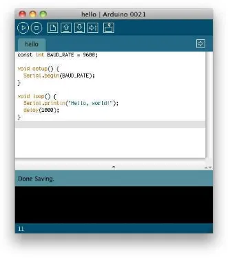
Download welcome/HelloWorld/HelloWorld.pde
Line 1 const unsigned int LED_PIN = 13;
- const unsigned int PAUSE = 500;
-Let’s see how this works and dissect the program’s source code piece by piece. In the first two lines we define two int constants using the const keyword.LED_PINrefers to the number of the digital IO pin we’re using,
andPAUSEdefines the length of the blink period in milliseconds.
Every Arduino program needs a function namedsetup( ), and ours starts in line 4. A function definition always adheres to the following scheme:
<return value type> <function name> ’(’ <list of parameters> ’)’
In our case the function’s name is setup( ), and its return value type is void: it returns nothing.setup( ) doesn’t expect any arguments, so we left the parameter list empty. Before we continue with the dissection of our program, you should learn a bit more about the Arduino’s data types.
Arduino Data Types
Every piece of data you store in an Arduino program needs a type. Depending on your needs, you can choose from the following:
• booleanvalues take up one byte of memory and can betrueorfalse.
• char variables take up one byte of memory and store numbers from -128 to 127. These numbers usually represent characters encoded in ASCII; that is, in the following example,c1andc2have the same value:
char c1 = 'A';
char c2 = 65;
Note that you have to use single quotes forcharliterals.
MEETING THEARDUINO IDE 37
• Anint variable needs two bytes of memory; you can use it to store numbers from -32,768 to 32,767. Its unsigned pendant unsigned int also consumes two bytes of memory but stores numbers from 0 to 65,535.
• For bigger numbers, use long. It consumes four bytes of mem-ory and stores values from -2,147,483,648 to 2,147,483,647. The unsigned variant unsigned long also needs four bytes but ranges from 0 to 4,294,967,295.
• float and double are the same at the moment, and you can use
these types for storing floating-point numbers. Both use four bytes of memory and are able to store values from -3.4028235E+38 to 3.4028235E+38.
• You need void only for function declarations. It denotes that a function doesn’t return a value.
• Arrays store collections of values having the same type:
int values[2]; // A two-element array
int values[0] = 42; // Set the first element
int values[1] = -42; // Set the second element
int more_values[] = { 42, -42 };
int first = more_values[0]; // first == 42
In the preceding example, the arrays values andmore_values con-tain the same elements. We have used only two different ways of initializing an array. Note that the array index starts at 0, and keep in mind that uninitialized array elements contain random values.
• A string is an array ofcharvalues. The Arduino environment sup-ports the creation of strings with some syntactic sugar—all these declarations create strings with the same contents.
char string1[8] = { 'A', 'r', 'd', 'u', 'i', 'n', 'o', '\0' };
char string2[] = "Arduino";
char string3[8] = "Arduino";
char string4[] = { 65, 114, 100, 117, 105, 110, 111, 0 };
Strings should always be terminated by a zero byte. When you use double quotes to create a string, the zero byte will be added automatically. That’s why you have to add one byte to the size of the corresponding array.
COMPILING ANDUPLOADINGPROGRAMS 38
Arduino callssetup( ) once when it boots, and we use it for initializing the Arduino board and all the hardware we have connected to it. We use
the pinMode( ) method to turn pin 13 into an output pin. This makes
sure the pin is able to provide enough current to light up an LED. The default state of a pin isINPUT, and bothINPUTandOUTPUTare predefined constants.11
Another mandatory function namedloop( ) begins in line 8. It contains the main logic of a program, and the Arduino calls it in an infinite loop. Our program’s main logic has to turn on the LED connected to pin 13 first. To do this, we usedigitalWrite( ) and pass it the number of our pin and the constant HIGH. This means the pin will output 5 volts until further notice, and the LED connected to the pin lights up.
The program then calls delay( ) and waits for 500 milliseconds doing nothing. During this pause, pin 13 remains inHIGHstate, and the LED continues to burn. The LED is eventually turned off when we set the pin’s state back to LOWusing digitalWrite( ) again. We wait another 500 milliseconds, and then the loop( ) function ends. The Arduino starts it again, and the LED blinks.
In the next section, you’ll learn how to bring the program to life and transfer it to the Arduino.
1.6
Compiling and Uploading Programs
Before you compile and upload a program to the Arduino, you have to configure two things in the IDE: the type of Arduino you’re using and the serial port your Arduino is connected to.
Identifying the Arduino type is easy, because it is printed on the board. Popular types are Uno, Duemilanove, Diecimila, Nano, Mega, Mini, NG, BT, LilyPad, Pro, or Pro Mini. In some cases, you also have to check what microcontroller your Arduino uses—most have an ATmega168 or an ATmega328. You can find the microcontroller type printed on the microcontroller itself. When you have identified the exact type of your Arduino, choose it from the Tools > Board menu.
Now you have to choose the serial port your Arduino is connected to from the Tools > Serial Port menu. On Mac OS X, the name of the serial port starts with/dev/cu.usbserialor/dev/cu.usbmodem(on my
COMPILING ANDUPLOADINGPROGRAMS 39
MacBook Pro, it’s/dev/cu.usbmodemfa141). On Linux systems, it should
be /dev/ttyUSB0, /dev/ttyUSB1, or something similar depending on the
number of USB ports your computer has.
On Windows systems, it’s a bit more complicated to find out the right serial port, but it’s still not difficult. Go to the Device Manager, and look for USB Serial Port below the Ports (COM & LPT) menu entry (see Figure 1.9, on the following page). Usually the port is named COM1, COM2, or something similar.
After you have chosen the right serial port, click the Verify button, and you should see the following output in the IDE’s message area (the Arduino IDE calls programssketches):
Binary sketch size: 1010 bytes (of a 32256 byte maximum)
This means the IDE has successfully compiled the source code into 1,010 bytes of machine code that we can upload to the Arduino. If you see an error message instead, check whether you have typed in the program correctly (when in doubt, download the code from the book’s website).12Depending on the Arduino board you’re using, the byte
max-imum may differ. On an Arduino Duemilanove, it’s usually 14336, for example.
Now click the Upload button, and after a few seconds, you should see the following output in the message area:
Binary sketch size: 1010 bytes (of a 32256 byte maximum)
This is exactly the same message we got after compiling the program, and it tells us that the 1,010 bytes of machine code were transferred successfully to the Arduino. In case of any errors, check whether you have selected the correct Arduino type and the correct serial port in the Tools menu.
During the upload process, the TX and RX LEDs will flicker for a few seconds. This is normal, and it happens whenever the Arduino and your computer communicate via the serial port. When the Arduino sends information, it turns on the TX LED. When it gets some bits, it turns on the RX LED. Because the communication is pretty fast, the LEDs start to flicker, and you cannot identify the transmission of a single byte (if you can, you are probably an alien).
COMPILING ANDUPLOADINGPROGRAMS 40
WORKING WITHLEDS 41
Figure 1.10: What’s happening on pin 13 while the LED blinks.
As soon as the code has been transmitted completely, the Arduino exe-cutes it. In our case, this means the status LED starts to blink. It turns on for half a second, then it turns off for half a second, and so on.
In Figure 1.10, you can see a diagram showing the activity on the pin while the program is running. The pin starts inLOWstate and does not output any current. We set it toHIGHin the software usingdigitalWrite( ) and let it output 5 volts for 500 milliseconds. Finally, we set it back to
LOWfor 500 milliseconds and repeat the whole process.
Admittedly, the status LED does not look very spectacular. So, in the next section, we’ll attach a “real” LED to the Arduino.
1.7
Working with LEDs
The LEDs that come with the Arduino are nice for testing purposes, but you should not use them in your own electronics projects. They all have a specific meaning, and it’s bad style to use them in a different context. Also, they are very small and not very bright, so it’s a good idea to get some additional LEDs and learn how to connect them to the Arduino. It’s really easy.
We will not use the same type of LEDs that are mounted on the Arduino board. They are surface-mounted devices (SMD) that are difficult to handle. You will rarely work with SMD parts, because for most of them you need special equipment and a lot of experience. They save costs as soon as you start mass production of an electronic device, but pure hobbyists won’t need them often.
WORKING WITHLEDS 42
Figure 1.11: A collection of through-hole LEDs
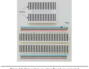
why they usually have one or more long wires. First you put the wires through holes in a printed circuit board. Then you usually bend, sol-der, and cut them to attach the part to the board. Where available, you can also plug them into sockets as we have them on the Arduino or on breadboards (you’ll learn more about breadboards in Section 3.2,
Working with Breadboards, on page64).
In Figure 1.12, on the following page, you can see how to attach an LED to an Arduino. Put the short connector of the LED to the ground pin (GND) and the longer one to pin 13. You can do that while the blink sketch is still running. Both the status LED and the external LED will start to blink.
Make absolutely sure that you’re using pin 13! If you connect the LED to any other pin, it will probably be destroyed. The reason is that pin 13 has an internal resistor that the other pins don’t have (you’ll learn more about this in Chapter3,Building Binary Dice, on page63).
That’s it! You’ve just added your first external electronics part to your Arduino, and you have created your first physical computing project. You’ve written some code, and it makes the world a bit brighter. Your very own digital version of “fiat lux.”13
You will need the theory and skills you have learned in this chapter for nearly every Arduino project. In the next chapter, you’ll see how to gain more control over LEDs, and you’ll learn how to benefit from more advanced features of the Arduino IDE.
WHATIFITDOESN’TWORK? 43
Figure 1.12: Connect an LED to the Arduino.
1.8
What If It Doesn’t Work?
EXERCISES 44
Choosing the wrong serial port or Arduino type also is a common mis-take. If you get an error message such as “Serial port already in use” when uploading a sketch, check whether you have chosen the right serial port from the Tools > Serial Port menu. If you get messages such as “Problem uploading to board” or “programmer is not respond-ing,” check whether you have chosen the right Arduino board from the Tools > Board menu.
Your Arduino programs, like all programs, will contain bugs. Typos and syntax errors will be detected by the compiler. In Figure1.13, on the fol-lowing page, you can see a typical error message. Instead ofpinMode( ), we called pinMod( ), and because the compiler did not find a function having that name, it stopped with an error message. The Arduino IDE highlights the line, showing the error with a yellow background, and prints a helpful error message.
Other bugs might be more subtle and sometimes you have to care-fully study your code and use some plain old debugging techniques (in
Debug It! Find, Repair, and Prevent Bugs in Your Code [But09] you can
find plenty of useful advice on this topic).
It might happen—although it’s rare—that you actually have a damaged LED. If none of the tricks mentioned helps, try another LED.
1.9
Exercises
• Try different blink patterns using more pauses and vary the pause length (they don’t necessarily have to be all the same). Also, exper-iment with very short pauses that make the LED blink at a high frequency. Can you explain the effect you’re observing?
• Let the LED output your name in Morse code.14
EXERCISES 45
Chapter 2
Inside the Arduino
For simple applications, all you have learned about the Arduino IDE in the preceding chapter is sufficient. But soon your projects will get more ambitious, and then it will come in handy to split them into separate files that you can manage as a whole. So in this chapter, you’ll learn how to stay in control over bigger projects with the Arduino IDE.Usually, bigger projects need not only more software but also more hardware—you will rarely use the Arduino board in isolation. For exam-ple, you will use many more sensors than you might imagine, and you’ll have to transmit the data they measure back to your computer. To exchange data with the Arduino, you’ll use its serial port. This chapter explains everything you need to know about serial communication. To make things more tangible, you’ll learn how to turn your computer into a very expensive light switch that lets you control an LED using the keyboard.
2.1
What You Need
To try this chapter’s examples, you need only a few things:
• An Arduino board such as the Uno, Duemilanove, or Diecimila
• A USB cable to connect the Arduino to your computer
• An LED (optional)
• A software serial terminal such as Putty (for Windows users) or
MANAGINGPROJECTS ANDSKETCHES 47
2.2
Managing Projects and Sketches
Modern software developers can choose from a variety of development tools that automate repetitive and boring tasks. That’s also true for embedded systems like the Arduino. You can use integrated develop-ment environdevelop-ments (IDEs) to manage your programs, too. The most popular one has been created by the Arduino team.
The Arduino IDE manages all files belonging to your project. It also pro-vides convenient access to all the tools you need to create the binaries that will run on your Arduino board. Conveniently, it does so unob-trusively. For example, you might have noticed that the Arduino IDE stores all code you enter automatically. This is to prevent beginners from losing data or code accidentally (not to mention that even the pros lose data from time to time, too).
Organizing all the files belonging to a project automatically is one of the most important features of an IDE. Under the hood, the Arduino IDE creates a directory for every new project, and it stores all the files belonging to the project in this directory. To add new files to a project, click the tabs button on the right to open the tabs pop-up menu, and then choose New Tab (see Figure2.1). To add an existing file, use the Sketch > Add File menu item.
As you might have guessed already from the names of the menu items, the Arduino IDE calls projects sketches. If you do not choose a name, it gives them a name starting with sketch_. You can change the name whenever you like using the Save As command. If you do not save a sketch explicitly, the IDE stores it in a predefined folder you can look
CHANGINGPREFERENCES 48
up in the preferences menu. You can change this behavior so that the IDE asks you for a name when you create a new sketch. Whenever you get lost, you can check what folder the current sketch is in using the Sketch > Show Sketch Folder menu item.
The IDE uses directories not only to organize projects. It also stores some interesting things in the following folders:
• Theexamplesfolder contains sample sketches that you can use as a basis for your own experiments. Get to them via the File > Open dialog box. Take some time to browse through them, even if you do not understand anything you see right now.
• The libraries directory contains libraries for various purposes and devices. Whenever you use a new sensor, for example, chances are good that you have to copy a supporting library to this folder.
The Arduino IDE makes your life easier by choosing reasonable defaults for a lot of settings. But it also allows you to change most of these settings, and you’ll see how in the next section.
2.3
Changing Preferences
For your early projects, the IDE’s defaults might be appropriate, but sooner or later you’ll want to change some things. As you can see in Figure 2.2, on the following page, the IDE lets you change only a few preferences directly. But the dialog box refers to a file named
prefer-ences.txtcontaining more preferences. This file is a Java properties file
consisting of key/value pairs. Here you see a few of them:
...
USINGSERIALPOR TS 49
Figure 2.2: The IDE lets you change some preferences.
compile it again. The output in the message panel should look similar to Figure2.3, on the following page (in recent versions of the IDE, you can achieve the same effect by holding down the Shift key when you click the Verify/Compile or Upload button in the toolbar).
Note that the IDE updates some of the preferences’ values when it shuts down. So before you change any preferences directly in the
pref-erences.txtfile, you have to stop the Arduino IDE first.
Now that you’re familiar with the Arduino IDE, let’s do some program-ming. We’ll make the Arduino talk to the outside world.
2.4
Using Serial Ports
USINGSERIALPOR TS 50
USINGSERIALPOR TS 51
The Arduino Programming Language
People sometimes seem to be a bit irritated when it comes to the language the Arduino gets programmed in. That’s mainly because the typical sample sketches look as if they were writ-ten in a language that has been exclusively designed for pro-gramming the Arduino. But that’s not the case—it is plain old C++ (which implies that it supports C, too).
Every Arduino uses an AVR microcontroller designed by a com-pany named Atmel. (Atmel says that the name AVR does not stand for anything.) These microcontrollers are very popular, and many hardware projects use them. One of the reasons for their popularity is the excellent tool chain that comes with them. It is based on the GNU C++ compiler tools and has been optimized for generating code for AVR microcontrollers.
That means you feed C++ code to the compiler that is not translated into machine code foryourcomputer but for an AVR microcontroller. This technique is calledcross-compiling and is the usual way to program embedded devices.
Although the standards for serial communication have changed over the past few years (for example, we are using USB today, and our com-puters no longer have RS232 connectors), the basic working principles remain the same. In the simplest case, we can connect two devices using only three wires: a common ground, a line for transmitting data (TX), and one for receiving data (RX).
!"#$%"&'(
Serial communication might sound a bit old-school, but it’s still the preferred way for hardware devices to communicate. For example, the
USINGSERIALPOR TS 52
For uploading software, the Arduino has a serial port, and we can use it to connect the Arduino to other devices, too (in Section1.6,Compiling
and Uploading Programs, on page 38, you learn how to look up the
serial port your Arduino is connected to). In this section, we will use it to control Arduino’s status LED using our computer’s keyboard. The LED should be turned on when you press 1, and it should be turned off when you press 2. Here’s all the code we need:
Download welcome/LedSwitch/LedSwitch.pde
Line 1 const unsigned int LED_PIN = 13;
- const unsigned int BAUD_RATE = 9600;
-10 if (Serial.available() > 0) {
- int command = Serial.read(); - if (command == '1') {
- digitalWrite(LED_PIN, HIGH);
- Serial.println("LED on"); 15 } else if (command == '2') {
- digitalWrite(LED_PIN, LOW);
- Serial.println("LED off"); - } else {
- Serial.print("Unknown command: ");
20 Serial.println(command);
- }
- }
- }
As in our previous examples, we define a constant for the pin the LED is connected to and set it to OUTPUT mode in the setup( ) function. In line 6, we initialize the serial port using thebegin( ) function of theSerial
class, passing a baud rate of 9600 (you can learn what a baud rate is in SectionC.1,Learning More About Serial Communication, on page 251). That’s all we need to send and receive data via the serial port in our program.
So, let’s read and interpret the data. Theloop( ) function starts by calling
Serial’s available( ) method in line 10. available( ) returns the number of
USINGSERIALPOR TS 53
Fashionable LEDs
Both pervasive and wearable computing got very popular over the past years, so T-shirts with an equalizer are still cool but not that exciting any longer.∗But by using a few LEDs, you can cre-ate some astonishing accessories for the ladies. For example, Japanese engineers have created LED eyelashes.†
This particular product does not use an Arduino, but with the Lilypad,‡you can easily create similar things yourself. You have to be extremely careful with LEDs, because most of them are very bright and can cause serious damage to your eyes!
∗. http://www.thinkgeek.com/tshirts-apparel/interactive/8a5b/
†. http://blog.makezine.com/archive/2009/10/led_eyelashes.html
‡. http://www.arduino.cc/en/Main/ArduinoBoardLilyPad
If the byte we have read represents the character 1, we switch on the LED and send back the message “LED on” over the serial port. We use
Serial.println( ), which adds a carriage return character (ASCII code 13)
followed by a newline (ASCII code 10) to the text.
If we received the character 2, we switch off the LED. If we received an unsupported command, we send back a corresponding message and the command we did not understand. Serial.print( ) works exactly like
Serial.println( ), but it does not add carriage return and newline characters
to the message.
Let’s see how the program works in practice. Compile it, upload it to your Arduino, and then switch to the serial monitor (optionally you can attach an LED to pin 13; otherwise, you can only control the Arduino’s status LED). At first glance, nothing has happened. That’s because we have not sent a command to the Arduino yet. Enter a 1 in the text box, and then click the Send button. Two things should happen now: the LED is switched on, and the message “LED on” appears in the serial monitor window (see Figure2.4, on the next page). We are controlling a LED using our computer’s keyboard!
USINGSERIALPOR TS 54
Figure 2.4: The Arduino IDE’s serial monitor
That’s the default behavior ofSerial’sprint( ) method, and you can change it by passing a format specifier to your function calls. To see the effect, replace line 20 with the following statements:
Serial.println(command, DEC); Serial.println(command, HEX); Serial.println(command, OCT); Serial.println(command, BIN); Serial.println(command, BYTE);
The output looks as follows when you send the characterAagain:
Unknown command: 65 41
101 1000001 A
USINGSERIALPOR TS 55
Numbering Systems
It’s an evolutionary accident that 10 is the basis for our numbering system. If we had only four fingers on each hand, it’d be probably eight, and we’d probably have invented computers a few centuries earlier.
For thousands of years, people have used denominational number sys-tems, and we represent a number like4711as follows:
4×10³+ 7
×102+ 1
×101+ 1
×100
This makes arithmetic operations very convenient. But when working with computers that only interpret binary numbers, it’s often advanta-geous to use numbering systems based on the numbers 2 (binary), 8 (octal), or 16 (hexadecimal).
For example, the decimal number4711can be represented in octal and hexadecimal as follows:
In Arduino programs, you can define literals for all these numbering systems:
int decimal = 4711;
int binary = B1001001100111;
int octal = 011147;
int hexadecimal = 0x1267;
Binary numbers start with a B character, octal numbers with a 0, and hexadecimal numbers start with 0x.
Using Different Serial Terminals
For trivial applications, the IDE’s serial monitor is sufficient, but you cannot easily combine it with other applications, and it lacks some features (for example, it could not send newline characters in older IDE versions). That means you should have an alternative serial terminal to send data, and you can find plenty of them for every operating system.
Serial Terminals for Windows
Putty1 is an excellent choice for Windows users. It is free, and it comes
USINGSERIALPOR TS 56
Figure 2.5: Configuring Putty to make it work with Arduino
After you have configured Putty, you can open a serial connection to the Arduino. In Figure2.6, on the next page, you can see the corresponding dialog box. Click Open, and you’ll see an empty terminal window.
Now press 1 and 2 a few times to switch on and off the LED. In Fig-ure2.7, on the following page, you can see a typical session.
Serial Terminals for Linux and Mac OS X
Linux and Mac users can use the screen command to communicate with the Arduino on a serial port. Check which serial port the Arduino is connected to (for example, in the IDE’s Tools > Board menu), and then run a command like this (with an older board the name of the serial port might be something like /dev/cu.usbserial-A9007LUY, and on Linux systems it might be/dev/ttyUSB1or something similar):
$ screen /dev/cu.usbmodemfa141 9600
screenexpects the name of the serial port and the baud rate to be used.
In Figure 2.8, on page 58, you can see a typical session. To quit the
USINGSERIALPOR TS 57
Figure 2.6: Opening a serial session to Arduino with Putty
USINGSERIALPOR TS 58
Figure 2.8: Thescreencommand communicates with Arduino.
We can now communicate with the Arduino, and this has great impli-cations: whatever is controlled by the Arduino can also be controlled by your computer, and vice versa. Switching LEDs on and off is not too spectacular, but try to imagine what’s possible now. You could move robots, automate your home, or create interactive games.
Here are some more important facts about serial communication:
USINGSERIALPOR TS 59
Exciting LED Projects
From what you have seen in this and the preceding sections, you might think that LEDs are useful but not very exciting. You can use them for showing a device’s status or even to build a complete TV set, but that’s something you are used to.
But LEDs are the basis for some really spectacular projects. One of the most amazing ones is the BEDAZZLER.∗ The BEDAZZLER is a nonlethal weapon that uses blinking LEDs to cause nausea, dizziness, headache, flash blindness, eye pain, and vomiting. Originally it has been developed for the military, but now it is available as an open source project.†
All scientific curiosity aside, you should keep in mind that the BEDAZZLER is a weapon. Do not use it as a toy, and do not target it at humans or animals.
∗. http://www.instructables.com/id/Bedazzler-DIY-non-lethal-weaponry/
†. http://www.ladyada.net/make/bedazzler/
• You can control many devices using serial communication, but the regular Arduino has only one serial port. If you need more, take a look at the Arduino Mega 2560, which has four serial ports.2
• A Universal Asynchronous Receiver/Transmitter (UART)3 device
supports serial communication on the Arduino. This device han-dles serial communication while the CPU can take care of other tasks. This greatly improves the system’s overall performance. The UART uses digital pins 0 (RX) and 1 (TX), which means you cannot use them for other purposes when communicating on the serial port. If you need them, you can disable serial communica-tion usingSerial.end().
• With the SoftwareSerial4 library, you can use any digital pin for
serial communication. It has some serious limitations regarding speed and reliability, and it does not support all functions that are available when using a regular serial port.
2. http://arduino.cc/en/Main/ArduinoBoardMega2560
3. http://en.wikipedia.org/wiki/UART
WHATIFITDOESN’TWORK? 60
Figure 2.9: A wrong baud rate creates a lot of garbage.
In this chapter, you saw how to communicate with the Arduino using the serial port, which opens the door to a whole new world of physical computing projects (see Section C.1, Learning More About Serial
Com-munication, on page251for more details about serial communication).
In the next chapters, you’ll learn how to gather interesting facts about the real world using sensors, and you’ll learn how to change the real world by moving objects. Serial communication is the basis for letting you control all these actions using the Arduino and your PC.
2.5
What If It Doesn’t Work?
If anything goes wrong with the examples in this chapter, you should take a look at Section 1.8, What If It Doesn’t Work?, on page 43 first. If you still run into problems, it may be because of some issues with serial communication. For example, you might have set the wrong baud rate; in Figure2.9, you can see what’s happening in such a case.