buildingSMART alliance
Open Geospatial Consortium, Inc.
Date: 2010-06-04 OGC document: OGC 10-003r1 bSa document: TBD
Version: 0.3.0 Category: Engineering Report Editors: Louis Hecht, Jr., Raj Singh
Summary of the
Architecture, Engineering, Construction, Owner Operator
Phase 1 (AECOO-1) Joint Testbed
buildingSMART alliance
(bSa)
and
The Open Geospatial Consortium, Inc. (OGC
)
Copyright © 2010 buildingSmart alliance and The Open Geospatial Consortium, Inc.
To obtain additional rights of use, visit http://www.opengeospatial.org/legal
Warning
License Agreement
Permission is hereby granted by the Open Geospatial Consortium, ("Licensor"), free of charge and subject to the terms set forth below, to any person obtaining a copy of this Intellectual Property and any associated documentation, to deal in the Intellectual Property without restriction (except as set forth below), including without limitation the rights to implement, use, copy, modify, merge, publish, distribute, and/or sublicense copies of the Intellectual Property, and to permit persons to whom the Intellectual Property is furnished to do so, provided that all copyright notices on the intellectual property are retained intact and that each person to whom the Intellectual Property is furnished agrees to the terms of this Agreement.
If you modify the Intellectual Property, all copies of the modified Intellectual Property must include, in addition to the above copyright notice, a notice that the Intellectual Property includes modifications that have not been approved or adopted by LICENSOR.
THIS LICENSE IS A COPYRIGHT LICENSE ONLY, AND DOES NOT CONVEY ANY RIGHTS UNDER ANY PATENTS THAT MAY BE IN FORCE ANYWHERE IN THE WORLD.
THE INTELLECTUAL PROPERTY IS PROVIDED "AS IS", WITHOUT WARRANTY OF ANY KIND, EXPRESS OR IMPLIED, INCLUDING BUT NOT LIMITED TO THE WARRANTIES OF MERCHANTABILITY, FITNESS FOR A PARTICULAR PURPOSE, AND NONINFRINGEMENT OF THIRD PARTY RIGHTS. THE COPYRIGHT HOLDER OR HOLDERS INCLUDED IN THIS NOTICE DO NOT WARRANT THAT THE FUNCTIONS CONTAINED IN THE INTELLECTUAL PROPERTY WILL MEET YOUR REQUIREMENTS OR THAT THE OPERATION OF THE INTELLECTUAL PROPERTY WILL BE UNINTERRUPTED OR ERROR FREE. ANY USE OF THE INTELLECTUAL PROPERTY SHALL BE MADE ENTIRELY AT THE USER’S OWN RISK. IN NO EVENT SHALL THE COPYRIGHT HOLDER OR ANY CONTRIBUTOR OF INTELLECTUAL PROPERTY RIGHTS TO THE INTELLECTUAL PROPERTY BE LIABLE FOR ANY CLAIM, OR ANY DIRECT, SPECIAL, INDIRECT OR CONSEQUENTIAL DAMAGES, OR ANY DAMAGES WHATSOEVER RESULTING FROM ANY ALLEGED INFRINGEMENT OR ANY LOSS OF USE, DATA OR PROFITS, WHETHER IN AN ACTION OF CONTRACT, NEGLIGENCE OR UNDER ANY OTHER LEGAL THEORY, ARISING OUT OF OR IN CONNECTION WITH THE IMPLEMENTATION, USE, COMMERCIALIZATION OR PERFORMANCE OF THIS INTELLECTUAL PROPERTY.
This license is effective until terminated. You may terminate it at any time by destroying the Intellectual Property together with all copies in any form. The license will also terminate if you fail to comply with any term or condition of this Agreement. Except as provided in the following sentence, no such termination of this license shall require the termination of any third party end-user sublicense to the Intellectual Property which is in force as of the date of notice of such termination. In addition, should the Intellectual Property, or the operation of the Intellectual Property, infringe, or in LICENSOR’s sole opinion be likely to infringe, any patent, copyright, trademark or other right of a third party, you agree that LICENSOR, in its sole discretion, may terminate this license without any compensation or liability to you, your licensees or any other party. You agree upon termination of any kind to destroy or cause to be destroyed the Intellectual Property together with all copies in any form, whether held by you or by any third party.
Except as contained in this notice, the name of LICENSOR or of any other holder of a copyright in all or part of the Intellectual Property shall not be used in advertising or otherwise to promote the sale, use or other dealings in this Intellectual Property without prior written authorization of LICENSOR or such copyright holder. LICENSOR is and shall at all times be the sole entity that may authorize you or any third party to use certification marks, trademarks or other special designations to indicate compliance with any LICENSOR standards or specifications.
This Agreement is governed by the laws of the Commonwealth of Massachusetts. The application to this Agreement of the United Nations Convention on Contracts for the International Sale of Goods is hereby expressly excluded. In the event any provision of this Agreement shall be deemed unenforceable, void or invalid, such provision shall be modified so as to make it valid and enforceable, and as so modified the entire Agreement shall remain in full force and effect. No decision, action or inaction by LICENSOR shall be construed to be a waiver of any rights or remedies available to it.
Preface
The Architecture, Engineering, Construction, Owner Operator, Phase 1 (AECOO-1) Testbed developed and implemented methods to streamline communications between parties in the conceptual design phase to get an early understanding of the tradeoffs between construction cost and energy efficiency. To that end, the project developed the interoperability components required for these analyses in collaborative team settings. These were Information Delivery Manuals (IDMs) for quantity takeoffs and energy analysis business processes, and used these to define Model View Definitions (MVDs)—standards-based subsets of Industry Foundation Classes (IFCs). AECOO-1 was conducted in response the felt need that overall productivity loss and fragmentation in the capital facilities development industries is no longer tolerable. All stakeholders need to practice the best way they know, and practice profitably; software
interoperability problems must not hold them back. Non-interoperable software and data is cause for loss of competition across the market.
The AECOO-1 Testbed was jointly led by the buildingSMART alliance (bSa) and The Open Geospatial Consortium, Inc. (OGC®). The Testbed was conducted using the OGC
Interoperability Program Policy and Procedures for a Testbed initiative. All results of this Testbed have been submitted to bSa for consideration as candidate specifications and best practices under the National Building Information Model Standard (NBIMS) Rules of Governance.
Should bSa and other AEC-related standards bodies adopt the results of AECOO-1 as approved standards via their respective consensus processes, then software providers will be positioned to provide products and services that employ these specifications to their users to streamline communications and information exchanges and lower risks and costs between project participants during the conceptual design phase of capital projects.
The Sponsors of the AECOO-1 Testbed were:
Architecture Firms: HOK, Burt Hill and Ellerbe Becket General Contractors: Webcor and Gilbane
Government Agencies: US General Services Administration and Statsbygg (Norway) Trade Associations: American Institute of Architects and Large Firm Roundtable
The main outcomes of AECOO-1 were:
Application of the interoperability Testbed process to the AECOO community was accomplished through coordination of ten sponsoring organizations. The Sponsors and four affiliated standards organizations developed and issued a Request for Quotation/Call for Participation (RFQ/CFP) released in May of 2008.
Twenty-seven organizations participated in some aspect of AECOO-1, including Sponsors and affiliated standards organizations.
Two Information Delivery Manuals for Energy Analysis and Quantity Takeoff were developed, based on the AIA Integrated Project Delivery Process.
Two demonstrations that iterate through a series of changes to a ―test building‖ highlighting
energy cost reduction (building performance) and building materials‘ quantity and cost. The
demonstrations used a number of different software products that interchanged IFC information using existing commercial off-the-shelf software.
The use of the methods and processes developed in AECOO-1 facilitate earlier understanding of the tradeoffs between construction quantities take off, cost, and energy efficiency. The process for design change, energy evaluation, and change approval were shown to reduce timeframes from weeks to hours.
Chapters 1 through 5 detail the background for and work completed over the life of the Testbed. In Chapter 6 of the Report, we present an analysis of the work accomplished and discuss lessons learned. In addition we put forward six recommendations for future progress. Supporting these recommendations are two Annexes. Annex A delves more distinctly into the means for closing communication gaps along the AEC lifecycle.
In late 2009 the American Institute of Architects, one of the sponsors of AECOO-1 issued a position request on interoperability related to project delivery. The request suggests
interoperability in the AEC market is best accomplished using professional, public and private-sector adoption of open standards. The results of the AECOO-1 Testbed are to be seen as a
partial contribution in meeting AIA‘s position statement. The full position statement is made part
of this Summary Report and can be found in Annex B.
For more information, contact Louis Hecht ([email protected]) or Raj Singh ([email protected]) of the OGC and/or David Morris
TABLE OF CONTENTS
SUMMARY OF ARCHITECTURE, ENGINEERING, CONSTRUCTION, OWNER, OPERATOR
TESTBED 1 (AECOO-1) ... 1
1 OVERVIEW ... 1
1.1 ORGANIZATIONS IN AECOO-1 ... 2
1.1.1 Sponsoring Organizations ... 2
1.1.2 AECOO-1 Interoperability Program (IP) Team ... 3
1.1.3 Complete List of Organizations ... 3
1.2 SCHEDULE ... 4
1.3 TESTBED ACCOMPLISHMENTS ... 5
2 INTEROPERABILITY IN THE AEC MARKET ... 7
2.1 INTEROPERABILITY STANDARDS IN THE BIMMARKETPLACE ... 9
3 AN ARCHITECTURE FOR INTEROPERABLE PROJECT DELIVERY ... 10
3.1 ELEMENTS OF BIMSTANDARDS FOR INTEROPERABILITY ... 10
3.2 INTEROPERABILITY STANDARDS FOR BUSINESS PRACTICES AND DESIGN MATURITY ... 11
4 AECOO-1 THREADS AND WORK AREAS ... 13
4.1 IDMFOR BUILDING PERFORMANCE AND ENERGY ANALYSIS (BPEA) ... 14
4.1.1 Cyclical Design ... 14
4.1.2 IDM BPEA Information Exchanges ... 16
4.1.3 2nd Level Space Boundaries ... 18
4.1.4 MVD For Building Performance and Energy Analysis (BPEA) ... 20
4.2 IDMFOR QUANTITY TAKEOFF FOR COST ESTIMATION (QTO) ... 20
4.2.1 Cyclical Design ... 21
4.3 MVD FOR QUANTITY TAKEOFF FOR COST ESTIMATION ... 22
4.4 COMMUNICATIONS PROJECT DELIVERY AND DECISION SUPPORT (CPD)... 22
5 DEMONSTRATIONS AND WEBCAST ... 23
6 LESSONS LEARNED & RECOMMENDATIONS ... 25
6.1 THE DIMENSIONS OF BIM–PRODUCT,FILE AND CONCEPTUAL ... 25
6.2 INFORMATION INTEROPERABILITY AND DATA EXCHANGE ACROSS BIM ... 27
6.3 THE BIMCONCEPT NEEDS A MESSAGE-BASED,WEB SERVICES APPROACH ... 28
6.4 IFCSHOULD BE XML ... 29
6.5 FUTURE TESTBEDS ... 30
ANNEX A: A THEORY FOR BRIDGING COMMUNICATION GAPS AMONG AEC STAKEHOLDERS 33 ANNEX B: AIA STATEMENT ON INTEROPERABILITY (PROPOSED) ... 37
TABLE OF FIGURES Figure 1 – AECOO-1 Testbed Process ... 5
Figure 3 – MVDs relationship to information exchange between heterogeneous software and/or
firms ... 13
Figure 4 - Concept Design Phase Energy Analysis ... 16
Figure 5 – Concept Design Phase Quantity Take-Off ... 22
Figure 6 – AECOO-1 Demonstration flow of events ... 24
Figure 7 – IFC Data Exchange in Demonstration ... 25
Forward
Attention is drawn to the possibility that some of the elements of this document may be the subject of patent rights. The Open Geospatial Consortium Inc. shall not be held responsible for identifying any or all such patent rights.
Summary of Architecture, Engineering, Construction, Owner,
Operator Testbed 1 (AECOO-1)
The buildingSMART alliance (bSa)1 (a Council of the National Institute of Building Sciences) and the Open Geospatial Consortium (OGC)2conducted a Testbed, based on OGC‘s
Interoperability Program (IP) to develop candidate specifications and best practices to meet sponsor requirements. The AECOO-1 Testbed looked at streamlining communications and information exchanges between project participants during the criteria design phase to get an understanding of the tradeoffs between construction quantity take off, cost and energy efficiency.
The OGC Interoperability Program is a global, hands-on and collaborative prototyping program for rapid development of proven candidate specifications. In this Testbed, international
technology developers and providers and sponsors teamed together to solve specific AECOO interoperability problems posed by the initiative‘s sponsoring organizations. Testbeds and other Interoperability Program modes of interaction between users and developers are designed to encourage rapid development, testing, validation and adoption of open, consensus-based standards.
Engagement of multiple standards organizations and professional associations in a common Testbed activity also helps to address increasingly challenging standards issues that could not be solved by one organization alone.
1 Overview
The AECOO-1 Testbed began in July 2008 and was formally completed on May 26, 2009. Prior to Testbed execution was a concept development effort as well as a published Request for Technology (RFT) that provided interested parties an opportunity to comment on proposed Testbed requirements prior to releasing the AECOO-1 Testbed‘s Request for Quotation/Call for Participation.
There were 2 primary focus areas for AECOO-1 Testbed activity.
First, was to provide a demonstrable and operational set of processes and procedures for bSa take up - to advance their mission to develop an implementable National Building Information
Standard (NBIMS). In this Testbed, bSa and OGC were not only focusing on specific operational issues for how to do standards, but also to demonstrate and transfer operational processes and
1
This council provides industry-wide, public and private leadership and support for the development,
standardization, and integration of building information modeling technologies to provide for full automation of the entire lifecycle of buildings. The alliance, in association with the American Institute of Architects and the
Construction Specifications Institute, develops and publishes the consensus-based United States National CAD Standard®. The alliance also sustains the consensus-based National BIM Standard. The alliance coordinates projects establishing best business practices, enterprise architecture, education transformation, research and development throughout the industry. The alliance acts as the North American chapter of buildingSMART International a consortium of 30 countries with like goals. See http://www.buildingsmartalliance.org/
2
procedures for bSa to use as the members move forward in advancing requirements identified in the National Building Information Standard, Part 1, Version 1 issued in late 2007. The specific processes and procedures that were designed as part of this Testbed involved developing a standards based approach for Information Delivery Manuals, as well as for the companion document for Model View Definitions. In implementing these processes, bSa and OGC used general guidance documented throughout Chapter 5 of the NBIMS (December 7, 2007)3,
combined with procedures and processes for Testbeds within OGC‘s Interoperability Program
(see http://www.opengeospatial.org/ogc/policies/ippp).
The second focus area was to apply these processes so that bSa may establish it‘s direction about using rapid standards development processes to foster faster, better and cheaper information exchanges and best practices during collaborative work inside the NBIMS program, and that can readily transferred to project teams using NBIMS-based software. With this in mind we applied these processes and procedures to advance interoperability for three areas of business and technical interest by the sponsors:
Building Performance and Energy Analysis
Quantity Takeoffs for Cost Estimation
Requests for Information (Communications Project Delivery and Decision Support). The first two technical areas of interest participants received sponsor funding. The final area of interest was only briefly explored with in-kind participation only, and was largely dealt with inside demonstration planning and preparation. Within this context of the work undertaken, the Integrated Project Delivery Process (as designed by the American Institute of Architects (AIA)) was used as the business cycle platform for information exchange.
1.1 Organizations in AECOO-1
1.1.1 Sponsoring Organizations
The Sponsors of the AECOO-1 Testbed are:
Architecture Firms: HOK, Burt Hill and Ellerbe Becket
General Contractors: Webcor and Gilbane
Government Agencies: US General Services Administration and Statsbygg (Norway)
Trade Associations: American Institute of Architects and Large Firm Roundtable
Testbed Alliance Partners4for AECOO-1 are:
BuildingSmart International
3
The National Building Information Model Standard, Part 1, Version is available at:
http://www.wbdg.org/bim/nbims.php. The vision for NBIMS is ―an improved planning, design, construction, operation, and maintenance process using a standardized machine-readable information model for each facility, new or old, which contains all appropriate information created or gathered about that facility in a format useable by all throughout its lifecycle.‖ The organization, philosophies, policies, plans, and working methods that comprise the NBIMS Initiative and the products of the Committee will be the National BIM Standard (NBIM Standard), which includes classifications, guides, recommended practices, and specifications.
4
US National Institute of Standards (NIST)
Associated General Contractors of America
International Code Council
Construction Specification Institute
1.1.2 AECOO-1 Interoperability Program (IP) Team
The IP Team is an engineering and management team to oversee and coordinate OGC Interoperability Initiatives. The IP Team facilitates architectural discussions, synopsizes technology threads, and supports the specification editorial process. The IP Team for the AECOO-1 Testbed was comprised of OGC staff and representatives from bSa member organizations. The AECOO-1 Team was as follows:
Interoperability Program Executive Director: George Percivall, OGC
Initiative Director: Raj Singh, OGC
Thread Architects and Consultants
o Energy Performance and Building Analysis: Benjamin Welle, Stanford Center for Integrated Facility Engineering
o Quantity Takeoff and Costing: Thomas Wiggins, Faithful and Gould, Inc. o Communications Project Delivery and Decision Support – Raj Singh, OGC
Project Development: Louis Hecht, OGC
Demo Capture: Greg Buehler, OGC
1.1.3 Complete List of Organizations
The following organizations played one or more roles in AECOO-1 as participants, sponsors and/or observers and were actively involved in contributing to and editing of Testbed
deliverables, as well as the demonstrations.
AGC (Association of General Contractors of America)
ARBA Studios LC
ASHRAE (The American Society of Heating, Refrigerating and Air-Conditioning Engineers)
Bentley Systems
LBNL (Lawrence Berkley National Laboratory)
Onuma
OSS Nokalava
PhiCubed/Sofi Exec
Nemetschek North America
NewForma
NIST (US National Institute of Standards and Technology
Tokmo Systems
TU Berlin
University of Florida, Department of Building Construction
1.2 Schedule
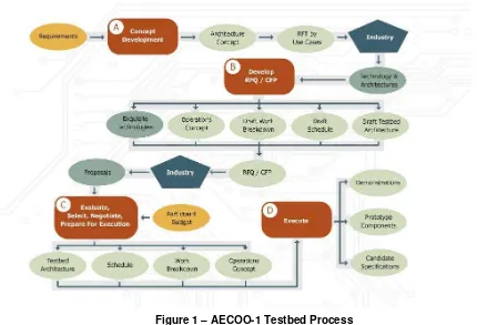
The AECOO-1 Testbed Execution Phase was preceded by a Concept Development Phase that included the release of a Request for Technology (RFT). Responses to the RFT from industry were used by the Sponsors to identify requirements for the RFQ. The overall process of the Testbed is shown in Figure 1. The dates for the various milestones were:
AECOO-1 Concept Development Phase:
Sponsor Meetings October 2007 - March 2008
RFQ development March 2008 – April 2008
RFQ response period May 2008 – June 2008
AECOO-1 Execution Phase*:
Kickoff Meeting 30 June – 3 July 2008
Interim Information Delivery Manual (IDM) Deliveries December 2008
Final Delivery January 2009
Interim Model View Definition (MVD) Deliveries March 2009
Final MVD Deliveries May 2009
AECOO-1 Demonstration March 2009
AECOO-1 2nd Demonstration May 2009
Web based Demo Release June 2009
*After the Kickoff Meeting, design, development and public review of IDMs, testing of AECOO-1 MVDs were conducted in a distributed fashion supported by the collaborative development resources of telecoms, a web portal, web collaboration tools, e-mail and weekly telephone conferences.
Figure 1 – AECOO-1 Testbed Process
1.3 Testbed Accomplishments
Ten sponsoring organizations defined Testbed requirements for AECOO-1. The sponsors‘ requirements were first documented in an RFT that was issued in February 2008. OGC received 20 AECOO industry responses and those responses were used as input to develop and publish the Request for Quotation/Call for Participation (RFQ/CFP) documents that were released by the OGC in May of 2008.
Four affiliated standards organizations provided pre RFQ/CFP advice, technical assistance. During the execution of the Testbed they were provided an opportunity for their membership to review interim documents in their various stages of drafting. Many of the four affiliated standards organizations regularly attended weekly conference calls for each technical thread.
27 organizations (including Sponsors and affiliated standards organizations) participated in some aspect of AECOO-1. Roles for organizations in AECOO-1 include sponsors,
participants and information architects, building architects, cost estimators, application providers and building energy analysts. Additionally, many organizations were observers, as provided for under the OGC‘s Interoperability Program‘s Testbed Processes and Procedures.
Energy Analysis Thread: Information Delivery Manual (IDM) for Building Performance and Energy Analysis (BPEA) 5 was developed and then used for development and
implementation of the companion Model View Definition (MVD)6. The MVD, based on the IFC standard 2.3 was then implemented in vendor IFC toolboxes within their respective solutions.
The IDM for Building Performance and Energy Analysis is available at: http://portal.opengeospatial.org/files/?artifact_id=29385
The MVD for Building Performance and Energy Analysis is available at: http://portal.opengeospatial.org/files/?artifact_id=34060 (for IFC 2.3) and http://portal.opengeospatial.org/files/?artifact_id=34059 (for Generic)
http://63.249.21.136/IAI-MVD/reporting/listMVDs.php?SRT=&MVD=BSA-002&DV=2 (online)
Concept Development, MVD and Implementation Guide for 2nd Level Space Boundaries are available at:
Space Boundary Concept and Implementation Guideline: http://portal.opengeospatial.org/files/?artifact_id=35079
Space Boundary MVD: http://portal.opengeospatial.org/files/?artifact_id=29375
Quantity Takeoff Thread: Information Delivery Manual (IDM) for Quantity Takeoff was developed and then used for development and implementation of the companion Model View Definition (MVD). The MVD, based on the IFC standard 2.3 was then implemented in vendor IFC toolboxes within their respective solutions.
The IDM for Quantity Takeoff is available at:
http://portal.opengeospatial.org/files/?artifact_id=32567
The MVD for Quantity Takeoff is available at:
http://portal.opengeospatial.org/files/?artifact_id=34062 (for IFC 2.3) and http://portal.opengeospatial.org/files/?artifact_id=34061 (for Generic)
http://63.249.21.136/IAI-MVD/reporting/listMVDs.php?SRT=&MVD=BSA-001&DV=2 (online)
Communications Project Delivery and Decision Support involved development of a series of user scenarios that enabled users and software providers to demonstrate the
accomplishments brought forward in the BPEA and QTO threads with a test building.
5
Information Delivery Manual defines the business processes and information flows for any topical issue involved with the design, construction and operation of a building. IDM specifies the process definition including the context and purpose of the exchange, the originating and consuming actors, and the information created and consumed. An approved IDM standard can become the basis of a contract between two parties for data interchange, thereby, treating information as an asset, enabling BIM-based methods, and regulating the information sharing between project participants.
6
Demonstrations and webcast: Two demonstrations were completed as part of the Testbed. The demonstration comprised a number of different energy and building performance
components of the ―test building‖, the results of energy analysis using EnergyPlus and the
effect those changes had on quantity of building materials and cost. The demonstrations used a number of different software vendor products that interchanged IFC information using existing commercial off-the-shelf software to perform the necessary calculations and results. The first demonstration was held in Washington at the National Building Museum in March of 2009. The second demonstration was via a webinar in May of 2009.
An on-line version of the webcast demonstration is available at: http://www.opengeospatial.org/pub/www/aecoo-1/index.html
Participants in the Demonstration included the following organizations:
Bentley
Stanford Center for Integrated Facility Engineering
Tokmo
2 Interoperability in the AEC Market
The AEC market is closely tied to global financial and real property markets. Since 2007 the AEC, real property and financial markets can be described as stressed and in disarray, however this has not impeded prospects for innovation in these large segments of the real economy. In fact, it is quite the opposite as we continue to witness a consistent and overarching characteristic of innovation in these fields of business, which is that work is increasingly focused on
information systems that can work together, or “interoperate”7.
Much has been written about the nature of and context for interoperability in the AEC market and many see the fractionated nature of the market to be too large a hurdle to overcome8. But
7
Interoperability can mean different things to different people and communities. Interoperability generally is a property referring to the ability of diverse information systems and organizations to work together (inter-operate). The term as used in this Report is a technical system engineering term as well as social, political, and organizational factors that impact system to system performance. A distinction must be drawn between interoperability and interoperation, with the former referring to creating a common fabric of interaction that everyone can connect to equally, and the latter being defined piecewise between particular systems (often through the creation of specific software adapters). It is our experience that it is far easier to do interoperation first, but it is interoperability that builds a real commodity with maximal benefits to the market.
8
again, when these doubts are parsed far enough we can begin to derive an interoperability
quotient, or IQ that technologists and practitioners alike can see from their distinct perspectives – that discrete components and systems, when conjoined with the ability to speak with each other, constructively influences the behavior of other systems and components in that market.
In the AEC market the tiny IQ has for some time increasingly impacted the economic value of information that can be used across the building lifecycle. The AEC market‘s low IQ indicates innovations that follow conventional norms are destined to underachieve and will continue fostering non-value added economic cost, lost productivity and lessened competitiveness. Information that plays well with other information across different and competing software applications is quickly becoming the new metric for innovation excellence, market take up and revenue growth.
Look no further than the Internet for inspiration about interoperable innovation. The misunderstood genius of the Internet is that interoperability makes ―networks of networks‖ possible. Standards that permit diverse data and applications to mingle creatively explain why
the Internet‘s influence as a multimedia, multifunctional and multidisciplinary environment for
innovation remains unsurpassed. Consider ―mash-ups‖ as a model: Google Maps can easily be mixed and mashed with property, seismic or epidemiological data to produce novel applications that might launch a company or an industry. Greater interoperability invites greater innovation – and vice versa. It is this characteristic that this Testbed and the combined efforts and
collaboration between bSa and OGC are addressing.
Over the last 10 years the concept of merging CAD, data management, requirements for
extending the shelf life of information and repurposing previously collected information helped to create what we now know to be Building Information Model (BIM) software. A BIM is a digital representation of physical and functional characteristics of a facility. As such it serves as a shared knowledge resource for information about a facility forming a reliable basis for decisions during its lifecycle from inception onward.
Many organizations over the past 5 years have jumped on the BIM bandwagon, and to those who did, suddenly realized the extent to which technology, business practice and process are jointly and materially impacted. The business opportunity space and production possibilities curves when employing BIM technologies are naturally pushed out, which implies that to receive the maximum benefit of the technology and new applications, the idea of paving over old cow paths does not suffice. Inherent in this mix of integrated application software and data sharing
capabilities is the opportunity for AEC businesses to not automate old and outmoded processes, but rather to evaluate and institute processes that increase efficiencies, productivity and add value. If BIM, through its technological advancement facilitates realizing process improvements, then reasonable economic and business judgments can be made about adoption.
2.1 Interoperability Standards in the BIM Marketplace
Users also desire to extend the value proposition of BIM beyond its role as simply a product – to see it and use it as a mechanism to carry out collaborative processes throughout the lifecycle of the facility. This value proposition covers business drivers, automated process capabilities and other network messaging and communications advantages. Currently, the opportunities to use BIM as a collaborative resource are largely dependent on project team members deciding which single vendor software to use for that project, and this decision customarily requires additional investments for transfer technology (along with related financial, training and support costs). Forcing AEC companies to change software on a project-by-project basis, and to continuously invest in new software and training negatively impacts the larger gains that BIM can offer and often means that businesses must continuously change the way in which they operate to accommodate the way that particular software works on a project-by-project basis.
So now the market is increasingly demanding that open information standards be more broadly applied to BIM technologies so that each partner in a project can comfortably adapt their internal processes, so that they can share project information across their chosen software and other
partner‘s chosen and possibly heterogeneous software platform(s), while preserving information
sustainability and fidelity across the lifecycle and minimizing their and their client‘s risk. This demand targets software providers to offer capabilities to exchange information seamlessly.
WhenBIM (and all its associated data categories and attributes) is successfully standardized across a set of numerous, but commonly defined data and information service levels and shown to work in run time conditions, the full utility of the technology as a collaborative tool and a facility lifecycle management tool can be realized.It involves gaining agreements about well-understood information exchanges, workflows, and procedures at not only the human level, but also the machines human use - where teams use and rely on repeatable, verifiable,
transparent, and sustainable information throughout the building lifecycle.
Thus, the basic premise of standards for BIM is to foster collaboration by different stakeholders at different phases of the lifecycle of a facility to insert, extract, update, or modify information in their software of choice and to support and reflect the roles of that stakeholder no matter what
provider‘s software is used by any member in a project team. When BIM software from any
provider can be thought of and used as a shared digital representation founded on open standards we then have achieved a level of interoperability like that suggested on page 7.
The National BIM Standard promotes the idea of the market undertaking and defining business requirements for standards that can result in interoperable software across the market. Software interoperability is seamless data exchange at the software level among diverse applications, each of which may have its own internal data structure. Interoperability is achieved by mapping parts
of each participating application‘s internal data structure to a standards-based data model and vice versa. If the employed standards-based data model is open, any application provider can participate in the mapping process and thus become interoperable with any other application
provider‘s offering that participated in the mapping. Interoperability eliminates the costly
practice of integrating every application (and version) with every other application (and version).
The NBIM Standard maintains that viable software interoperability in the capital facilities industry requires the acceptance of an open data model and the use of service interfaces
contained within provider‘s software to bring the capabilities of the data model to workflows
industry-wide means of communication and can be represented in its appropriate parts along the entire facility lifecycle, then every software application used across the lifecycle can become interoperable.
3 An Architecture for Interoperable Project Delivery
Given the mix of technical and business issues confronting the AEC market and the potential benefits interoperability through standards offers, the goal of AECOO-1 was to develop a process for standards development whereby more efficient sharing of building information between participants in a project team, and between the heterogeneous software products they use can be realized.
In the Concept Development stage of AECOO-1 (development of and comments on the RFT), we found that most of the industry that responded thought information sharing about buildings as an issue that involved transmitting complete information about a building between two design software packages. However, once a discussion on this topic was initiated during the kickoff meetings and later parts of the Testbed execution phase, we found that design-software-to-design-software was the least useful information sharing case to address. In the course of a design project, there is little need to share all aspects of the design between project participants. What is more important is to exchange relevant elements of the design between the lead
architecture firm or lead general contractor and subcontractors with specific expertise in areas such as lighting, energy usage, building cost, HVAC, circulation, etc.
3.1 Elements of BIM Standards for Interoperability
The design elements needed by these specialists are highly diverse, and so is the software they use to do their jobs. AECOO-1 found that there are few, if any, standard business practices
addressing fundamental information exchange requirements between the design team and area specialists. Technology cannot provide solutions until the business practices are firmly in place. This is why the information sharing challenge has been so difficult to solve, and many in the industry feel that technology standards efforts have not been as successful as they should.
Therefore, in order to make progress on the technology front, AECOO-1 also had to advance the process for developing business information practices associated with sponsor requirements.
The National Building Information Model Standard, Part 1, Version 1 provided us with the concepts of an Information Delivery Manual (IDM), which articulates what building information is required to accomplish a particular specialty analysis (e.g. lighting design, energy
performance, materials cost, etc.), and a Model View Definition (MVD), which is the smallest set of Industry Foundation Classes (IFCs) that are needed to express the information
requirements of a particular IDM. We found that specialists do their work to varying degrees of specificity depending on how fully developed the building model is at a point in time. In other words, the accuracy of the lighting study, energy analysis, or cost estimate changes as the design evolves.
AECOO-1 made two significant contributions in this area. First, we agreed upon a universal definition of project phases, and what level of detail was captured in building design at each project phase9. This was a critical first step to characterize what information could be expected to be present—and therefore what types of analyses could be performed—at a particular stage of design. Second, we brought into the discussion the groups responsible for standardizing nomenclature for building materials and other aspects of the design process such as the
Construction Specification Institute‘s OmniClass and Uniformat nomenclatures. Utilizing standard definitions of building materials, sizes, etc., is a prerequisite for creating standardized design interchange files in a standard data model for AEC – Industry Foundation Class (IFC) format. This aspect of standardization will need to occur often within the NBIMS process going forward. It is a conclusion implied in NBIMS Version 1, Part 1 and now verified by work done in AECOO-1.
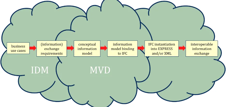
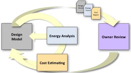
With our analysis of information flows from the business perspective of the sponsor‘s
requirements complete, we could then apply what was learned to the technology realm. The essential steps taken are graphically depicted in Figure 2. Following the figure we explore in more detail the actual activities that were undertaken.
Figure 2 – Interoperable information exchange relies on standardized business processes being codified in IDMs and MVDs
3.2 Interoperability Standards for Business Practices and Design Maturity
There is currently little standardization of the stages of design maturity during a project lifecycle, and therefore it is difficult to develop software that can work generically with any building. Therefore our first task of limiting the degrees of design freedom was to pick a project stage, and
9―Organizing the Development of a Building Information Model‖, Jim Bedrick, November, 2008 (unpublished) and
define fully what design information would be present in the IDM for the building model at any stage.
We chose to work at the conceptual design stage, as this is the point in time at which significant changes can still be made to positively impact cost, energy performance, and other key factors that inform final design. This choice resulted in the following definition of early, or conceptual design:
Level of Detail 200: Approximate geometry10
Design & Coordination (function / form / behavior): Generic elements shown in three dimensions (maximum size, purpose).
Authorized use for 4D Scheduling: Time-scaled, ordered appearance of detailed assemblies.
Authorized use for Cost Estimating: Estimated cost based on measurement of generic elements (e.g. generic interior wall).
Authorized use for Program Compliance: Specific room requirements.
Authorized use for Environmental (lighting, energy use, air movement
Analysis/Simulation): Conceptual design based on geometry and assumed system types.
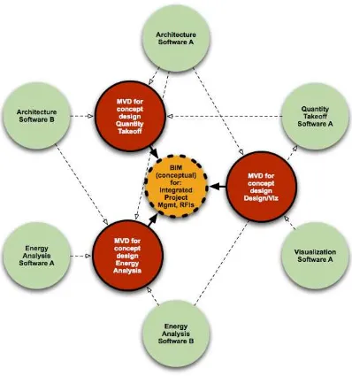
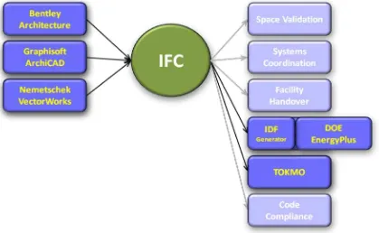
With this definition in place, we could then begin to define the information requirements for the IDMs that would support our two target business cases, energy performance and materials cost estimation. And then it became a simple matter to create the MVDs (see Figure 3 below) that defined what IFCs were needed to articulate the IDMs. The software vendors could then write code to translate their internal, proprietary building information models into interchangeable IFC models for energy analysis at the conceptual design stage, and materials cost estimation at the early design stage.
For perspective, creating the definition of conceptual design took about 2 project months, and the IDMs took 2-3 project months. The MVD creation took less than 2 weeks, and the actual
software development amongst the participating providers took under 2 months.
This underlines strongly the importance of having the industry agree to standardized business practices before we can have any hope of standardized information flows between software packages. This was by far the most important lesson of AECOO-1.
10From ―Organizing the Development of a Building Information Model‖, Jim Bedrick,
Figure 3 – MVDs relationship to information exchange between heterogeneous software and/or firms
4 AECOO-1 Threads and Work Areas
The development of the AECOO-1 Testbed was organized around the following 3 threads:
Building Performance and Energy Analysis (BPEA)
Quantity Takeoff for Cost Estimation (QTO)
4.1 IDM For Building Performance and Energy Analysis (BPEA)
Energy analysis is concerned with predicting the usage profile and cost of energy consumption within buildings. Conceptual design phase energy modeling is used to provide the design team with first order of magnitude feedback about the impact of various building configurations on annual energy performance. Conceptual phase energy modeling requires the designer to make assumptions for a wide of range of simulation input if information is not yet available. It takes into account as input data:
Building geometry including the layout and configuration of spaces,
Building orientation,
Building construction including the thermal properties of all construction elements including walls, floors, roofs/ceilings, windows, doors, and shading devices,
Building usage including functional use,
Internal loads and schedules for lighting, occupants, and equipment,
Heating, ventilating, and air conditioning (HVAC) system type and operating characteristics,
Space conditioning requirements,
Utility rates, and
Weather data.
The output results of energy analysis may include:
Assessment of the space and building energy performance for compliance with regulations and targets,
Overall estimate of the energy use by space and for the building and an overall estimate of the energy cost,
Time based simulation of the energy use of the building and time based estimate of utility costs, and
Lifecycle estimate of the energy use and cost for the building.
For the purposes of this process map, conceptual phase energy analysis is considered to include the assessment of heating and cooling demand within a building during peak periods.
Various types of analyses are within the scope of this process map, including:
Setting comfort criteria for spaces including minimum and maximum required indoor air temperatures (summer and winter), minimum fresh air requirements,
Heat loss/gain calculations using well defined analytical methods,
Energy performance rating system and/or energy code requirement compliance,
Analysis of energy consumption in meeting the building energy demands, and
Optimization of energy performance related to equipment or system type and related equipment/system performance characteristics considering lifecycle cost, environmental impact issues, and comfort aspects.
4.1.1 Cyclical Design
4.1.1.1 Conceptual Design
This is the analysis work undertaken during the programming and concept design stage of the project. It is about providing advice on the potential energy performance of a building and its systems to other design roles. The aim of this analysis is to have an impact on the overall building design, determine the feasibility of concepts in an energy context and to establish energy targets. Conceptual analysis may be undertaken in the absence of detailed geometric information about the building layout, though frequently general spatial layout is included during this stage. The designer is more concerned with relative performance values between the design options being considered, rather than absolute performance values. Though assumptions
typically must be made at this stage, maintaining consistent assumptions between the options being evaluated allows for relative performance to be evaluated.
4.1.1.2 Detailed Design
This is the analysis work undertaken during the schematic and design development stages of the project and assumes the availability of geometric and building system information for the design. The overall process is the same at each stage of work, the difference being simply about the extent of the information available and the level of certainty that can be applied to the
information. These factors impact the analysis methods used, which may range from relatively simple at the earlier design stages to detailed dynamic simulations at the later design stages.
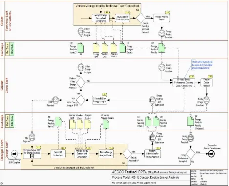
Figure 4 - Concept Design Phase Energy Analysis
4.1.2 IDM BPEA Information Exchanges
For Conceptual Design, the scope of the exchange of information is primarily about spaces with associated energy information and about proposed energy analysis zones. The purpose of the exchange requirement is to support the coordination of energy analysis requirements with general in building zoning and spacing requirements. Information requirements were defined as
―required‖ or ―optional‖. Data parameters and units of measurement were also defined. Also it was presumed that information exchanges took place between the role of Architect and a Mechanical Engineer and/or Energy Consultant.
The exchange requirement assumes that a building model is available from which relevant geometric information required for energy analysis can be derived. It is anticipated that the building model will provide context information about the project including units to be used, coordinate systems to be adopted and the direction of true north.
The building, its location, composition, overall shape and orientation
The shape and location of adjacent buildings to enable shading effects to be determined
Building stories within the building
Spatial configuration
Information that is provided by this exchange is to enhance the initial set of building model information including:
Space type and function identification with type data being obtained from a project space type library (which is in turn derived from an industry space type library). This data will drive assumptions on internal loads, conditioning requirements, etc.
Building elements construction type data with type data being obtained from a project construction type library (which is in turn derived from a industry construction type library). This data will provide information on the thermal characteristics of the building envelope and internal constructions.
Space boundaries that define the relation between spaces and building elements and the geometry that describes the space boundary connection.
Energy targets.
HVAC zoning, day lighting, and the use of photovoltaics.
For energy simulation and analysis, the scope is about the exchange of information related to energy demand, comfort, and annual energy consumption. The purpose of the exchange requirement is to enable coordination of energy analysis with other design roles based on the results of energy analysis and the ability to comply with set energy targets. The exchange requirement assumes that information about the building has been satisfied.
Information that is provided by this exchange requirement to includes:
Ventilation requirements,
Peak thermal loads,
Energy demand,
Annual energy consumption,
Utility rates, and
4.1.3 2nd Level Space Boundaries
At the Conceptual Design level of the building process as defined by IPD, the notion of space boundaries11 plays a role in energy analysis and quantity takeoff for cost estimation. There are defined three levels of space boundaries. The IDM developed in the BPEA Thread accounts for the first level. To provide for a more complete energy analysis and cost estimation, 2nd level space boundaries need to be calculated and work to define this component for conceptual design energy analysis was initiated in the Testbed.
4.1.3.1 Ist Level Space Boundaries
1st level space boundaries are the boundaries of a space defined by the surfaces of building elements bounding this space (physical space boundaries) or by virtual surfaces provided by an adjacent space with no dividing wall. Other characteristics that are part of a 1st level space boundary include:
1st level space boundaries do not consider any change of material in the bounding building elements, or different spaces/zones behind a wall or slab (floor or ceiling).
1st level space boundaries are differentiated in two ways: virtual or physical and internal or external.
1st level space boundaries form a closed shell around the space (so long as the space is completely enclosed) and include overlapping boundaries representing openings (filled or not) in the building elements (see implementers agreement below).
Implementers' Agreements --
Connection geometry for 1st level space boundaries may contain arcs (i.e. creating cylindrical surfaces), or polygons (i.e. creating extruded surfaces with orientation changes).
1st level space boundaries representing building elements (wall, slabs, columns, beams) do not include inner loops to create voids (e.g. for openings). Instead, there are separate 1st level space boundaries representing such openings (with or without contained doors and windows) -- which overlap and are coplanar with the space boundaries representing the host wall, slab, column, or beam.
11
4.1.3.2 2nd Level Space Boundaries
2nd level space boundaries still represent building elements that bound the space, but are more granular in that they are subdivided in any of the following cases:
Contained openings (with or without fillings like doors and windows)
Differences in materials and/or material assemblies (e.g. a wainscote or paneling on the lower portion of a wall).
Differences in spaces or zones on the other side of the building element (or virtual boundary) represented by the space boundary (e.g. two different spaces on the other side of a wall)
Differentiation between physical / virtual boundaries and internal / external boundaries is the same as for 1st level space boundaries.
2nd level space boundaries represent both sides of a heat transfer surface separated by the thickness of the building element. They can be used by thermal analysis software, but require, that the two adjacent surfaces are found and be combined to form a single heat transfer surface. This is required even where the two surfaces are of different length (e.g. non-rectangular wall connections and curved walls). See also 3rd level space boundaries.
2nd level space boundaries (including the 3rd level subtype described below) form a closed shell around the space (so long as the space is completely enclosed).
Implementers' Agreements --
The connection geometry of 2nd level space boundaries is restricted to planar surfaces only. This means that curved surfaces must be segmented.
The connection geometry of 2nd level space boundaries of walls/slabs/columns/beams and included openings/doors/windows do not overlap.
4.1.3.3 3rd Level Space Boundaries
3rd level space boundaries are special types of 2nd level space boundaries.
Type 3a - The most common type occurs where the element behind the boundary is a
building element, rather than a space or zone. For example: the end of a wall (wall butt) that divides two spaces on the other side of a wall.
Type 3b - a second type occurs where path based building elements intersect and overlap.
Type 3c - The third type occurs at non-orthogonal intersections of building elements where the two sides of the element have different lengths (e.g. angled wall connections). The extra length on one side or the other is defined to be a 3rd level space boundary.
3rd level space boundaries are typically ignored in heat transfer calculations for energy analysis because the transfer in these cases is negligible. Identification of such boundaries, as 3rd level, enables energy analysis software to ignore them.
The combination of 2nd level and 3rd level space boundaries form a closed shell around the space (so long as the space is completely enclosed).
Similar to 1st and 2nd level space boundaries, 3rd level space boundaries are a differentiation into virtual or physical and internal or external space boundaries.
The connection geometry of 3rd level space boundaries is restricted to planar surfaces only (same as for 2nd level). This means that curved surfaces must be segmented.
The connection geometry of 3rd level space boundaries of walls/slabs/columns/beams and included openings/doors/windows do not overlap (same as for 2nd level).
The Implementation Guide developed as part of this Testbed and completed under further USGSA guidance defines a stepwise approach for calculating space boundaries in buildings. A companion MVD provides software developers the means for implementation in software using IFC structured data.
4.1.4 MVD For Building Performance and Energy Analysis (BPEA)
Two MVD‘s were constructed for the BPEA IDM: a Generic and a Model View Binding for IFC 2.3 version along with an Implementation Guide.
The Generic Model View presents a collection of diagrams documenting the concepts based on the Exchange Requirements defined in the Information Delivery Manual (IDM). Note that generic concepts are documented and cataloged in the MVD coordination database for reuse across multiple MVDs.
The Model View Binding presents a collection of diagrams documenting how each generic concept will be represented in the IFC 2.3 information model schema to be used for the exchange Binding concepts are documented and cataloged in the MVD coordination database for reuse in multiple MVDs that will use the same schema for exchange for other MVDs using IFC 2.3.
The Implementation Guide provides instructions for programmers about how to implement specific concepts defined in the IDM and includes 3 parts:
Data instantiation diagrams - These diagrams document the exact information model entities that will be used to represent the concept (e.g. IfcObject) and parameters that must be used (e.g. property values),
Implementer agreements - Generally, these are agreed limitations to be used in this
representation of the concept where the underlying information model schema would allow a broader range of possibilities (e.g. agreement to use 3D facet geometry where the schema would allow for other types of 3D geometry).
Reference data - in many cases, an MVD will make use of existing industry standards to define value ranges (e.g. classification systems or enumerations defined in a reference standard). If the exchange only allows values from such a reference standard, a URL or information sufficient to access that reference standard will be provided.
4.2 IDM For Quantity Takeoff for Cost Estimation (QTO)
Quantity Take-Off is a precursor to completing a cost estimate to determine whether the design meets the project budget. In the early design (conceptual) design phase, quantities used for estimating are building or elemental level quantities as more detailed design information are not available. For example, the conceptual phase allows:
Walls and slabs by area,
Windows by count by size,
Structural system by facility area,
Heating system by facility area,
Cooling system by facility area,
The output of the quantity take-off may be the result of a report produced by the cost estimating application, which shows quantities. Other than a valid IFC file for use by cost estimating applications, the QTO process does not produce any output.
Throughout the estimating process the estimator typically communicates through various media with the design team, and perhaps the owner, to understand the design intent fully providing an appropriate estimate of building costs. Often, this post model output interaction among the various actors / roles is not captured formally. For Communication, Process and Decision (CPD) Making functionality, the BIM must be able to document the actors / roles interacting with the model. The various actors and roles mentioned specifically in the IDM are not indicative of all potential actors / roles at early design stages.
4.2.1 Cyclical Design
The process of outputting a quantity take-off is cyclical to match the design submittal requirements. It supports the cost estimating requirements to verify that the project design is within the established budget. The quantity take-off will have increasing complexity as the design progresses from early concept through final design.
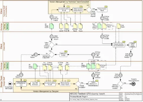
4.2.1.1 Conceptual
This is the analysis work undertaken during the programming and concept design stage of the project. It is about providing advice on the potential construction cost of a building to design roles and the client. The aim of this analysis is to determine the feasibility of concepts in a capital cost context. Conceptual analysis may be undertaken in the absence of detailed geometric information about the building layout, though frequently general spatial layout is included during this stage. Assumptions typically must be made at this stage, maintaining consistent assumptions between the options being evaluated allows for evaluation of relative cost performance.
4.2.1.2 Detailed
This is the analysis work undertaken during the schematic; design development and construction document stages of the project and assumes the availability of geometric and building system information for the design. The overall process is the same at each stage of work, the difference being simply about the extent of the information available and the level of certainty that can be applied to the information. These factors impact the analysis methods used, which may range from relatively simple area and elemental quantities at the earlier design stages to detailed quantity take-off at the later design stages.
Within this process map below, the conceptual design phase of the project is shown. The process map generically refers to the Design Team, Client – Client Staff and Client – Technical Staff or Consultants. For CPD integration, OmniClass Table 33 Disciplines provides a classification for the actors and OmniClass Table 34 Organizational Roles provides a classification for the roles. Any specific project team may require expanding the generic roles shown in process map to define in greater detail the actors and roles of the project.
Figure 5 – Concept Design Phase Quantity Take-Off
4.3 MVD for Quantity Takeoff for Cost Estimation
The same procedures as discussed in Section 4.1.4 were applied to the QTO IDM to develop the QTO MVDs – both generic as well as for IFC 2.3.
4.4 Communications Project Delivery and Decision Support (CPD)
5 Demonstrations and Webcast
Two demonstrations were completed as part of the AECOO-1 Testbed. The demonstrations
comprised a number of different energy and building performance components of the ―test building‖, the results of energy analysis using EnergyPlus and the effect those changes had on quantity of building materials and cost. The demonstrations used a number of different software vendor products that interchanged IFC information using existing commercial off-the-shelf software to perform the necessary calculations and results. The first demonstration was held in Washington at the National Building Museum in March of 2009. The second demonstration was via a webinar in May of 2009.
A streaming webcast of the May 28 AECOO-1 webinar is available for review: http://www.opengeospatial.org/pub/www/aecoo-1/index.html.
The webcast demonstrates results from the AECOO (Architecture, Engineering, Construction, Owner and Operator industry) Phase 1 Testbed.
The demonstrations focus on early design for a new building. The owner of the new building is interested to explore more energy efficient design alternatives and to have the building perform more cost effectively for the next 30 years.
The owner hires a design team composed of architecture firm and a general contractor, mechanical engineer and other professionals to conduct conceptual and early design services with the objective exploring these facets as part of the overall design process. In preliminary scoping meetings with the architect and general contractor team an established working budget was established. The building owner enters into an Integrated Project Delivery (IPD) contract with the architecture firm and general contractor to develop a schematic design package for the building. The architecture firm/general contractor is tasked to evaluate several design
alternatives, providing estimates of energy performance, quantities and cost related to those design alternatives. This input will allow the owner to calculate a return-on-investment for the project, and predict long-term building operating costs. Given that this is early design, the schematic design package and work to be undertake is to better understand cost and explore cost in terms of LEED building certification with relative performance options rather than absolute values
Figure 6 – AECOO-1 Demonstration flow of events
The demonstration highlighted four important conclusions of the Testbed:
Technology standards for interoperability provide a compelling approach for addressing owners' business requirements for better communication, process management, decision support and performance simulation of design alternatives;
Integrated Project Delivery (IPD) is realizable with interoperable technologies that enable faster, cheaper, and more effective information processes;
Project design teams can bring both energy and economic impact analysis upstream (i.e., earlier phases of design) using software that can seamlessly exchange data among different vendors' building information model (BIM) software applications, such as BIM authoring tools, quantity takeoff, value engineering, energy simulation, project and document management, and decision support; and
Multidisciplinary project teams that work together with data-sharing tools and common information models can indeed achieve better results faster than teams each working in their respective stovepipe application settings.
Figure 7 – IFC Data Exchange in Demonstration
The process and software of the demonstrations prove that the following are achievable today:
a) Quantitative cost and performance justification of design decisions early in the design process, resulting from parallel, partially automated and near-real-time cost estimating and building energy performance simulation;
b) Standardized process definition that indentifies tasks and information requirements for all participants and stakeholders, and unambiguously defines all data exchange requirements across the process;
c) Effective electronic information management and dissemination that serves all processes and project participants and stakeholders; and
d) Limited use of Industry Foundation Classes (IFC - ISO Standard 16739).
6 Lessons Learned & Recommendations
AECOO-1 provided bSa and OGC with a Petri dish in which to experiment with proven approaches to standards development that are recognized globally as efficient, capable and targeted and apply them to AEC market requirements. Given we were integrating a Testbed process designed for rapid development of web services standards to the AEC market we draw some conclusions for further discussion and follow-on testing by members of both organizations.
6.1 The Dimensions of BIM – Product, File and Conceptual
The belief that a Building Information Model is a way to organize information over the course of
that facility‘s lifecycle is accepted in the market. The belief that BIM can and should be the
for market efficiency is also accepted, but the idea that a BIM for any single project or portfolio of projects can be explicitly represented by s single data model, file type and/or single vendor software or suite of software packages is unrealistic. The AIA in its recent position statement12
about interoperability aptly describes today‘s situation:
Not all architects (or consultants, contractors, subcontractors, suppliers or owners) use the same software packages for their work, nor should they: each should use the best tool for the job in their particular business enterprise. But industry stakeholders do not work in a vacuum: they must share information in order to complete projects, and the amount of
necessary information sharing is increasing at a dramatic pace…
There are many dimensions to the data or information contained in software packages used in the AEC industry today. Begin by considering a building information model: every single object in a model has dozens or hundreds of discrete pieces of associated alphanumeric or geometric data. Multiply that by the hundreds or thousands of objects in the model. Then layer on possible other uses of the data beyond the model, like performance analysis of the design (structural, thermal, lighting, etc.), project management, estimating or facility management software, or sharing of the data between different BIM applications, and so on. Acknowledge that some of the data is time-sensitive and may change over the life of the model. The complexity of ensuring those hundreds of thousands of pieces of data be shared between packages in an accurate, consistent, complete and effective fashion, especially when one acknowledges the proprietary nature of the software packages, is mind-boggling.
The areas of expertise that flow into the design, development, and execution of a building project and/or a portfolio of properties are so diverse and distinctive that the industry must continue to plan for a scenario where firms use the best software for the particular job at hand, whether that job is design, energy utilization, project management, RFI tracking, code compliance, etc.
We now witness products being offered as BIM by individual vendors that offer users an array of one-stop, integrated offerings, often tied together by a proprietary data model(s) to support the full range of requirements identified above.
We also must acknowledge that due, in part to the lack of widely accepted and used application and data interoperability processes that are standardized across the marketplace, vendors and users have developed symbiotic relationships to satisfy business practice.
Finally, we need to acknowledge that a standard information model for building information classes is available. This standard, while still evolving to capture new requirements, has not been seen as an adoptable counter response to current vendor and user relationships and the perceived efficiencies of proprietary data structures. For the most part the standard is treated as more of an exotic framework for information exchange than as market driven best practice. The buildingSMART alliance and the NBIMS project exist to correct these market failures and raise awareness about the negative impacts and costs vendor lock-in creates throughout the market, and undertake necessary at the standards level for the market to gain the confidence and
12