SEMI-AUTOMATIC MODELLING OF BUILDING FAÇADES WITH SHAPE
GRAMMARS USING HISTORIC BUILDING INFORMATION MODELLING
C. Dore a, M. Murphy b
a Dublin Institute of Technology, Bolton Street Campus Dublin 1, Ireland, [email protected]
b Dublin Institute of Technology, Bolton Street Campus Dublin 1, Ireland, [email protected]
Commission V, WG V/4
KEY WORDS: HBIM, BIM, Laser Scanning, Parametric Modelling, Procedural Modelling, Shape Grammars, Architectural Modelling, Cultural Heritage, Semantic Modelling.
ABSTRACT:
This paper outlines a new approach for generating digital heritage models from laser scan or photogrammetric data using Historic Building Information Modelling (HBIM). HBIM is a plug-in for Building Information Modelling (BIM) software that uses parametric library objects and procedural modelling techniques to automate the modelling stage. The HBIM process involves a reverse engineering solution whereby parametric interactive objects representing architectural elements are mapped onto laser scan or photogrammetric survey data. A library of parametric architectural objects has been designed from historic manuscripts and architectural pattern books. These parametric objects were built using an embedded programming language within the ArchiCAD BIM software called Geometric Description Language (GDL). Procedural modelling techniques have been implemented with the same language to create a parametric building façade which automatically combines library objects based on architectural rules and proportions. Different configurations of the façade are controlled by user parameter adjustment. The automatically positioned elements of the façade can be subsequently refined using graphical editing while overlaying the model with orthographic imagery. Along with this semi-automatic method for generating façade models, manual plotting of library objects can also be used to generate a BIM model from survey data. After the 3D model has been completed conservation documents such as plans, sections, elevations and 3D views can be automatically generated for conservation projects.
1. INTRODUCTION
The digital recording of cultural heritage sites using laser scanning and photogrammetry has become a topic of great interest in the field of conservation and cultural heritage. Developments to laser scanning technology and photogrammetry now enable very efficient and accurate data to be collected to digitally preserve cultural heritage sites. International projects such as CyArk, 3D Icons and Scottish Ten are currently utilising these new technologies to digitally preserve important cultural heritage sites around the world.
Although data collection technologies are now very efficient and automated the processing of this data is still very time consuming. In many cases a point cloud resulting from a laser scan or image survey is used as the final product but the analysis and application of this data is limited primarily to visualisation and basic measurements. The generation of a geometric model allows for many more applications of survey data such as semantic and information modelling which enables complex analysis, management and visualisation of heritage data. Existing methods for generating accurate geometric heritage models are very time consuming and are generally carried out using a manual process. A fully automated process that uses techniques such as procedural modelling generally lacks the detail and accuracy that is required for heritage applications.
The approach presented in this paper uses a semi-automatic technique which maintains a high level of accuracy and is also very efficient compared with manual methods. The methodology combines parametric modelling and procedural
modelling techniques based on architectural knowledge. These developments are packaged as a plug-in for Building Information Modelling (BIM) software which is called Historic Building Information Modelling (HBIM). HBIM contains an interactive library of parametric architectural objects that have been designed from architectural data. These parametric objects were coded using the Geometric Description Language (GDL) which is an embedded programming language within the ArchiCAD BIM software.
Procedural modelling techniques have been used to create a parametric façade that can automatically combine library objects using classical proportions and rules. This tool provides users with full control over the object with parametric and graphical editing to manipulate the object. Façades and elements are automatically generated using GDL and then adjusted with laser and image-based survey data resulting in a semi-automatic process.
The final product is an object orientated, semantic BIM model which is high in geometric detail and accuracy. This model can be used to automatically produce conservation documents such as elevations, plans, sections and 3D views. The rich geometric model can also be textured with true orthographic images to provide a photo-realism model for applications such as tourism, gaming and education. Finally the BIM model can be used as an information system to store information about conservation projects such as time and cost of renovations along with other historical material relating to the heritage site.
International Archives of the Photogrammetry, Remote Sensing and Spatial Information Sciences, Volume XL-5/W1, 2013 3D-ARCH 2013 - 3D Virtual Reconstruction and Visualization of Complex Architectures, 25 – 26 February 2013, Trento, Italy
1.1 Overview of Paper
Section two firstly contains a review of existing literature related to this work. Section three describes in more detail the design of the parametric library objects for HBIM. Section four then describes the design of a parametric façade using procedural modelling techniques. Next the plotting of HBIM objects and facades to survey data is described in section five. Finally section six contains the conclusions and future work to be carried out.
2. RELATED WORK
The use of Building Information Modelling (BIM) software in the cultural heritage field has many advantages such as semantic object orientated modelling which allows for the classification of heritage objects, automatic lists of objects and material and automated conservation documents. BIM allows for accurate modelling using interactive parametric objects that contain information about the objects and their relationships with other objects. One of the current limitations of BIM in the cultural heritage field is the lack of parametric library objects within BIM software that could be used for historical buildings or heritage sites (Boeykens 2011). The HBIM plug-in presented in this paper intends to fill this current gap and contains a library of parametric objects that can be used to accurately model classical style architecture for heritage applications.
Other work by Boeykens et al. (2012), Fai et al. (2011) and Pauwels et al. (2008) have also concentrated on modelling heritage sites using BIM software. These papers however have concentrated on using existing BIM tools to develop models of heritage sites and are therefore limited with the models and documentation that can be created. Pauwels et al. (2008) describe an approach called Architectural Information Modelling which uses BIM software to document a heritage site which contains geometric data along with appended historical information such as photographs, scanned documents or research material. Fai et al. 2011 adopt a similar approach which links heritage information to a BIM model but also includes documentation related to tangible and intangible heritage. Boeykens et al. (2012) use BIM software to create a reconstruction of the Vinohrady Synagogue in Prague which was demolished in 1951. Existing tools in ArchiCAD’s BIM software such as the Shell tool are used to try and create organic geometry that is needed for the heritage site. The authors of this paper note that the BIM software used was almost completely focussed on contemporary buildings and that more specific tools are needed for historical reconstructions.
Very little work has been carried out in the development of parametric historical objects that can be used for heritage applications. Work by Chevrier et al. (2010) is one of the few examples of parametric modelling for historical buildings. In this work a library of parametric objects is created using the MEL scripting language for Maya software from Autodesk. These models are not suitable for BIM software though and their primary application is documentation and visualisation.
A similar technique is adopted by Thaller et al. (2011) where parametric and procedural modelling techniques are used to create eight parametric building models. These are not designed for heritage applications but as a planning tool to analyse buildings as they change from design stage to construction stages. Their approach involved using a scripting language for parametric design called Generative Modelling Language (GML). Procedural modelling techniques using shape grammars, derived from formal grammars are applied with the GML scripting language to create the parametric building models. The resulting building models can be manipulated interactively with respect to dimensions, number of floors and
other parameters. These models are not designed for a detailed representation of buildings but as a rough model to analyse the impact of changes in the building on the energy footprint.
Automatic methods for generating geometric models such as procedural modelling have traditionally been used in applications such as film and gaming where content can be randomly generated based on rules and algorithms. The use of shape grammars in procedural modelling has gained a lot of interest and is now being used to generate content for architectural modelling. Shape grammars originally introduced by Stiny et al. (1972) are derived from formal grammars and consist of a set of basic vocabulary shapes (terminals and non-terminals) and a set of production rules to transform these shapes to create 3D content. A shape grammar called CGA Shape (Muller et al. 2006) has been developed for the commercial software CityEngine from ESRI. This shape grammar is designed for procedural modelling of buildings and cities. CityEngine software provides users with tools to create 3D content from scripts using this shape grammar. With this software it is possible to procedurally generate buildings from 2D footprints and other GIS datasets for modelling existing buildings and cities.
Most procedural modelling applications require users to code rules in a grammar to create a specific model. This text based approach restricts users with little computer science background. Work by Lipp et al. (2008) has concentrated on creating an interactive visual editing tool for shape grammars to create rules from scratch without the need for text file editing. This makes automated approaches for generating 3D content much more accessible and does not require advanced users to create scripts to code rules.
Another approach (Müller et al. 2007) uses CGA shape grammar for automatic modelling of building facades from a single rectified image. This method automatically detects the façade structure using mutual information and symmetry detection to divide the façade into floors and tiles. Further tile refinement is automatically carried out using edge detection to split tiles into smaller regions using a subdivision concept from procedural modelling which creates a hierarchy of elements. This is used to automatically detect window positions, ledges and window sills. Finally 3D objects from a library of architectural elements are matched to the subdivided façade to add windows and other architectural elements. Depth for different sections of the façade is added manually and the computed façade can be exported as shape grammar rules in the CGA Shape Grammar. This method shows how procedural modelling techniques can be applied to existing buildings. This method works well for urban environments where facades contain a lot of repetition and symmetry can be easily detected. However less repetitive facades with a lot of architectural detail may be problematic for this automatic method.
CGA shape grammar but have been implemented using the Generative Modelling Language (GML).
Approaches such as procedural modelling with shape grammars have many advantages such as automatic generation, great flexibility for variation, object hierarchy, scalable geometric representation and data handling of large models. However a big disadvantage of these methods for heritage applications is that they are inefficient for generating smaller complex geometric detail. Muller et al. (2006), state that manual methods are used instead of procedural modelling techniques to create detailed elements such as roof bricks, capitals and window grills. The accuracy of automatic techniques such as edge detection from images and object recognition is also not suitable for producing accurate models needed for conservation documentation. Applications for procedural modelling of existing facades (Müller et al. 2007) are primarily visualisation and the aim is to automatically create a geometric model that “looks like a plausible interpretation of the input image” (Müller et al. 2007). For heritage documentation a more precise and accurate model is often required.
Combing procedural modelling techniques with parametric modelling makes use of the advantages of procedural modelling combined with very detailed parametric objects that can be used to model complex geometric detail such as capitals and decorative architectural elements. Using a semi-automatic approach also allows for very precise modelling of existing architecture from laser scan or image data.
3. HBIM LIBRARY CREATION
This section describes a summary of the methodology for creating the library of interactive parametric architectural objects that are mapped to laser scan and image data. Previous work such as Murphy et al. (2013) describe this process in more detail.
3.1 Geometric Description Language
The parametric library objects were created using the programming language GDL, a language for creating parametric objects within ArchiCAD BIM software. This syntax of this language is similar to that of BASIC programming language. GDL provides a large number of functions for creating 3D parametric objects using primitive shapes such as blocks, spheres, cones and ellipses or by generating shapes from 2D outlines. GDL uses coordinate transformation commands stored in a stack to position multiple objects relative to each other. GDL allows for graphical editing of parameters, complex Boolean operations, various control statements and the use of mathematical functions in creating parametric objects. Also provided is the ability to script a specific user interface for objects and their parameters (Graphisoft 2011).
3.2 Architectural Rules
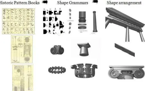
The design and detail for the parametric objects are based on architectural manuscripts ranging from Vitruvius to Palladio to the architectural pattern books of the eighteenth century. The architecture of the renaissance introduced and documented advanced scientific rules for the production of architectural elements, which support the design of parametric models. The use of historic data introduces the opportunity to develop detail behind the object’s surface concerning its methods of construction and material makeup.
3.3 Shape Rules and Parametric Design
Using GDL the classical elements detailed in the pattern books are re-produced using a design framework based on parametric
rules and shape rules. Objects are scripted with parameters making them dynamic objects that can be reused. A bottom-up approach is adopted which starts with the smallest building objects such as ornamental mouldings and profiles. These uniform objects are created from a shape vocabulary of 2D shapes that allow for all configurations of the classical orders (Figure 1). Shape rules are used to transform these 2D shapes to represent classical mouldings and profiles. Non-uniform and organic shapes are developed in GDL through a series of procedures attempting to maximise parametric content of the objects (Figure 1). These shapes are stored as individual parametric objects or combined to make larger objects such as columns, pediments, walls, windows or roofs.
Figure 1. Historic data and shape grammars for classical orders.
4. PROCEDURAL FAÇADE GENERATION
A parametric façade has been developed using shape grammars, a concept from procedural modelling. Using shape grammar rules it is possible to incorporate architectural rules and proportions into the procedurally generated façade. Various configurations of the façade can be altered with parameter adjustment. Parameters for the structure of a façade include “number of stories”, “windows to left of door”, windows to right of door” and “wall width”. Further parameters allow users to choose existing library objects which are automatically positioned on a façade including windows, block wall detail and other architectural elements. The precise position of elements can be subsequently refined using graphical editing if required which is described in Section 5.
4.1 Architectural Rules
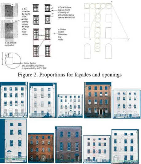
Similar to the design of the library objects the parametric façade also uses architectural knowledge to assist with the digital reconstruction process. Rules and proportions outlined in pattern books relating to classical building facades are used. The proportioning of a façade is determined by the geometry of the window openings, which is expressed in Figure 2 by the relationship between circles of the same radius. The top windows are made up of a single circle, in the next set of windows intersecting circles and finally in the lower set of windows the circles are placed one on top of each other. Using a parameter for the window width or circle diameter the height and position of windows can be calculated with these proportions. These proportions are evident in most classical buildings, however alterations to buildings can obscure of remove some of the original façade proportions. Alterations of a façade over time can inlcude removal or enlarging of brick walls, window and door openings and parapets. After testing the classical proportions on a variety of surveyed facades (Figure 3) the most suitable proportions and parameters were adopted as seen in Figure 4.
International Archives of the Photogrammetry, Remote Sensing and Spatial Information Sciences, Volume XL-5/W1, 2013 3D-ARCH 2013 - 3D Virtual Reconstruction and Visualization of Complex Architectures, 25 – 26 February 2013, Trento, Italy
Figure 2. Proportions for façades and openings
Figure 3. Testing classical proportions using orthographic imagery from surveyed classical buildings.
Figure 4. Proportions and parameters used for design of parametric façade.
4.2 Shape Grammars
Shape grammars are a very suitable approach to architectural modelling as they allow models to be created from a vocabulary of basic shapes and set of replacement rules where a shape can be replaced or altered by transformations. These principles facilitate the encoding of classical architectural rules and proportions which also use grammars or vocabularies for architectural elements and rules to combine these basic shapes.
A standard shape grammar introduced by Stiny et al. (1972) can be defined as {N, Σ, P, S} where N and Σ represent a finite set of nonterminal and terminal shapes (the vocabulary), P are a set of production rules and S is the starting seed. Terminal shapes are the basic vocabulary elements and can be a collection of points, lines, planes areas or solids. Nonterminal shapes are markers or boxes that are used to guide the terminal shapes during generation process and control the scope and position of shapes. The production process begins with nonterminal shapes which are replaced by terminal shapes when rules are applied. The production process terminates when no more rules can be applied and all nonterminal shapes have been removed. Production rules are applied in the form A→B where A and B and shapes. When a rule is applied the shape on the left hand
side is replaced by a new shape on the right hand side of the rule.
Stiny (1977) also introduced the concept of a parametric shape grammar. This type of shape grammar differs from standard shape grammars in that it contains shape rules defined in terms of parameterized shapes. A parametric shape grammar can be defined as {S, L, R, I, T} where S is a finite set of shapes, L is a finite set of labelled points, R is a finite set of shape rules, I is an initial shape and T is a set of transformations. The main differences are that nonterminal shapes are replaced by labelled points or parameters that are associated with shapes. Euclidean transformations have also been added which can be a translation, rotation, scale or mirror. Shape rules are applied to a shape with an assignment of real values to the parameters and with additional transformations as required.
4.2.1 Shape Grammar for Parametric Facade
The concepts of a parametric shape grammar are adopted for this approach. This section describes the principles of the shape grammar used to create the parametric façade. The coding of this grammar is discussed in Section 4.3. The grammar used contains the various elements of a parametric shape grammar defined by Stiny (1977) which include the elements {S, L, R, I, T}, previously described. The initial shape {I} is made up of a labelled solid shape as seen in Figure 5. This shape contains four labelled points as parameters which control the size and shape of the object. An additional parameter also defines a thickness which converts the 2D shape into a 3D solid shape.
Figure 5. Initial shape {I} for shape grammar
The basic elements that make up the vocabulary of shapes {S} can be seen in Figure 6. Shapes include two wall tiles; one wall tile TW which contains a window opening and surrounding wall. A second wall tile TD is used as a panel containing a door opening. Additional library objects relating to a door and door case such as columns are pediments are linked with this shape TD. Other shapes include library objects for windows and a simple block that is used to create geometry for a block wall. Additional library objects described in the previous sections are also used in conjunction with these shapes in Figure 6.
The shape rules {R} used are shown in Table 1. The concepts for many of these rules are based on the CGA shape grammar, (Muller et al. 2006). Additional custom rules have also been developed for incorporating the architectural rules described in Section 4.1. Table 1 shows the initial shape on the left hand side of each rule and the resulting shape on the right hand side after the rule has been applied. Each rule is applied with an assignment of real values to parameters for shapes and transformations if required such as translations, rotations, scaling or mirroring.
Figure 6. Basic shape vocabulary elements {S} for shape grammar
TD TW W BL
Table 1. Shape Rules {R} for Shape Grammar
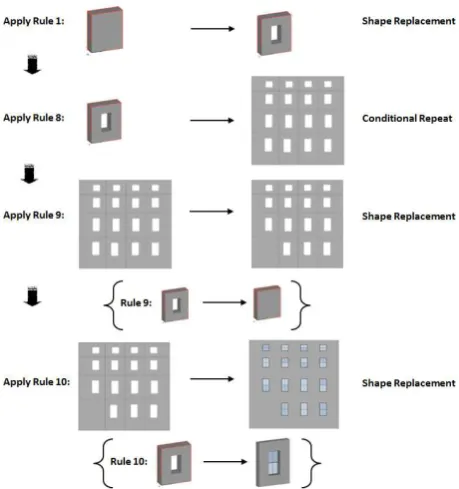
Rule 1: replaces the initial shape {I} with the shape TW by adding an opening to the solid shape. The new shape TW has new parameters to define the coordinates of the opening. Rule 2: repeats a shape along the x-axis. Parameters are used to control the number of repetitions or a distance which specifies the number of repetitions.
Rule 3: is similar to rule 2 but repeats shapes along the y-axis. Rule 4: splits a shape along the x-axis into smaller or separate shapes. Parameters control the positions and number of splits. Rule 5: is similar to rule 4 but splits shapes in the y-axis. Rule 6: splits a shape in the x-axis and removes one of the segments.
Rule 7: splits a shape in the y-axis and removes one of the segments.
Rule 8: conditional repeat (described below).
Rule 9: replaces a window tile TW with a door tile TD. Rule 10: adds a selected window W from the library to a window tile TW.
Rule 8 is the main rule that creates the façade structure. This rule repeats the wall tile TW in both x and y directions based on various parameter settings and architectural rules. This method contrasts to the concepts adopted in the CGA shape grammar where a façade is split into smaller tiles. This rule repeats the input shape in the y direction for the first column, and then moves to the second column and so on until all tiles have been placed for the specified parameters. Parameters for the “number of floors” and “number of columns” control the number of repeated instances to be placed in each column and floor. The input for this rule is the shape TW and coordinates for this shape which is an assignment of the shapes parameters.
The coordinates assigned to the shape TW are required to change on each iteration to allow for different tile dimension based on the classical proportions. The coordinates for each iteration of the wall tile are automatically calculated and inputted into the shape after applying the classical proportions described in section 4.1. Theses proportions are calculated from user defined parameters for “window width” and “distance
between ground and first floor windows”. After these proportions are calculated the coordinates of each tile and window opening are returned and stored in four arrays. When the shape TW is repeated with this rule the coordinates for each iteration are obtained from these four arrays resulting in a façade with classically proportioned window openings.
Figure 7 shows the order and application of the rules shown in Table 1 to create the basic parametric façade. The application of rule 9 adds a door tile TD. The position of this is obtained from a user defined parameter “windows to left of door”. Figure 8 shows another application of the rules in Table 1 used to create a parametric block wall that can be combined with the parametric wall façade. Using Boolean operations the window openings are removed from the block wall when combined with the existing façade. Parameters allow the user to add a block wall to the ground floor or all floors of the façade. Parameters of the block wall enable the user to change the individual block size, mortar spacing and texture. Figure 12 and Figure 13 show the basic parametric façade with block wall detail and windows automatically combined.
Figure 7. Application of shape rules specified in Table 1.
4.3 Implementation of Shape Grammar with GDL
Various programs and languages have been used to implement shape grammars to generate shapes from a grammar. Examples include the CGA Shape grammar implemented in ESRI’s CityEngine software (Muller et al. 2006). Other shape grammars have been implemented using the Generative Modelling Language (GML) (Hohmann et al. 2009) (Thaller et al. 2011). The shape grammar described in the previous section has been implemented using the Geometric Description Language (GDL). Although designed for parametric design, because of its powerful capabilities GDL can also be used to generate shapes from a shape grammar. To date this language has not been used to implement shape grammars. Using the GDL language with shape grammars enables the advantages of automated procedural modelling to be incorporated within a BIM environment.
International Archives of the Photogrammetry, Remote Sensing and Spatial Information Sciences, Volume XL-5/W1, 2013 3D-ARCH 2013 - 3D Virtual Reconstruction and Visualization of Complex Architectures, 25 – 26 February 2013, Trento, Italy
Figure 8. Application of shape rules specified in Table 1.
4.3.1 Suitability of GDL for Shape Grammars
GDL as described in Section 3.1 has many complex functions for generating parametric 3D content. Similar to the BASIC programming language, GDL structures content using executive scripts and subroutines. Parts of code can also be stored separately as macro objects which can be called from a script. This structure facilitates the implementation of a shape grammar as rules can be stored as individual macros which can be called from a script and applied to vocabulary shapes which are stored in individual subroutines. GDL also uses coordinate transformations stored in a stack to transform and position objects relative to each other. This includes the functions ADD, ROT and MUL which are used to apply translations, rotations and scaling. These transformations are very suitable for the Euclidean transformations which are part of a parametric shape grammar concept introduced by Stiny (1977).
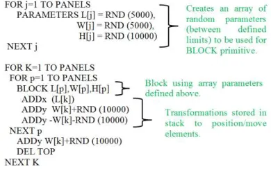
Many procedural modelling techniques apply variation using rules chosen randomly along with random parameter assignment within rules. This allows for the creation of large scenes to be procedurally generated with a lot of variation. Within GDL these concept can be replicated using the RND function to generate a random value between defined constraints. This can be used to assign random parameter values and also to choose rules (stored as macro objects) to be applied randomly. Figure 9 shows an example of this where a very short piece of code can automatically generate 3D content for a large scene (Figure 10) using random parameters values and transformations. This is created from one vocabulary shape (block) and one rule applied to this shape. A user parameter can control the number of iterations or repetitions of this shape.
Figure 9. GDL code which randomly generates 3D content shown in Figure 10.
Figure 10. Automatically generated 3D content with GDL using random parameters and transformations.
4.3.2 Encoding Shape Grammar with GDL
Within GDL the initial shape for the shape grammar (Figure 5) is coded using a function cPRSIM. This is coded by defining the shape using coordinates on the x-y plane and specifying a height or thickness. The shape can be rotated using the transformation command ROT to lift it off the x-y plane. The coordinates are inputted as parameters which can alter the shape and size of the object. This same command is used to create the vocabulary shapes TW, TD and BL. Figure 11 shows the GDL code for the shape TW which is stored in a subroutine and called when a rule is being applied to this shape.
Figure 11. GDL code for vocabulary shape TW.
Loop commands are used in rules 2 and 3 (Table 1) to repeat shapes in a certain direction. Various cut commands such as CUTPLANE or CUTPOLY are used for rules 4 to 7 with Boolean operations such as SUBTRACT for removing segments. Rule 8 uses loop commands with transformations to move to the required column. IF statements are used to control the number of iterations with parameters for the “number of floors” and “number of columns”. Parameters definingthe coordinates of the shape TW are stored in arrays and programmed to input the correct set of coordinates into the shape depending on the position of the current iteration. Rule 9 replaces a shape with another shape and rule 10 adds a new shape to an existing shape such as adding a window to a wall tile. Figure 12 and Figure 13 show various parametric façades generated in GDL using the described shape grammar.
Coordinates of tile as parameters
Coordinates of
window opening as parameters
Figure 12. Parametric façade with classically proportioned window openings and block wall detail.
5. PLOTTING TO SURVEY DATA
Once the BIM geometry has been automatically generated for either library objects or an entire façade the next stage involves accurately mapping this to survey data for existing buildings. The parametric façade already has elements positioned with parameters and classical proportions. Because all building won’t conform exactly to these classical proportions and rules the position of certain elements may need to be refined. This is carried out using graphical editing while overlaying the generated façade with 2D orthographic imagery obtained from laser scan or image modelling methods. This semi-automatic method along with a manual method of mapping library objects is discussed in this section.
5.1 Semi-Automatic Plotting of Facades
Using GDL it is possible to create interactive objects that can move in a defined constrained way. This is possible by creating the object with parameters that are defined relative to the rest of the object. With GDL hotspots are used to define points that can be graphically edited based on a parametric constraint. This method is used to enable graphical editing of individual points for the parametric façade.
5.1.1 Issues with Graphical Editing from Shape Grammars The main problem with implementing this method of graphical editing with shape grammars is that it requires local modifications to be applied to shapes that have many instances and globally defined parameters. For example if a shape such as a window has many instances repeated throughout the façade then modifying a parameter will update all placed instances of the shape. To overcome this, the ability to apply a local modification that does not affect other instances is required. A second problem exists after local modifications are made, these edits can be lost if the model is regenerated from the grammar. For example modifying a global parameter such as window width will reapply the classical proportions using the shape rules resulting in a loss of local edits. This requires local edits to be stored persistently so they will not be lost. Both of these problems have been outlined in other work by Lipp, et al. (2008). The authors of this work have developed solutions to these problems by introducing instance locators in the object hierarchy for local control. Using these instance locators it is
possible to persistently store edits externally that will not be lost when a grammar is regenerated.
For this approach the problem of local modifications has been overcome by storing multiple assignments of a parameter value using arrays and on each iteration of a loop that places a new occurrence of an object, a new parameter values is assigned from the array. This can be seen in Figure 13 where a vocabulary shape for a window is defined once but repeated for many occurrences with different parameter assignment such as its parameter for the “window height” on each occurrence. The second issues relating to persistence and loss of modifications with this approach is not a significant problem as only a small
number of parameter modifications require the model to be regenerated from its rule set. The rules that do require the complete model to be regenerated are relating to the initial classical proportions to the façade. These proportions are applied as constraints to parameters so in order to later modify these parameters the initial constraints must be disabled. Re-enabling these constraints will result in loss of edits as the classical proportions will be reapplied to the façade. Other modifications to the structure of a façade such as changing the number of stories or columns does not result in loss of edits as parameters for individual tiles are stored persistently in arrays so are retained even after the model is regenerated.
5.1.2 Graphical Editing of Parametric Façade
Figure 14 shows the parametric façade with editable points marked. A user simply selects a point or element to graphically edit and moves it to the required position. This can be carried out in 3D or in 2D while overlaid with orthographic imagery. In order to provide efficient editing certain hotspot points have been coded to move multiple parameters at once. For example hotpots between floors can be used to move all tiles and windows on a floor simultaneously. This greatly speeds up the editing as all windows on a floor or column can be edited together. Individual elements such as a window corner can be individually modified also to provide very accurate results. As an element of a façade is modified all linked elements are also updated automatically as seen in Figure 15 where graphically editing a window opening automatically updates the combined block wall which calculates the required subtractions or additions using Boolean operations.
Figure 14. Wall Façade with editable points (hotspots) used for graphical editing (left) and wall façade overlaid with
orthographic image (right).
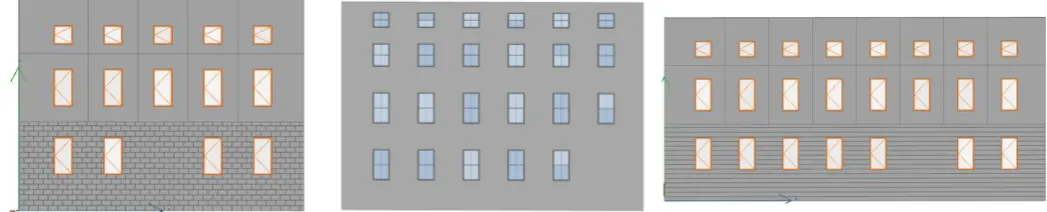
Figure 13. Various configurations of classical parametric façades automatically generated using shape grammars. International Archives of the Photogrammetry, Remote Sensing and Spatial Information Sciences, Volume XL-5/W1, 2013 3D-ARCH 2013 - 3D Virtual Reconstruction and Visualization of Complex Architectures, 25 – 26 February 2013, Trento, Italy
Figure 15. Graphically editing window opening which automatically updates linked elements such as block wall.
5.2 Manual Plotting
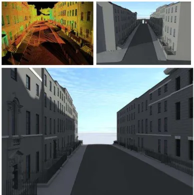
Along with the methods for semi-automatically plotting building facades, manual plotting methods can also be used with existing HBIM library objects. The approach used with HBIM is to map the objects in 2D onto segmented point clouds and orthographic images in elevation, plan and section. Before placing a library object in HBIM the default parameters of the object can be edited, changing the object’s shape, size or other properties to correspond with the survey data. When library objects are brought into HBIM they are first positioned in plan using orthographic imagery or cut sections through the point cloud. The height of the object is specified by a parameter for its formation level. Objects are then more precisely positioned in front and side elevation from further orthographic imagery and cut sections. Figure 16 shows an example of a point cloud and subsequent HBIM model created using the parametric library objects and procedural façade described in this paper.
Figure 16. Point cloud and subsequent HBIM model created using parametric library objects and procedural façade.
6. CONCLUSION AND FUTURE WORK
This paper has presented a new approach for semi-automatic modelling of building facades from laser scan or image data using Historic Building Information Modelling. This methodology uses a shape grammar to create a parametric façade that automatically positions elements based on architectural rules and proportions. Users have full control over the façade with parametric and graphical editing to manipulate the object without the need for text file editing of code. Both global and local modifications are possible to refine automatically positioned elements that don’t match the survey data. This method allows for accurate and efficient modelling of existing buildings from laser scan or image data. This approach incorporates parametric modelling techniques with procedural modelling techniques by combining detailed parametric objects with shape grammars. This work is still in progress and more work is currently being carried out to integrate more parametric library objects with the procedural façade. The shape grammar and parametric library objects have been implemented with the Geometric Description Language for ArchiCAD BIM software. This enables the tools developed to utilise the full benefits of
BIM software which include automated construction or conservation documents, semantic object orientated objects based on IFC sematic classes, automatic lists of objects and material and the ability to add and link additional information to the model. Future work in this project will concentrate on extending the shape grammar for procedural modelling of entire buildings with GDL using HBIM library objects.
7. REFERENCES
Boeykens, S 2011, 'Using 3D Design software, BIM and game engines for architectural historical reconstruction ', paper presented to CAAD Futures 2011, Liège, Belgium, 6-8 July 2011.
Boeykens, S, Himpe, C & Martens, B 2012, 'A Case Study of Using BIM in Historical Reconstruction - The Vinohrady synagogue in Prague', paper presented to The 30th International Conference on Education and research in Computing Aided Architectural Design in Europe, Prague, Czech Republic, 12-14 September 2012.
Chevrier, C, Charbonneau, N, Grussenmeyer, P & Perrin, J -P 2010, 'Parametric Documenting of Built Heritage: 3D Virtual Reconstruction of Architectural Details', International Journal of Architectural Computing, vol. 08, no. 02, pp. 131-45.
Fai, S, Graham, K, Duckworth, T, Wood, N & Attar, R 2011, 'Building Information Modelling and Heritage Documentation', paper presented to XXIII CIPA International Symposium, Prague, Czech Republic, 12th-16th September,.
Graphisoft 2011, GDL Reference Guide.
Hohmann, B, Krispel, U, Havemann, S & Fellner, D 2009, 'CityFit - High-quality urban reconstructions by fitting shape grammars to images and derived textured point clouds', paper presented to 3D-ARCH 2009 - 3D Virtual Reconstruction and Visualization of Complex Architectures, Trento, Italy, 25-28 February 2009.
Lipp, M, Wonka, P & Wimmer, M 2008, 'Interactive Visual editing of Grammars for Procedural Architecture', ACM Transactions on Graphics, vol. 27, no. 3, p. 1. Muller, P, Wonka, P, Haegler, S, Ulmer, A & Gool, LV 2006,
'Procedural Modeling of Buildings', ACM
Transactions on Graphics, vol. 25, pp. 614-23. Murphy, M, Govern, EM & Pavia, S 2013, 'Historic Building
Information Modelling – Adding intelligence to laser and image based surveys of European classical architecture', ISPRS Journal of Photogrammetry and Remote Sensing, vol. ISSN 0924-2716.
Müller, P, Zeng, G, Wonka, P & Gool, LV 2007, 'Image-based Procedural Modeling of Facades', ACM Trans. Graph., vol. 26, no. ACM, p. 85.
Pauwels, P, Verstraeten, R, Meyer, RD & Campenhout, JV 2008, Architectural Information Modelling for Virtual Heritage Application, Digital Heritage -- Proceedings of the 14th International Conference on Virtual Systems and Multimedia, Archaeolingua. Stiny, G 1977, 'Ice-ray: a note on the generation of Chinese
lattice designs', Environment and Planning B, vol. 4(1), pp. 88-98.
Stiny, G & Gips, J 1972, 'Shape Grammars and the Generative Specification of Painting and Sculpture', The Best Computer Papers of 1971, pp. 125-35.
Thaller, W, Krispel, U, Havemann, S, Redi, I, Redi, A & Fellner, DW 2011, 'Developing Parametric Building Models - The Gandis Use Case', paper presented to 4th International Workshop 3D-ARCH 2011, "3D Virtual Reconstruction and Visualisation of Complex Architectures", Trento, Italy, 2-4 March.