Cisco Networks
Engineers’ Handbook of Routing,
Switching, and Security with
IOS, NX-OS, and ASA
—
Chris Carthern
Will Wilson
Noel Rivera
Richard Bedwell
Cisco Networks
Engineers’ Handbook of Routing,
Switching, and Security with IOS,
NX-OS, and ASA
NX-OS, and ASA
Copyright © 2015 by Chris Carthern, William Wilson, Richard Bedwell, and Noel Rivera
This work is subject to copyright. All rights are reserved by the Publisher, whether the whole or part of the material is concerned, specifically the rights of translation, reprinting, reuse of illustrations, recitation, broadcasting, reproduction on microfilms or in any other physical way, and transmission or information storage and retrieval, electronic adaptation, computer software, or by similar or dissimilar methodology now known or hereafter developed. Exempted from this legal reservation are brief excerpts in connection with reviews or scholarly analysis or material supplied specifically for the purpose of being entered and executed on a computer system, for exclusive use by the purchaser of the work. Duplication of this publication or parts thereof is permitted only under the provisions of the Copyright Law of the Publisher’s location, in its current version, and permission for use must always be obtained from Springer. Permissions for use may be obtained through RightsLink at the Copyright Clearance Center. Violations are liable to prosecution under the respective Copyright Law.
ISBN-13 (pbk): 978-1-4842-0860-1
ISBN-13 (electronic): 978-1-4842-0859-5
Trademarked names, logos, and images may appear in this book. Rather than use a trademark symbol with every occurrence of a trademarked name, logo, or image we use the names, logos, and images only in an editorial fashion and to the benefit of the trademark owner, with no intention of infringement of the trademark.
The use in this publication of trade names, trademarks, service marks, and similar terms, even if they are not identified as such, is not to be taken as an expression of opinion as to whether or not they are subject to proprietary rights.
While the advice and information in this book are believed to be true and accurate at the date of publication, neither the authors nor the editors nor the publisher can accept any legal responsibility for any errors or omissions that may be made. The publisher makes no warranty, express or implied, with respect to the material contained herein.
Managing Director: Welmoed Spahr Acquisitions Editor: Robert Hutchinson Developmental Editor: Douglas Pundick Technical Reviewer: Evan Kwisnek
Editorial Board: Steve Anglin, Pramilla Balan, Louise Corrigan, James DeWolf, Jonathan Gennick, Robert Hutchinson, Celestin Suresh John, Michelle Lowman, James Markham, Susan McDermott, Matthew Moodie, Jeffrey Pepper, Douglas Pundick, Ben Renow-Clarke, Gwenan Spearing
Coordinating Editor: Rita Fernando Copy Editor: Kim Burton-Weisman Compositor: SPi Global
Indexer: SPi Global
Distributed to the book trade worldwide by Springer Science+Business Media New York,
233 Spring Street, 6th Floor, New York, NY 10013. Phone 1-800-SPRINGER, fax (201) 348-4505, e-mail [email protected], or visit www.springer.com. Apress Media, LLC is a California LLC and the sole member (owner) is Springer Science + Business Media Finance Inc (SSBM Finance Inc). SSBM Finance Inc is a Delaware corporation.
For information on translations, please e-mail [email protected], or visit www.apress.com.
Contents at a Glance
About the Authors ...
xxv
About the Technical Reviewer ...
xxvii
Acknowledgments ...
xxix
Introduction ...
xxxi
■
Chapter 1: Introduction to Practical Networking...
1
■
Chapter 2: The Physical Medium ...
23
■
Chapter 3: Data Link Layer ...
35
■
Chapter 4: The Network Layer with IP ...
49
■
Chapter 5: Intermediate LAN Switching ...
69
■
Chapter 6: Routing ...
93
■
Chapter 7: VLANs, Trunking, VTP, and MSTP ...
149
■
Chapter 8: Basic Switch and Router Troubleshooting ...
187
■
Chapter 9: Network Address Translation and Dynamic
Host Configuration Protocol ...
255
■
Chapter 10: Management Plane ...
273
■
Chapter 11: Data Plane ...
297
■
Chapter 12: Control Plane ...
319
■
Chapter 13: Introduction to Availability ...
383
■
Chapter 14: Advanced Switching ...
407
■
Chapter 16: Advanced Security ...
481
■
Chapter 17: Advanced Troubleshooting ...
555
■
Chapter 18: Effective Network Management ...
623
■
Chapter 19: Data Center and NX-OS ...
649
■
Chapter 20: Wireless LAN (WLAN) ...
689
■
Chapter 21: ASA and IDS ...
715
■
Chapter 22: Introduction to Network Penetration Testing ...
759
■
Chapter 23: Multiprotocol Label Switching ...
773
Contents
About the Authors ...
xxv
About the Technical Reviewer ...
xxvii
Acknowledgments ...
xxix
Introduction ...
xxxi
■
Chapter 1: Introduction to Practical Networking...
1
Tools of the Trade ...
1
Open Systems Interconnection (OSI) Model ...
2
Physical Layer ...
5
Data Link Layer ...
6
Network Layer ...
7
Transport Layer ...
7
Connection-Oriented ...
8
Session Layer ...
8
Presentation Layer ...
9
Application Layer ...
9
The OSI Model: Bringing It All Together...
9
TCP/IP Protocol ...
11
TCP/IP Application Layer ...
12
TCP/IP Transport Layer ...
12
TCP/IP Internet Layer ...
13
TCP/IP Network Interface Layer ...
14
Reliability ...
15
Port Numbers ...
18
Types of Networks ...
19
Personal Area Network ...
19
Local Area Network ...
19
Campus Area Network ...
19
Metropolitan Area Network ...
19
Wide Area Network ...
20
Wireless Wide Area Network ...
20
Virtual Private Network ...
. 20
Hierarchical Internetwork Model ...
21
Summary ...
22
■
Chapter 2: The Physical Medium ...
23
The Physical Medium ...
23
Standards ...
24
Cables...
25
Twisted Pair Cable ...
. 25
Coaxial Cable ...
. 27
Fiber Optical Cabling ...
. 28
Fiber Optic Transmission Rates ...
. 28
Wireless Communication ...
. 29
The Ethernet ...
29
Duplex ...
30
Time-Division Duplexing ...
31
Frequency-Division Duplexing ...
31
Autonegotiation ...
31
Unidirectional Link Detection ...
32
Common Issues ...
33
■
Chapter 3: Data Link Layer ...
35
Protocols ...
35
The Address Resolution Protocol (ARP) ...
35
The Reverse Address Resolution Protocol (RARP) ...
38
Link Layer Functions ...
38
Framing ...
38
Addressing ...
38
Synchronizing ...
39
Flow Control...
39
Link Layer Discovery Protocol (LLDP) ...
40
Class of Endpoints ...
40
LLDP Benefits ...
41
Cisco Discovery Protocol (CDP) ...
44
Summary ...
48
■
Chapter 4: The Network Layer with IP ...
49
IP Addressing (Public vs. Private) ...
50
Public ...
50
Private ...
50
IPv4 ...
50
Class A ...
51
Class B ...
51
Class C ...
51
IPv4 Packet Header...
52
IPv6 ...
53
IPv6 Packet Header...
54
Classless Inter-Domain Routing ...
55
Subnetting ...
55
Subnet Mask ...
56
Subnetting Exercises ...
62
Subnetting Exercise Answers ...
65
Exercise 1 Answers ...
65
Exercise 2 Answers ...
66
Exercise 3 Answers ...
67
Exercise 4 Answers ...
67
Summary ...
68
■
Chapter 5: Intermediate LAN Switching ...
69
Configuration Help ...
72
Displaying the Running Configuration ...
73
Configuring the Router ...
74
Switching ...
76
EtherChannel ...
76
Spanning Tree Protocol ...
81
Why Do You Need STP?...
81
How STP Works ...
81
Bridge Protocol Data Units ...
81
Rapid Spanning Tree Protocol ...
. 82
Exercises ...
86
Exercise Answers ...
87
Exercise 1 ...
87
Exercise 2 ...
88
Exercise 3 ...
89
Summary ...
91
■
Chapter 6: Routing ...
93
Static Routing ...
93
The Process of Routing ...
. 94
Dynamic Routing Protocols ...
100
Distance-Vector Routing Protocol ...
100
Link-State Routing Protocol ...
101
Hybrid Routing Protocol ...
102
RIP ...
102
Configuration ...
103
Authentication ...
104
EIGRP ...
108
OSPF ...
114
Configuring OSPF ...
117
Router ID ...
123
BGP ...
123
BGP Configuration ...
124
Administrative Distance ...
129
RIP ...
129
EIGRP ...
130
OSPF ...
130
BGP ...
131
Exercises ...
131
Exercise Answers ...
134
Exercise 1 ...
. 134
Exercise 2 ...
136
Exercise 3 ...
138
Exercise 4 ...
141
Exercise 5 ...
146
■
Chapter 7: VLANs, Trunking, VTP, and MSTP ...
149
Virtual Logical Network (VLAN)...
149
VLAN Configuration ...
150
Trunking ...
155
Trunk Configuration ...
157
Routing Between VLANs ...
159
Routing VLANs Configurations ...
160
VLAN Trunking Protocol ...
162
VTP Modes ...
162
Multiple Spanning Tree Protocol ...
165
MSTP Configuration ...
167
Exercises ...
172
Exercise Answers ...
176
Exercise 1 ...
176
Exercise 2 ...
180
Exercise 3 ...
181
Summary ...
185
■
Chapter 8: Basic Switch and Router Troubleshooting ...
187
Troubleshooting 101 ...
187
Documenting Your Network ...
187
First Things First: Identify the Problem ...
188
Top-Down Approach ...
189
Bottom-Up Approach ...
190
Physical Medium and Ethernet ...
191
VLANs and Trunks ...
194
EtherChannel ...
198
VTP ...
200
Routing ...
205
Static Routing ...
205
Dynamic Routing ...
208
RIP ...
208
EIGRP ...
212
OSPF ...
219
BGP ...
227
Exercises ...
232
Exercise Answers ...
239
Exercise 1 ...
239
Exercise 2 ...
240
Exercise 3 ...
243
Exercise 4 ...
246
Exercise 5 ...
248
Exercise 6 ...
250
Exercise 7 ...
252
Summary ...
254
■
Chapter 9: Network Address Translation and Dynamic
Host Configuration Protocol ...
255
NAT ...
255
Static Nat ...
256
Dynamic NAT ...
257
Port Address Translation (PAT) ...
258
DHCP ...
261
DHCP Process ...
261
Setting up a Router As a DHCP Client ...
262
Setting up a Router to Send a Request to a DHCP Server ...
262
Setting up a Router As a DHCP Server ...
263
Exercise Answers ...
267
Exercise 1 ...
267
Exercise 2 ...
268
Exercise 3 ...
269
Exercise 4 ...
270
Summary ...
272
■
Chapter 10: Management Plane ...
273
The Management Plane Defined ...
273
Authentication and Authorization Basics ...
274
User Accounts ...
276
Password Recovery ...
277
Banners ...
279
Management Sessions ...
280
Telnet ...
280
SSH ...
281
Console and Auxiliary Lines ...
282
Disabling Services ...
283
Disabled Services ...
283
Disabled Services on Interfaces ...
284
Authentication, Authorization, and Accounting (AAA) ...
284
RADIUS ...
285
TACACS+...
287
Monitoring/Logging ...
288
Simple Network Management Protocol ...
288
syslog ...
291
Exercises ...
293
Exercise Answers ...
295
Exercise 1 ...
295
■
Chapter 11: Data Plane ...
297
Traffic Protocols ...
297
Filters and Introduction to Data Plane Security ...
299
State Machines ...
302
Stateful Protocols ...
306
Stateless Protocols ...
310
NetFlow and sFlow ...
311
Exercises ...
315
Summary ...
317
■
Chapter 12: Control Plane ...
319
Layer 2 ...
319
Routing Protocols ...
322
Interior Gateway Protocols ...
323
Exterior Gateway Protocols...
. 340
Protocol Independent Multicasting ...
347
Domain Name System ...
351
Network Time Protocol ...
354
Exercises ...
358
Preliminary Work ...
358
OSPF ...
360
BGP ...
361
NTP ...
361
EIGRP Named Mode with Authentication ...
362
Multicast ...
362
Exercise Answers ...
362
Preliminary Configuration ...
362
OSPF ...
366
NTP ...
375
EIGRP Name Mode with Authentication ...
377
Multicast ...
378
Summary ...
381
■
Chapter 13: Introduction to Availability ...
383
High Availability ...
383
First Hop Redundancy Protocol (FHRP) ...
384
HSRP ...
384
VRRP ...
388
GLBP ...
390
Multilinks ...
394
Availability Exercises ...
396
Exercise Answers ...
399
Exercise 1 ...
399
Exercise 2 ...
401
Exercise 3 ...
402
Exercise 4 ...
405
Summary ...
406
■
Chapter 14: Advanced Switching ...
407
Port Security ...
407
DHCP Snooping ...
409
HSRP ...
409
VRRP ...
411
Server Load Balancing (SLB) ...
414
TFTP ...
415
IOS Switch Upgrade ...
416
Password Recovery ...
416
Advanced Switching Exercises...
421
Advanced Switching Exercise Answers ...
422
Exercise 1 ...
422
Exercise 2 ...
423
Summary ...
423
■
Chapter 15: Advanced Routing ...
425
Policy-Based Routing Using Route Maps ...
425
Redistribution ...
428
RIP Redistribution Overview ...
429
EIGRP Redistribution Overview ...
429
OSPF Redistribution Overview ...
431
BGP Redistribution Overview ...
432
Avoiding Loops and Suboptimal Routing ...
433
EIGRP ...
434
Unicast ...
435
Summarization ...
435
Load Balancing ...
436
EIGRP Stub ...
436
Traffic Engineering with EIGRP ...
436
Authentication ...
437
Multiarea and Advanced OSPF ...
438
Summarization ...
440
OSPF Stub ...
440
Cost Manipulation ...
441
OSPF Virtual Link ...
441
Authentication ...
443
BGP ...
443
Address Families ...
443
Peer Groups and Templates ...
444
Next Hop Issues with iBGP ...
448
Anycast ...
448
Traffic Engineering with BGP ...
449
IPv6 Routing ...
451
EIGRPv6 ...
453
OSPFv3 ...
456
GRE Tunnels ...
458
BGP Issues ...
460
IPSec ...
461
IOU8 Configuration ...
463
IOU9 Configuration ...
465
Advanced Routing Exercises ...
466
Exercise 1: EIGRP and OSFP Redistribution ...
466
Exercise 2: GRE and IPSEC ...
467
Exercise 3: BGP ...
467
Exercise 4: IPv6 OSPF and EIGRP Redistribution ...
468
Exercise Answers ...
469
Exercise 1 ...
469
Exercise 2 ...
470
Exercise 3 ...
473
Exercise 4 ...
476
Summary ...
479
■
Chapter 16: Advanced Security ...
481
Owning Your Spanning Tree ...
482
Securing Your Trunks and Ports ...
499
802.1x (dot1x) ...
506
Examples Using OpenSSL to Generate Signed Certificates ...
520
CDP and LLDP ...
523
Private VLANs ...
536
Use Case ...
536
Promiscuous vs. Community vs. Isolated ...
537
Configuration ...
537
Using Extended ACLs, PACL, and VACL ...
539
VACL...
540
PACL ...
541
AAA ...
542
Use Case ...
542
Console ...
542
AUX Port ...
542
VTY Ports ...
543
Local Authentication and Authorization ...
543
Remote AAA (TACACS, RADIUS)...
543
Configuration ...
543
Advanced Security Exercises ...
550
Exercise 1: Extended ACL Exercises ...
. 550
Exercise 2: AAA Exercises ...
550
Exercise Answers ...
551
Exercise 1 ...
551
Exercise 2 ...
552
Summary ...
553
■
Chapter 17: Advanced Troubleshooting ...
555
Access Control List ...
555
VACL ...
558
PACL ...
559
Network Address Translation ...
559
Static NAT ...
560
Dynamic NAT ...
565
HSRP, VRRP, and GLBP ...
571
HSRP ...
572
VRRP ...
573
EIGRP ...
576
OSPF ...
580
BGP ...
583
Neighbor Relationships...
583
Missing Prefixes ...
585
Route Redistribution ...
590
EIGRP ...
590
OSPF ...
593
GRE Tunnels ...
596
Recursive Routing...
599
IPSec ...
599
IPv6 ...
602
Advanced Troubleshooting Exercises ...
611
Exercise Answers ...
616
Exercise 1 ...
616
Exercise 2 ...
618
Summary ...
621
■
Chapter 18: Effective Network Management ...
623
Logs ...
623
Simple Network Management Protocol ...
625
Service Level Agreements and Embedded Event Manager ...
631
sFlow and Netflow Tools ...
634
Intrusion Detection and Prevention Systems ...
638
Exercises ...
644
syslog ...
644
SNMP ...
644
Service Policy ...
645
Exercise Answers ...
645
Initial Configuration ...
645
syslog ...
646
SNMP ...
647
Service Policy ...
647
Summary ...
648
■
Chapter 19: Data Center and NX-OS ...
649
NX-OS ...
649
SSH and Telnet ...
651
User Accounts ...
. 652
VLAN ...
653
Configuring a Non-Routed VLAN ...
653
Configuring a VLAN As a Routed Switched Virtual Interface (SVI)...
653
VLAN Trunking Protocol ...
654
EIGRP ...
655
OSPF ...
659
BGP ...
663
Port Channels ...
665
Port Profiles ...
671
FEX ...
671
First Hop Redundancy Protocols ...
672
HSRP ...
672
VRRP ...
674
Network Virtualization ...
679
Virtual Device Context (VDC) ...
679
Virtual Port Channel (vPC) ...
680
Virtual Routing and Forwarding (VRF) Lite ...
681
NX-OS Exercise ...
685
Exercise Answer ...
686
Summary ...
688
■
Chapter 20: Wireless LAN (WLAN) ...
689
Wireless LANs (WLANs) ...
689
Wireless Standards ...
689
Wireless Components ...
690
Wireless Access Points ...
690
Wireless Controllers/Switches ...
690
Wireless Bridges ...
691
Wireless Repeaters ...
691
Wireless Antennas ...
691
Installing a WLAN ...
692
Wireless Site Survey ...
692
Range, Signal Strength, and Performance ...
693
Access Point Installation...
693
Access Point Configuration ...
694
WLAN Controller Installation ...
701
WLAN Controller Configuration ...
702
Security ...
707
Encryption and Authentication ...
707
Threats and Vulnerabilities ...
712
Wireless Exercise ...
713
Exercise Answers ...
713
■
Chapter 21: ASA and IDS ...
715
Testing Policies in Safe Environment ...
715
Initial Setup ...
716
Baseline the Network ...
725
Access Rules ...
731
Open Services ...
733
Anti-Spoofing ...
735
Fragmentation ...
737
Designing Service Policies ...
738
Passwords ...
739
■
Chapter 22: Introduction to Network Penetration Testing ...
759
Overview ...
759
Reconnaissance and Scanning ...
760
Vulnerability Assessment ...
763
Exploitation ...
767
Summary ...
772
■
Chapter 23: Multiprotocol Label Switching ...
773
Multiprotocol Label Switching Basics ...
773
Label Protocols ...
780
LDP Security and Best Practices ...
782
LDP Verification ...
786
MPLS VPN ...
788
Site-to-Site VPN ...
790
Shared Extranet ...
800
IPv6 over MPLS ...
806
Exercises ...
809
MPLS Backbone ...
810
Site-to-Site VPN ...
811
Leak to Customer B ...
811
Tunneling IPv6 ...
812
Exercise Answers ...
812
MPLS Backbone ...
813
Site-to-Site VPN ...
815
Leak to Customer B ...
818
Tunneling IPv6 ...
821
Summary ...
823
About the Authors
Chris Carthern (CCNP, CISSP) is a senior network engineer for the US Department of Defense. He is responsible for analyzing, designing, installing, configuring, maintaining, and repairing Cisco network infrastructure and application components, and for training and mentoring junior network engineers and preparing them for Cisco and CISSP certification exams. Carthern took his BS (honors) in computer science from Morehouse College and his MS in system engineering from the University of Maryland, Baltimore County (UMBC). He holds the following certifications: Cisco Certified Network Professional (CCNP), Certified Information Systems Security Professional (CISSP), CompTIA Security+, Brocade Certified Network Professional (BNCP), and ITIL v3.
William Wilson is a senior network engineer with 20 years of information technology experience. He is responsible for design, implementation, and maintenance of campus, WAN, and data center networks. William completed his undergraduate degree in Mathematics at University of Colorado, and obtained his MS and doctoral degrees in computer science from Colorado Technical University. He holds the following certifications: Cisco Certified Network Professional (CCNP), Cisco Certified Security Professional (CCSP), Certified Information Systems Security Professional (CISSP), CompTIA Security+, CompTIA A+, Certified Ethical Hacker (CEH), Microsoft Certified Systems Engineer (MCSE), Microsoft Certified Solutions Developer (MCSD), and Microsoft Certified Database Administrator (MCDBA). He passed the written portion of the CCIE certification and he is studying for the practical lab component.
About the Technical Reviewer
Acknowledgments
First, I would like to thank God for giving me the strength to complete the large task of writing a book. I would like to thank my loving wife, Genna, for the support while I spent countless hours writing this book. Many thanks also must go out to my co-authors for contributing to this work. Thanks must also be given to my parents, Taylor and Lisa, and sister, Breanna, for all the support you have given me and importance you have placed on higher education. To my colleague Kelvin “KJ” Johnson, thanks for testing my labs and providing feedback, and Dieter, thanks for the support. And to my technical reviewer, Evan Kwisnek, thank you for all the feedback on the content and exercises in the book; this book is better because of your diligent reviews. I would like to send a big thanks to my publisher, Apress, for taking my book proposal and guiding me through the writing process. For anyone I missed, thank you all for your support and helping me become a better engineer! Last but not least, I can’t forget Bowman.
Introduction
Do you want to become a better and more efficient network engineer? If you answered yes to that question, then Cisco Networks: Engineers’ Handbook of Routing, Switching, and Security with IOS, NX-OS, and ASA is for you. You will learn intermediate and advanced concepts of configuring, managing, and troubleshooting Cisco networks. Most chapters provide examples of configuring network devices and include exercises to reinforce the concepts that were covered. Each exercise also includes a step-by-step solution to the question, in the event you are not able to solve the problem.
This book is meant to be a configuration guide, not geared toward certifications, with an emphasis on solving real-world day-to-day challenges. Although this book is not focused on certifications, readers will learn the skills and concepts needed to pass Cisco CCENT, CCNA, and CCNP certification exams. Readers will also learn how to build and configure at-home labs using virtual machines and lab exercises to practice advanced Cisco commands.
This book differentiates itself from other Cisco books on the market by approaching network security from a hacker’s perspective. Not only does it provide network security recommendations but it teaches you how to use such tools as oclHashcat, Loki, Burp Suite, Scapy, Metasploit, and Kali to actually test the security concepts learned. The book combines a black-hat perspective that most network engineers have a disconnect with unless they are network penetration testers. Cisco Networks not only discusses security but also provides the how-to on using the black-hat tools for network security testing.
The goal of this book is to eliminate the need to have three or four books in your library. The book covers commands related to Cisco IOS, NX-OS for datacenter installations, and ASA configurations. If you are a network engineer, or aspiring to be one, this book is for you.
Introduction to Practical
Networking
Chapter 1 begins by discussing a few of the tools that you will use throughout the book. Next, we cover the beloved OSI model and discuss how it relates to networking. We talk about all seven layers of the OSI model. Then we move on to the TCP/IP model and show its relation to the OSI model. We end the chapter discussing well-known port numbers, the different types of networks, and Cisco’s hierarchical internetwork model.
So you want to become a good network engineer? Let us give you some advice: do not believe that you know everything there is to know about networking. No matter what certifications or years of experience you have, there will always be gaps in knowledge, and people that know or have experienced issues that you may not have. Troubleshoot issues systematically from layer to layer. Use your resources—such as this book! You can never have too many resources at your disposal in your toolbox. Do not be afraid to ask for help. Do not be ashamed because you cannot resolve a problem. That is why we have teams of engineers. Everyone has their expertise and we must use each to our advantage. Remember when dealing with networks it is always better to have a second pair of eyes and another brain to help resolve issues quickly. This will help you save time and stop you from working in circles. You want to know how you can become a good network engineer? Start by reading this book and complete the lab exercises to reinforce what you have learned. The rest will come from experience on the job. Practice makes perfect!
Tools of the Trade
How do you practice in a lab setting? We all cannot go around buying our own network equipment and creating our own lab environment. The best thing is to configure and test with real equipment that can be bought secondhand on eBay. There are also many tools that can be used to simulate routers in a virtual environment. Because all of the devices are virtual, they come with limitations on what you can do with them. These limitations are discussed in Appendix A.
To become proficient at anything, practice is needed, and to be efficient, tools are needed. Our tool of choice to practice and simulate network topologies is the Graphical Network Simulator (GNS3), and our tool of choice to peek into the network packets is Wireshark. There are other tools that you can use, but we found these two to be the easiest and most straightforward. Just in case you want to look at other options, a quick Internet search for “network simulators” and “network sniffers” will provide a list of the available alternatives to GNS3 and Wireshark, respectively.
Cisco Packet Tracer is a network simulation tool that allows you to simulate the configuring, operation, and troubleshooting of network devices. For more information, visit https://www.netacad.com/web/ about-us/cisco-packet-tracer.
Cisco Virtual Internet Routing Lab (VIRL) is a network simulation tool that uses virtual machines running the same IOS as Cisco’s routers and switches. It allows you to configure and test real-world networks using IOS, IOS XE, IOS XR, and NX-OS. For more information, visit http://virl.cisco.com.
Open Systems Interconnection (OSI) Model
Before we define the OSI model, let’s talk about why it should be important to you. First, the OSI model is something you should understand and not just gloss over. We understand that the thought of the model can put people to sleep if you have not had that morning coffee yet, but it can be an immense aid if you know how protocols communicate with one another and how each layer operates with another. How is it that a PC can communicate using so many protocols, or why can many companies create technologies that interoperate with others’ technologies? Even though you may be a network engineer and think that you will only work at layers 2 and 3, it is important to know and understand how all the layers of OSI function. This will aid you when it comes to troubleshooting layer 1 and many of the applications you may use to monitor your devices. If you know the OSI model, you can create your own troubleshooting methodology. Gaining the theory and the hands-on practice allows you to know which layers to troubleshoot after you have tested a cable, as data gets closer to the device of the end user. Now that you know how important it is, let’s talk about the OSI model.
The OSI model is a conceptual model, also known as the seven-layer model, which was established by the International Organization for Standardization (ISO) and the International Telecommunication Union— Telecommunication Standardization Sector (ITU-T) to develop commonality in function and interface between communication protocols.
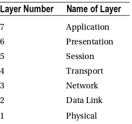
It is important to note that the OSI model is not a set rule but merely a reference guide for vendors to follow so that their products can interface with one another. The seven layers can be seen in Table 1-1. The purpose of the model is to allow multivendor networks to interoperate independently and only require knowledge of interfaces between layers.
Table 1-1. OSI Model
Layer Number
Name of Layer
7 Application
6 Presentation
5 Session
4 Transport
3 Network
2 Data Link
1 Physical
The physical, data link, network, and transport layers define how data is transmitted from source to destination. The lower layers are important in the processing of intermediary devices such as routers. Table 1-1 shows the seven layers. The layers will be discussed in more detail later in the chapter.
The following are some of the advantages of the OSI model:
• It standardizes the industry and defines what occurs at each layer of the model. • By standardizing network components, it allows many vendors to develop products
that can interoperate.
• It breaks the network communication processes into simpler and smaller components, allowing easier development, troubleshooting, and design.
• Problems in one layer will be isolated to that layer during development, in most cases.
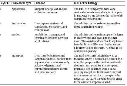
The applications layer interfaces with users using a computer or other devices, and is also responsible for communications between users or hosts. The bottom four layers—physical, data link, network and transport—define how data is transported through the physical medium, as well as through network devices (i.e., routers). The upper three layers—session, presentation and application—know nothing about networking. Table 1-2 shows the functions of each layer in the OSI model.
Table 1-2. Function of Layers in the OSI Model
Layer #
OSI Model Layer
Function
CEO Letter Analogy
7 Application Support for application and end-user processes
The CEO of a company in New York decides he needs to send a letter to a peer in Los Angeles. He dictates the letter to his administrative assistant.
6 Presentation Data representation and translation, encryption, and compression
The administrative assistant transcribes the dictation into writing.
5 Session Establishes, manages, and terminates sessions between applications
The administrative assistant puts the letter in an envelope and gives it to the mail room. The assistant doesn’t actually know how the letter will be sent, but he knows it is urgent, so he instructs, “Get this to its destination quickly.”
4 Transport Data transfer between end systems and hosts; connections; segmentation and reassembly; acknowledgments and retransmissions; flow control and error recovery
The mail room must decide how to get the letter where it needs to go. Since it is a rush, the people in the mail room decide they must use a courier. The company must also decide if they would like a delivery receipt notification or if they will trust the courier service to complete the task (TCP vs. UDP). The envelope is given to the courier company to send.
Layer #
OSI Model Layer
Function
CEO Letter Analogy
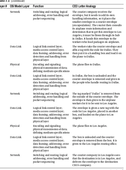
3 Network Switching and routing; logicaladdressing, error handling and packet sequencing
The courier company receives the envelope, but it needs to add its own handling information, so it places the smaller envelope in a courier envelope (encapsulation). The courier then consults its airplane route information and determines that to get this envelope to Los Angeles, it must be flown through its hub in Dallas. It hands this envelope to the workers who load packages on airplanes.
2 Data Link Logical link control layer; media access control layer; data framing; addressing; error detection and handling from physical layer
The workers take the courier envelope and affix a tag with the code for Dallas. They then put it in a handling box and load it on the plane to Dallas.
1 Physical Encoding and signaling; physical transmission of data; defining medium specifications
The plane flies to Dallas.
2 Data Link Logical link control layer; media access control layer; data framing; addressing; error detection and handling from physical layer
In Dallas, the box is unloaded and the courier envelope is removed and given to the people who handle routing in Dallas.
3 Network Switching and routing; logical addressing, error handling and packet sequencing
The tag marked “Dallas” is removed from the outside of the courier envelope. The envelope is then given to the airplane workers for it to be sent to Los Angeles.
2 Data Link Logical link control layer; media access control layer; data framing; addressing; error detection and handling from physical layer
The envelope is given a new tag with the code for Los Angeles, placed in another box, and loaded on the plane to Los Angeles.
1 Physical Encoding and signaling; physical transmission of data; defining medium specifications
The plane flies to Los Angeles.
2 Data Link Logical link control layer; media access control layer; data framing; addressing; error detection and handling from physical layer
The box is unloaded and the courier envelope is removed from the box. It is given to the Los Angeles routing office.
3 Network Switching and routing; logical addressing, error handling and packet sequencing
The courier company in Los Angeles sees that the destination is in Los Angeles, and delivers the envelope to the destination CEO’s company.
Layer #
OSI Model Layer
Function
CEO Letter Analogy
4 Transport Data transfer between endsystems and hosts; connections; segmentation and reassembly; acknowledgments and retransmissions; flow control and error recovery
The mail room removes the inner envelope from the courier envelope and delivers it to the destination CEO’s assistant.
5 Session Establishes, manages, and terminates sessions between applications
The assistant takes the letter out of the envelope.
6 Presentation Data representation and translation, encryption, and compression
The assistant reads the letter and decides whether to give the letter to the CEO, transcribe it to e-mail, or call the CEO.
7 Application Support for application and end-user processes
The CEO receives the message that was sent by his peer in New York.
Table 1-2. (continued)
Now that we know the function of each layer, we will dive into each layer individually and bring them all together after all seven layers have been discussed.
Physical Layer
The physical layer represents any medium—be it air, copper, glass, vacuum—that is used to transmit data over the given medium. The physical layer protocol must define the requirements and rules for creation, maintenance, and termination of the communications channel. In the context of the OSI model, the physical layer receives frames from the data link layer and converts them into signals; ones and zeros to be transmitted over the chosen medium. Examples of transmission mediums and the technologies used to transmit data over them are electromagnetic waves (a.k.a. wireless) for air, photonic (a.k.a. laser) for glass (a.k.a. fiber), and electrical pulses for metallic conductors, such as copper (a.k.a. Cat6 Ethernet). This layer must also specify the relationship between devices and a physical transmission medium to include layouts of pins, voltages, signal timing, frequency, number of waves, light spectrum, data rates, maximum transmission distances, link activation, and deactivation. For physical layer protocols to be useful for networking, they must be able to add context to the data being sent; this context is inserted with the use of a synchronization flag or preamble to delimit one transmission context from another. In summary, the goals of a physical layer protocol are to specify the following:
• The medium of transmission
• The physical manifestation of energy for transmission (e.g., light) • The channel characteristics (half duplex, full duplex, serial, parallel) • The methods for error recovery
Data Link Layer
The data link layer provides services to the layer above it (the network layer), and provides error handling and flow control. This layer must ensure that messages are transmitted to devices on a local area network (LAN) using physical hardware addresses. It also converts packets sent from the network layer into frames to be sent out to the physical layer to transmit. The data link layer converts packets into frames, adding a header containing the device’s physical hardware source and destination addresses, flow control and checksum data
(CRC). The additional information is added to packets form a layer or capsule around the original message, and when the message is received at the distant end, this capsule is removed before the frame is sent to the network layer for processing at that layer. The data frames created by the data link layer is transmitted to the physical layer and converted into some type of signal (electrical or electromagnetic). Please note that devices at the data link layer do not care about logical addressing, only physical. Routers do not care about the actual location of your end user devices, but the data link layer does. This layer is responsible for the identification of the unique hardware address of each device on the LAN.
The data link layer is separated into two sublayers:
• Media access control (MAC) 802.3: This layer is responsible for how packets are transmitted by devices on the network. Media access is first come/first served, meaning all the bandwidth is shared by everyone. Hardware addressing is defined here, as well as the signal path, through physical topologies, including error notification, correct delivery of frames, and flow control. Every network device, computer, server, IP camera, and phone has a MAC hardware address.
• Logical link control (LLC) 802.2: This layer defines and controls error checking and packet synchronization. LLC must locate network layer protocols and encapsulate the packets. The header of the LLC lets the data link layer know how to process a packet when a frame is received.
As mentioned, the MAC layer is responsible for error notification, but this does not include error correction; this responsibility goes to the LLC. When layer 2 frames are received at the end device, the LLC recalculates the checksum to determine if the newly calculated value matches the value sent with the frame. The end device will transmit an acknowledgement signal to the transmitting end unit if the checksum values match. Else, the transmitting end device will retransmit the frame, since it is likely the frame arrived at its destination with corrupted data, or did not arrive at all.
Examples of data link layer technologies include:
• Fiber Distributed Data Interface (FDDI): A legacy technology, but it may still be used in some networks today.
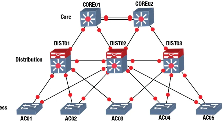
• Asynchronous Transfer Mode (ATM): A legacy technology, but it may still be used in some networks today.
• Institute of Electronic and Electrical Engineers (IEEE) 802.2 (LLC) • IEEE 802.3 (MAC)
• Frame relay: A legacy technology, but it may still be used in some networks today. • PPP (Point-to-Point Protocol)
Network Layer
The network layer provides logical device addressing, determines the location of devices on the network, and calculates the best path to forward packets. Routers are network layer devices that provide routing within networks. This layer provides routing capabilities, creating logical paths or virtual circuits to transmit packets from source to destination. The network layer handles logical packet addressing and maps logical addresses into hardware addresses, allowing packets to reach their endpoint. This layer also chooses the route that packets take, based on factors such as link cost, bandwidth, delay, hop count, priority and traffic.
A network is a collection of many devices, each connected in some manner, which has logical
addressing that allows communication throughout the network, including the devices connected to it. This communication follows the OSI model using the network, data link and physical layers. To understand how packets are processed by network layer devices, let’s look at a simplified example in Figure 1-1. The computer with IP address 192.168.1.1 sends a packet to a router interface; the destination IP address is evaluated by Router 1. Router 1 checks to determine if the destination IP is in one of its local networks. IP address 192.168.2.1 is in the router’s routing table, and is not directly connected to either of its local networks. Router 1 forwards the packet through interface FastEthernet 0/0 (F0/0), as stated in its routing table. Router 2 receives the packet and performs a lookup in its routing table to determine how to route the packet it has received. If the packet is in its routing table, it will forward the packet; else, it will drop the packet. The router sees the IP address in its local routing table and forwards the packet to its destination.
Network layer examples include routing protocols such as Open Shortest Path First (OSPF), Routing Information Protocol (RIP), Enhanced Interior Gateway Protocol (EIGRP), Border Gateway Routing Protocol (BGP), Internet Protocol Version 4/6 (IPv4/IPv6), Internet Group Management Protocol (IGMP), and Internet Control Message Protocol (ICMP).
Transport Layer
The transport layer segments and reassembles data for the session layer. This layer provides end-to-end transport services. The network layer allows this layer to establish a logical connection between source and destination host on a network. The transport layer is responsible for establishing sessions and breaking down virtual circuits. The transport layer connections can be connectionless or connection-oriented, also known as reliable.
192.168.1.1
Router 1 192.168.1.150
Router 2 192.168.2.150
IOU1 IOU2
PC2
192.168.2.1 PC1
Flow control ensures data integrity at the transport layer by using reliable data transport. Reliable data transport uses connection-oriented sessions between end systems. The following are some of the benefits:
• Acknowledgement sent from the receiver to the sender upon receipt of the segments. • If a segment is not acknowledged, it will be retransmitted by the sender.
• Segments are reorganized into their proper order once received at the destination. • Congestion, overloading, and data loss is avoided through flow control.
Connection-Oriented
In reliable transport, when a device wants to transmit, it must set up connection-oriented communication by creating a session with a remote device. The session is set up by completing a three-way handshake. Once the three-way handshake is complete, the session resembles a virtual-circuit for the communication. A connection-oriented session implies that the method of communication is bidirectional, and the receiving party is expected to acknowledge the data received. The connection-oriented session analogy is akin to having a conversation (not a monologue) with someone. After the transfer is complete, the session is terminated and the virtual circuit is torn down. During the establishment of the reliable session, both hosts must negotiate and agree to certain parameters to begin transferring data. Once the connection is synchronized and established, traffic can be processed. Connection-oriented communication is needed when trying to send files via file transfer, as a connection must be made before the files can be sent. Connectionless communication is used for applications that require fast performance, such as video chatting.
Session Layer
The session layer is responsible for establishing, managing, and terminating sessions between local and remote applications. This layer controls connections between end devices and offers three modes of communication: full-duplex, half-duplex, or simplex operation. The session layer keeps applications data away from other applications data. This layer performs reassembly of data in connection-oriented mode while data is passed through, without being modified when using connectionless mode. The session layer is also responsible for the graceful close of sessions, creating checkpoints and recovery when data or connections are interrupted. This layer has the ability to resume connections or file transfers where it stopped last.
Examples of the session layer include:
• Structure Query Language (SQL): An IBM development designed to provide users with a way to define information requirements on local and remote systems.
• Remote Procedure Call (RPC): A client-server redirection tool used to disparate service environments.
Presentation Layer
The presentation layer translates data, formats code, and represents it to the application layer. This layer identifies the syntax that different applications use, and encapsulates presentation data into session protocol data units and passes this to the session layer, ensuring that data transferred from the local application layer can be read by the application layer at the remote system. The presentation layer translates data into the form that specific applications recognize and accept. If a program uses a non-ASCII code page, this layer will translate the received data into ASCII. This layer also encrypts data to be sent across the network. The presentation layer also can compress data, which increases the speed of the network. If the data is encrypted, it can only be decrypted at the application layer on the receiving system.
Examples of presentation layer standards include:
• Joint Photographic Experts Group (JPEG): Photo standards.
• Movie Picture Experts Group (MPEG) standard for compression and coding of motion video for CDs.
• Tagged Image File Format (TIFF): A high-resolution graphics format.
• Rich Text Format (RTF): A file format for exchanging text files from different word processors and operating systems.
Application Layer
The application layer interfaces between the program sending or receiving data. This layer supports end user applications. Application services are made for electronic mail (e-mail), Telnet, File Transfer Protocol (FTP) applications, and file transfers. Quality of service, user authentication, and privacy are considered at this layer due to everything being application-specific. When you send an e-mail, your e-mail program contacts the application layer.
The following are popular applications within the application layer:
• World Wide Web (WWW): Presents diverse formats—including multimedia such as graphics, text, sound, and video connecting servers—to end users.
• E-mail: Simple Mail Transfer Protocol (SMTP) and Post Office Protocol version 3 (POP3) protocols are used to allow sending and receiving, respectively, of e-mail messages between different e-mail applications.
The OSI Model: Bringing It All Together
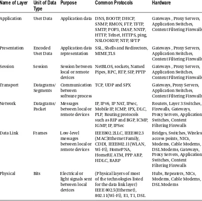
Table 1-3. The Functions of Each Layer in the OSI Model
Name of Layer
Unit of Data
Type
Purpose
Common Protocols
Hardware
Application User Data Application data DNS, BOOTP, DHCP, SNMP, RMON, FTP, TFTP, SMTP, POP3, IMAP, NNTP, HTTP, Telnet, HTTPS, ping, NSLOOKUP, NTP, SFTP
Gateways , Proxy Servers, Application Switches,
SSL, Shells and Redirectors, MIME,TLS
Gateways , Proxy Servers, Application Switches, Content Filtering Firewalls
Session Session Session between local or remote devices
NetBLOS, sockets, Named Pipes, RPC, RTP, SIP, PPTP
Gateways , Proxy Servers, Application Switches,
TCP, UDP and SPX Gateways, Proxy Servers, Application Switches, Mobile IP, ICMP, IPX, DLC, PLP, Routing protocols such as RIP and BGP, ICMP, IGMP, IP, IPSec
Routers, Layer 3 Switches, Firewalls, Gateways, Proxy Servers, Application Switches, Content Filtering Firewalls
Data Link Frames Low-level messages HomeRF, ATM, PPP ARP, HDLC, RARP
Physical Bits Electrical or light signals sent between local devices
(Physical layers of most of the technologies listed for the data link layer)
Let’s bring the OSI model together in a way where you can see the importance of each layer. How about using Firefox to browse to a web site on a computer? You type apress.com into the web browser to contact the web server hosting the content you are requesting. This is at the application layer.
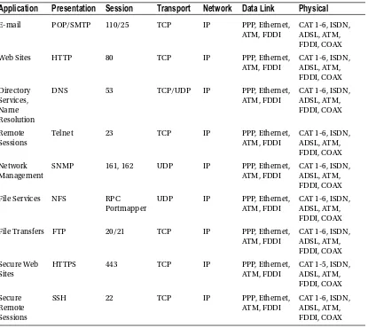
Table 1-4 shows many examples of applications and how each layer supports another.
TCP/IP Protocol
TCP/IP is the most used network protocol. Since you now have a firm grasp of the OSI model, we will display the correlation between the TCP/IP and OSI models. As discussed, the OSI model has seven layers, and the TCP/IP protocol has four layers. Table 1-5 shows the comparison between the OSI and TCP/IP protocol. Table 1-4. Examples of Applications and How Each Layer Helps the Applications Come Together
Application
Presentation
Session
Transport
Network
Data Link
Physical
E-mail POP/SMTP 110/25 TCP IP PPP, Ethernet,
ATM, FDDI
CAT 1-6, ISDN, ADSL, ATM, FDDI, COAX
Web Sites HTTP 80 TCP IP PPP, Ethernet,
ATM, FDDI
DNS 53 TCP/UDP IP PPP, Ethernet,
ATM, FDDI
Telnet 23 TCP IP PPP, Ethernet,
ATM, FDDI
SNMP 161, 162 UDP IP PPP, Ethernet,
ATM, FDDI
CAT 1-6, ISDN, ADSL, ATM, FDDI, COAX
File Services NFS RPC
Portmapper
UDP IP PPP, Ethernet,
ATM, FDDI
CAT 1-6, ISDN, ADSL, ATM, FDDI, COAX
File Transfers FTP 20/21 TCP IP PPP, Ethernet,
ATM, FDDI
HTTPS 443 TCP IP PPP, Ethernet,
ATM, FDDI
SSH 22 TCP IP PPP, Ethernet,
ATM, FDDI
The application, presentation, and session layers in the OSI model correspond to the application layer in the TCP/IP model. The transport layer in the OSI model correlates to the transport layer in the TCP/IP model. The network layer in the OSI model correlates to the Internet layer in the TCP/IP model. The data link and physical layers correspond with the network interface layer in the TCP/IP model.
Similarly, when a sender transmits data via the TCP/IP protocol, applications communicate with the application layer, which sends its data to the transport layer, which sends its data to the Internet layer, which sends its data to the network interface layer to send the data over the transmission medium to the destination.
Now we will dive into the layers of the TCP/IP model.
TCP/IP Application Layer
Programs communicate to the TCP/IP application layer. Many protocols can be used at this layer, depending on the program being used. This layer also defines user interface specifications.
Several protocols are used at this layer, most notably File Transfer Protocol (FTP) for file transfers,
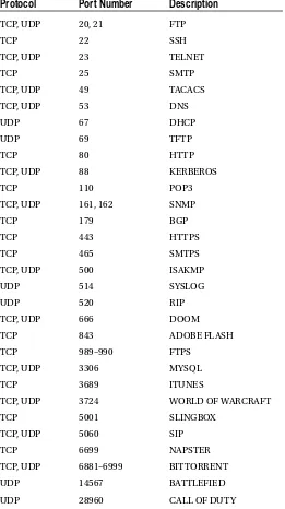
Simple Mail Transport Protocol (SMTP) for e-mail data, and HyperText Transfer Protocol (HTTP) for web site traffic. This layer communicates with the transport layer via ports. The Internet Assigned Numbers Authority (IANA) defines which ports are to be used for which application. Standard applications always listen on port 80 for the HTTP protocol, the SMTP protocol uses port 25, and the FTP protocol uses ports 20 and 21 for sending data. The port number tells the transport protocol what type of data is inside the packet (for example, what data is being transported from a web server to a host), allowing the application protocol at the receiving side to use port 80, which will deliver the data to the web browser that requested the data.
TCP/IP Transport Layer
The TCP/IPtransport layer is identical to and parallels performing the same functions as the transport layer in the OSI model. Two protocols can be used at this layer: Transmission Control Protocol (TCP) and User Datagram Protocol (UDP). The first is connection-oriented and the latter is connectionless, meaning that the TCP provides reliability and error-free delivery of data, and also maintains data integrity. TCP is used for e-mails and web site data, whereas UDP is usually used to send control data, including voice and other Table 1-5. OSI Model Comparison to TCP/IP Model with Functions of Each Layer
OSI Model
TCP/IP Model
Function
Application Application The application layer defines TCP/IP application protocols and how programs interface with transport layer services using the network.
Presentation
Session
Transport Transport (Host-to-Host) The transport layer handles communication session
management between end systems. It also defines the level of service and the status of connections.
Network Internetwork The Internet layer encapsulates data into IP datagrams, containing source and destination addresses used to route datagrams between end systems
Data Link Network Interface The network layer defines how data is actually sent through the network, including hardware devices and network mediums such as cables
The transport layer receives data from the application layer and breaks it up into many packets of data. As mentioned earlier, the transport layer uses two protocols: TCP and UDP. The TCP protocol receives packets from the Internet layer, reorders the packets correctly (since packets may arrive out of order), evaluates the data in the packet, and sends an acknowledgement signal to the sender. The sender will resend the packet if no acknowledgement signal is received. Packets need to be resent if the original packet was corrupted or did not arrive at the destination. For this reason, TCP is called a reliable protocol; whereas UDP is unreliable because it does not reorder packets or send an acknowledgement signal to the sender. When UDP is used, it is the responsibility of the application to reorder packets. Both UDP and TCP receive data from the application layer and add a header to the data before sending to the Internet layer. After receiving packets from the Internet layer, the header is removed in order to forward data to the application layer and the correct port. The header contains the following information: a checksum to check whether data is intact and not corrupt; a source and destination port number; and a sequence number for reordering packets and acknowledgement. Figure 1-2 shows packets at the transport layer with header added to it.
TCP/UDP
Header
Data
Data
Application Layer
Transport Layer
Figure 1-2. Transport layer packet
TCP/IP Internet Layer
The TCP/IP Internet layer correlates to the network layer in the OSI model and is responsible for routing and addressing. The most common protocol used at this layer is the Internet Protocol (IP). This layer logically addresses packets with IP addresses and routes packets to different networks.
The Internet layer receives packets from the transport layer, adds source and destination IP addresses to the packet, and forwards this on to the network interface layer for transmitting to the sender. The logical (virtual addressing), also known as an IP address, allows the packet to be routed to its destination. Along the way, packets traverse many locations through routers before reaching its destination. To view an example of this, open your command prompt on your laptop or workstation. In the command prompt, enter tracert (or traceroute in Linux) apress.com. You will see the number of routers that the packet traverses to its destination.
There are many protocols in use at the Internet layer, including:
• Address Resolution Protocol (ARP): ARP is used to map IP network addresses to the hardware address that uses the data link protocol. This will be discussed further in Chapter 3.
• Reverse Address Resolution Protocol (RARP): RARP is used on workstations in a LAN to request its IP address from the ARP table.
The maximum size of the frames that are sent over a network is called the maximum transfer unit (MTU). Ethernet networks, by default, support up to 1,500 bytes, so the MTU is 1,500 bytes. The IP protocol also has a field in its header to support fragmentation. Fragmentation provides a method for networks or routers that do not support 1,500 bytes the ability to break the datagram into chunks in order to reach its destination. Once the router at the destination receives the datagram, it will reorder the fragmented frames before delivery. Figure 1-3 shows the addition of the IP header after a packet is received from the transport layer.
TCP/IP Network Interface Layer
The TCP/IP network interface layer relates to the data link and physical layers of the OSI model. It is responsible for using physical hardware addresses to transmit data, and defines protocols for the physical transmission of data.
Datagrams are transmitted to the network interface layer to be forwarded to its destination. This layer is defined by the type of physical connection your computer has. Most likely it will be Ethernet or wireless.
The logical link control (LLC) layer is responsible for adding the protocol used to transmit data at the Internet layer. This is necessary so the corresponding network interface layer on the receiving end knows which protocol to deliver the data to at the Internet layer. IEEE 802.2 protocol defines this layer.
Media access control (MAC) is responsible for assembling the frame that is sent over the network. It also adds the source and destination MAC addresses. This layer is defined by the IEEE 802.3 and 802.11 protocols. As shown in Figure 1-4, the LLC and MAC layers add their own headers to the datagram. The transport layer operates on datagrams or segments. When packets are received by the Internet layer, they are decapsulated into datagrams; when packets are received by the network interface layer, they are converted into Ethernet frames before being forwarded to their destination.
Application Layer
Transport Layer
Internet Layer
Header
IP
TCP/UDP
Header
Data
TCP/UDP
Header
Data
Data
Reliability
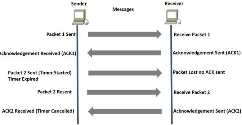
How can TCP provide reliability? Through the use of acknowledgements, of course. TCP uses sequence numbers to identify the correct order of segments sent from each end device so that data can be reconstructed at the receiving end, regardless of fragmentation or packet loss. For every packet that is transmitted, the sequence number is incremented by one. The starting sequence number is randomly generated to defend against sequence prediction attacks. TCP also uses sequence numbers for error detection, allowing senders to retransmit packets that are corrupt or lost. Checksums are performed to ensure the IP header information has not been corrupted. TCP flags located in the header of TCP packets are used to control the state of a connection. Before we go through a TCP example let’s define the three TCP flags we will cover:
• Synchronize (SYN): Used to initiate and setup a session and agree on initial sequence numbers.
• Finish (FIN): Used to gracefully terminate a session. This shows that the sender has no more data to transmit.
• Acknowledgement (ACK): Used to acknowldegemt receipt of data.
Figure 1-5 displays how TCP provides reliability. The sender has sent a packet and the receiver acknowledges this packet by increasing the sequence number by one. The sender sends packet 2 and starts a timer. The packet is lost, no acknowledgement is sent back, and the timer expires. The sender resends the packet and the receiver acknowledges with an ACK.
MAC
Three-Way Handshake and Connection Termination
When establishing a connection, TCP uses a three-way handshake. The process starts with a SYN sent by a client to a server. The server responds back with a SYN-ACK, with the acknowledgement being increased by one. Finally, the client sends an ACK back to the server to complete the connection setup.
To end a connection, a four-way handshake is completed to terminate the connection. The end that wishes to end the connection transmits a FIN packet, and the other end acknowledges with an ACK. The receiving end now sends a FIN packet with ACK. Finally, the initiating end sends an ACK to terminate the connection. Figure 1-6 shows the three- and four-way handshake processes.