Code of Standard Practice
for Steel Buildings
and Bridges
June 15, 2016
Supersedes the Code of Standard Practice for Steel Buildings and Bridges
dated April 14, 2010 and all previous versions
Approved by the Committee on the Code of Standard Practice
AMERICAN INSTITUTE OF STEEL CONSTRUCTION
16.3-ii
© AISC 2016
by
American Institute of Steel Construction
All rights reserved. This book or any part thereof must not be reproduced in any form without the
written permission of the publisher. The AISC logo is a registered trademark of AISC.
The information presented in this publication has been prepared by a balanced committee following American National Standards Institute (ANSI) consensus procedures and recog-nized principles of design, construction and contract interpretation. This document is intended as a statement of custom and usage in structural steel construction. Competent design, construction and legal advice should be sought when applying the provisions of this document to a specific construction project or contract document. The publication of this information is not a representation or warranty on the part of the American Institute of Steel Construction, its officers, agents, employees or committee members, or of any other person named herein. All representations or warranties, express or implied, other than as stated above, are specifically disclaimed. Anyone making use of the information presented in this publication assumes all liability arising from such use.
Caution must be exercised when relying upon standards and guidelines developed by other bodies and incorporated by reference herein, since such material may be modified or amended from time to time subsequent to the publication of this edition. The American Institute of Steel Construction bears no responsibility for such material other than to refer to it and incorporate it by reference at the time of the initial publication of this edition.
Printed in the United States of America
PREFACE
(This Preface is not part of ANSI/AISC 303-16, but is included for informational purposes only.)
As in any industry, trade practices have developed among those that are involved in the design, purchase, fabrication and erection of structural steel. This Code provides a useful framework for a common understanding of the acceptable standards when contracting for structural steel. As such, it is useful for owners, architects, engineers, general contractors, construction managers, fabricators, steel detailers, erectors and others associated with con-struction in structural steel. Unless specific provisions to the contrary are contained in the contract documents, the existing trade practices contained herein are considered to be the standard custom and usage of the industry and are thereby incorporated into the relation-ships between the parties to a contract.
It is important to note the differences in design requirements between buildings and bridges. ANSI/AISC 360 and 341 establish the design requirements for buildings and building-like structures, and this Code sets complementary commercial and technical requirements. For highway bridges, the governing design requirements are established by AASHTO and implemented by the contracting agency; the commercial provisions of the Code are appli-cable, but technical provisions, such as tolerances, are not addressed.
The Symbols and Glossary are an integral part of this Code. In many sections of this Code, a nonmandatory Commentary has been prepared to provide background and further explanation for the corresponding Code provisions. The user is encouraged to consult it.
This Code is written—and intended to be utilized in practice—as a unified document. Contract documents may supercede individual provisions of the Code as provided in Section 1.1, except when doing so would violate a requirement of the applicable building code.
Since the first edition of this Code was published in 1924, AISC has continuously sur-veyed the structural steel design community and construction industry to determine standard trade practices. Since then, this Code has been periodically updated to reflect new and changing technology and industry practices.
The 2000 edition was the fifth complete revision of this Code since it was first published. Like the 2005 and 2010 editions, the 2016 edition is not a complete revision but does add important changes and updates. It is the result of the deliberations of a fair and balanced Committee, the membership of which included structural engineers, architects, a code offi-cial, a general contractor, fabricators, a steel detailer, erectors, inspectors and an attorney. The following changes have been made in this revision:
• This Code is formally accredited by ANSI as an American National Standard.
• The language throughout the entire Code has been generalized to address contracts that utilize drawings, models, or drawings and models in combination, and Appendix A, which previously addressed models separately, has been eliminated.
• The Commentary in Section 1.1 has been updated to acknowledge that some portions of ANSI/AISC 303 are incorporated into the International Building Codethrough reference to those provisions in ANSI/AISC 360 and 341.
• The list of dates of referenced documents in Section 1.2 has been editorially updated. • A new Section 1.4 has been added to address responsibility for identifying contract docu
16.3-iv PREFACE
• Section 1.10 has increased emphasis that the absence of a tolerance in this Code does not mean that tolerance is zero.
• Section 1.11 has been added to address marking requirements for protected zones in frames designed to meet the requirements of ANSI/AISC 341.
• A reference has been added in the Commentary to Section 2.2 to AISC Design Guide 27 for stainless steel.
• In Section 3.1, two items are added to the list of required information: preset requirements for free ends of cantilevered members and the drawing information required in ANSI/AISC 341.
• Sections 3.1.1 and 3.1.2 have been editorially switched in order. The resulting Section 3.1.2 (formerly Section 3.1.1) also has been improved to better address what is required for bidding when the owner’s designated representative for design delegates the determi-nation and design of member reinforcement at connections to the licensed engineer in responsible charge of the connection design.
• Section 3.2 has been updated to address revisions, if they are necessary, when referenced contract documents are not available at the time of design, bidding, detailing or fabrication. • Section 3.3 has added emphasis that the fabricator need not discover design discrepancies. • Sections 3.7 and 4.2.2 have been added to address intellectual property rights of the
owner’s designated representative for design and the fabricator, respectively.
• Section 4.4 has been clarified to better reflect the role of the connection design criteria required in Section 3.1.1 when connection design work is delegated.
• Commentary has been added to Section 4.5 to address potential pitfalls when fabrication and erection documents are not furnished by the fabricator.
• In Section 6.1.1, the listed shop-standard material grades have changed for HP-shapes and HSS.
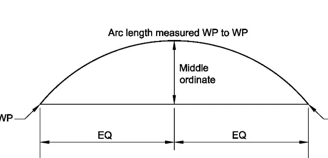
• In Section 6.4.2, the tolerance for curved members has been improved.
• In Section 7.5.1, tolerances for anchor-rod placement have been revised for consistency with the hole sizes provided the AISC Steel Construction Manualand the tolerances given in ACI 117.
• In Section 7.8.3, the number of extra bolts required to be supplied has been increased to account for bolt loss and pre-installation verification testing requirements; also, backing has been clarified as steel backing.
• In Section 7.8.4, non-steel backing is now addressed.
• In Section 7.13, the term “building line” has been changed to “building exterior.” • Commentary has been added in Section 7.13.1.2(e) to coordinate with the cantilevered
member preset information added in Section 3.1.
• Section 9.1.5 has been added to address allowances, when used.
• Section 10 has been significantly revised with multiple categories for AESS and different treatments required for each.
The Committee thanks Jeffrey Dave, Douglas Fitzpatrick, Angela Stephens and Lawrence Kruth for their contributions to integrating treatment of model-based contracts throughout this Code; Walter Koppelaar, Terri Boake and Jack Petersen for their contributions to the update of Section 10; and, George Wendt, Charles Wood, John Rogers and Brian Smith for their contributions to the improvement of tolerances for curved members.
The Committee thanks Michael J. Tylk, Donald G. Moore and Paul M. Brosnahan for their contributions as members of the Committee for part of this cycle, and honors Committee member Keith G. Landwehr, who passed away during this cycle.
By the AISC Committee on the Code of Standard Practice,
Babette C. Freund, Chair Viji Kuruvilla William A. Andrews, Vice Chair James L. Larson
Jon D. Andrews H. Scott Metzger
Scott F. Armbrust James A. Minkkinen
Barry L. Barger, Emeritus David B. Ratterman
William R. Davidson David I. Ruby
Theodore L. Droessler James A. Stori
Donald T. Engler Thomas S. Tarpy, Jr.
Lawrence G. Griffis James G. Thompson
Samuel G. Haldiman Steven F. Weiss
Timothy J. Hanenburg Michael A. West
D. Kirk Harman Charles J. Carter, Secretary
TABLE OF CONTENTS
GLOSSARY . . . ix
SECTION 1. GENERAL PROVISIONS . . . 1
1.1. Scope . . . 1
1.2. Dates of Referenced Specifications, Codes and Standards . . . 1
1.3. Units . . . 3
1.4. Responsibility for Identifying Contract Documents . . . .3
1.5. Design Criteria . . . 3
1.6. Responsibility for Design . . . 4
1.7. Patents and Copyrights . . . 4
1.8. Existing Structures . . . 4
1.9. Means, Methods and Safety of Erection . . . 4
1.10. Tolerances . . . 5
1.11. Marking of Protected Zones in High-Seismic Applications . . . 5
SECTION 2. CLASSIFICATION OF MATERIALS . . . 6
2.1. Definition of Structural Steel . . . 6
2.2. Other Steel, Iron or Metal Items . . . 7
SECTION 3. DESIGN DOCUMENTS AND SPECIFICATIONS . . . 9
3.1. Structural Design Documents and Specifications . . . 9
3.2. Architectural, Electrical and Mechanical Design Documents and Specifications . . . 16
3.3. Discrepancies . . . 16
3.4. Legibility of the Design Drawings . . . 16
3.5. Revisions to the Design Documents and Specifications . . . 17
3.6. Fast-Track Project Delivery . . . 18
3.7. Intellectual Property . . . 18
SECTION 4. APPROVAL DOCUMENTS . . . 19
4.1. Owner Responsibility . . . 19
4.2. Fabricator Responsibility . . . 20
4.3. Use of Digital Files or Copies of the Design Documents . . . 21
4.4. Approval . . . .23
4.5. Fabrication and/or Erection Documents Not Furnished by the Fabricator . . . 25
4.6. The RFI Process . . . 25
4.7. Erection Documents . . . 26
SECTION 5. MATERIALS . . . 27
5.1. Mill Materials . . . 27
SECTION 6. SHOP FABRICATION AND DELIVERY . . . 30
6.1. Identification of Material . . . 30
6.2. Preparation of Material . . . 31
6.3. Fitting and Fastening . . . 31
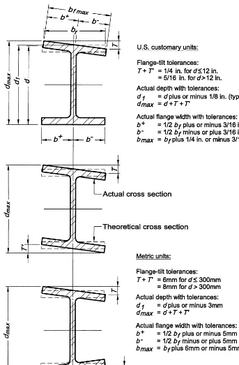
6.4. Fabrication Tolerances . . . 32
6.5. Shop Cleaning and Painting . . . 35
6.6. Marking and Shipping of Materials . . . 37
6.7. Delivery of Materials . . . 38
SECTION 7. ERECTION . . . 39
7.1. Method of Erection . . . 39
7.2. Job-Site Conditions . . . 39
7.3. Foundations, Piers and Abutments . . . 39
7.4. Lines and Benchmarks . . . 40
7.5. Installation of Anchor Rods, Foundation Bolts, and Other Embedded Items . . . . 40
7.6. Installation of Bearing Devices . . . 41
7.7. Grouting . . . 41
7.8. Field Connection Material . . . 42
7.9. Loose Material . . . 43
7.10. Temporary Support of Structural Steel Frames . . . 43
7.11. Safety Protection . . . 46
7.12. Structural Steel Frame Tolerances . . . 46
7.13. Erection Tolerances . . . 47
7.14. Correction of Errors . . . 57
7.15. Cuts, Alterations and Holes for Other Trades . . . 57
7.16. Handling and Storage . . . 58
7.17. Field Painting . . . 58
7.18. Final Cleaning Up . . . 58
SECTION 8. QUALITY CONTROL . . . 59
8.1. General . . . 59
8.2. Inspection of Mill Material . . . 59
8.3. Nondestructive Testing . . . 60
8.4. Surface Preparation and Shop Painting Inspection . . . 60
8.5. Independent Inspection . . . 60
SECTION 9. CONTRACTS . . . 61
9.1. Types of Contracts . . . 61
9.2. Calculation of Weights . . . 61
9.3. Revisions to the Contract Documents . . . 63
9.4. Contract Price Adjustment . . . 63
9.5. Scheduling . . . 63
16.3-viii TABLE OF CONTENTS
SECTION 10. ARCHITECTURALLY EXPOSED STRUCTURAL STEEL . . . 65
10.1. General Requirements . . . 65
10.2. Contract Documents . . . 66
10.3. Approval Documents . . . 66
10.4. Fabrication . . . . 68
10.5. Delivery of Materials . . . 69
GLOSSARY
The following abbreviations and terms are used in this Code. Where used, terms are itali-cized to alert the user that the term is defined in this Glossary.
AASHTO. American Association of State Highway and Transportation Officials.
Adjustable items. See Section 7.13.1.3.
AESS. See architecturally exposed structural steel.
AISC. American Institute of Steel Construction.
Allowance. A monetary amount included in a contract as a placeholder for work that is antici -pated but not defined at the time the contract is executed.
Anchor bolt. See anchor rod.
Anchor rod. A mechanical device that is either cast or drilled and chemically adhered, grouted or wedged into concrete and/or masonry for the purpose of the subsequent attach-ment of structural steel.
ANSI. American National Standards Institute.
Approval documents. The structural steel shop drawings, erection drawings, and embedment drawings, or where the parties have agreed in the contract documentsto provide digital model(s), the fabricationand erection models. A combination of drawings and digital models also may be provided.
Architect. The entity that is professionally qualified and duly licensed to perform architec-tural services.
Architecturally exposed structural steel. See Section 10.
AREMA. American Railway Engineering and Maintenance of Way Association.
ASME. American Society of Mechanical Engineers.
ASTM. American Society for Testing and Materials.
AWS. American Welding Society.
Bearing devices. Shop-attached base and bearing plates, loose base and bearing plates, and leveling devices, such as leveling plates, leveling nuts and washers, and leveling screws.
16.3-x GLOSSARY
Clarification. An interpretation, of the design drawings or specifications that have been released for construction, made in response to an RFIor a note on an approval drawing and providing an explanation that neither revises the information that has been released for construction nor alters the cost or schedule of performance of the work.
The Code, This Code. This document, the AISC Code of Standard Practice for Steel Buildings and Bridgesas adopted by the American Institute of Steel Construction.
Column line. The grid line of column centers set in the field based on the dimensions shown on the structural design documentsand using the building layout provided by the owner’s designated representative for construction. Column offsets are taken from the column line. The column linemay be straight or curved as shown in the structural design documents.
Connection. An assembly of one or more joints that is used to transmit forces between two or more members and/or connectionelements.
Contract documents. The documents that define the responsibilities of the parties that are involved in bidding, fabricating and erecting structural steel. These documents normally include the design documents, the specificationsand the contract.
Design documents. The design drawings, or where the parties have agreed in the contract documentsto provide digital model(s), the design model. A combination of drawings and digital models also may be provided.
Design drawings. The graphic and pictorial portions of the contract documentsshowing the design, location and dimensions of the work. These documents generally include, but are not necessarily limited to, plans, elevations, sections, details, schedules, diagrams and notes.
Design model. A dimensionally accurate 3D digital model of the structure that conveys the structural steelrequirements given in Section 3.1 for the building.
Detailer. See steel detailer.
Embedment drawings. Drawings that show the location and placement of items that are installed to receive structural steel.
EOR, engineer, engineer of record. See structural engineer of record.
Erection bracing drawings. Drawings that are prepared by the erector to illustrate the sequence of erection, any requirements for temporary supports and the requirements for raising, bolting and/or welding. These drawings are in addition to the erection drawings.
Erection documents. Theerection drawings, or where the parties have agreed in the contract documentsto provide digital model(s), the erection model. A combination of drawings and digital models also may be provided.
Erection model. A dimensionally accurate 3D digital model produced to convey the infor-mation necessary to erect the structural steel. This may be the same digital model as the fabrication model, but it is not required to be.
Erector. The entity that is responsible for the erection of the structural steel.
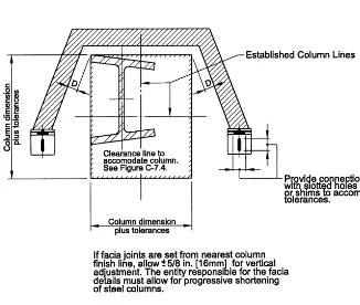
Established column line. The actual field line that is most representative of the erected column centers along a line of columns placed using the dimensions shown in the struc-tural design drawingsor design modeland the lines and benchmarks established by the owner’s designated representative for construction, to be used in applying the erection tolerances given in this Code for column shipping pieces.
Fabrication documents. The shop drawings, or where the parties have agreed in the contract documentsto provide digital model(s), the fabrication model. A combination of drawings and digital models also may be provided.
Fabrication model. A dimensionally accurate 3D digital model produced to convey the information necessary to fabricate the structural steel. This may be the same digital model as the erection model, but it is not required to be.
Fabricator. The entity that is responsible for detailing (except in Section 4.5) and fabricating the structural steel.
Hazardous materials. Components, compounds or devices that are either encountered during the performance of the contract work or incorporated into it containing substances that, not withstanding the application of reasonable care, present a threat of harm to per-sons and/or the environment.
Inspector. The owner’stesting and inspection agency.
Levels of development, LOD. The levels of completeness of the digital model(s) or digital model elements.
MBMA. Metal Building Manufacturers Association.
Mill material. Steel mill products that are ordered expressly for the requirements of a specific project.
Owner. The entity that is identified as such in the contract documents.
Owner’s designated representative for construction. The owneror the entity that is respon-sible to the ownerfor the overall construction of the project, including its planning, quality, and completion. This is usually the general contractor, the construction manager or similar authority at the job site.
Owner’s designated representative for design. The owneror the entity that is responsible to the ownerfor the overall structural design of the project, including the structural steel frame. This is usually the structural engineer of record.
16.3-xii GLOSSARY
RCSC. Research Council on Structural Connections.
Released for construction. The term that describes the status of contract documents that are in such a condition that the fabricatorand the erectorcan rely upon them for the per-formance of their work, including the ordering of material and the preparation of shop and erection drawingsor fabricationand erection models.
Revision. An instruction or directive providing information that differs from information that has been released for construction. A revisionmay, but does not always, impact the cost or schedule of performance of the work.
RFI. A written request for information or clarificationgenerated during the construction phase of the project.
SER. Seestructural engineer of record.
Shop drawings. Drawings of the individual structural steel shipping pieces that are to be produced in the fabrication shop.
SJI. Steel Joist Institute.
Specifications. The portion of the contract documentsthat consists of the written require-ments for materials, standards and workmanship.
SSPC. SSPC: The Society for Protective Coatings, which was formerly known as the Steel Structures Painting Council.
Standard structural shapes. Hot-rolled W-, S-, M- and HP-shapes, channels and angles listed in ASTM A6/A6M; structural tees split from the hot-rolled W-, S- and M- shapes listed in ASTM A6/A6M; hollow structural sections produced to ASTM A500/A500M, A501/A501M, A618/A618M, A847/A847M, A1065/A1065M, or A1085/A1085M; and, steel pipe produced to ASTM A53/A53M.
Steel detailer. The entity that produces theapproval documents.
Structural engineer of record. The licensed professional who is responsible for sealing the contract documents, which indicates that he or she has performed or supervised the analy-sis, design and document preparation for the structure and has knowledge of the load-carrying structural system.
Structural steel. The elements of the structural frame as given in Section 2.1.
Substantiating connection information. Information submitted by the fabricator, if requested by the owner’s designated representative for designin the contract documents, when Option 2 or Option 3 is designated for connectionsper Section 3.1.1.
Tier. The structural steel framing defined by a column shipping piece.
CODE OF STANDARD PRACTICE
FOR STEEL BUILDINGS AND BRIDGES
SECTION 1. GENERAL PROVISIONS
1.1. Scope
This Code sets forth criteria for the trade practices involved in steel buildings, bridges and other structures, where other structures are defined as those structures designed, fabricated and erected in a manner similar to buildings, with building-like vertical and lateral force-resisting elements. In the absence of specific instructions to the contrary in the contract documents, the trade practices that are defined in this Code shall govern the fabrication and erection of structural steel.
Commentary:
The practices defined in this Code are the commonly accepted standards of custom and usage for structural steelfabrication and erection, which generally represent the most efficient approach. Some provisions in this Code have been incorporated by reference into the International Building Code; see www.aisc.org/303IBC.
This Code is not intended to define a professional standard of care for the owner’s designated representative for design; change the duties and responsibilities of the owner, contractor, architector structural engineer of recordfrom those set forth in the contract documents; nor assign to the owner, architector structural engineer of recordany duty or authority to undertake responsibility incon sistent with the provi-sions of the contract documents.
This Code is not applicable to steel joists or metal building systems, which are addressed by SJI and MBMA, respectively.
1.2. Dates of Referenced Specifications, Codes and Standards
The following dated versions of documents are referenced in this Code:
AASHTO Specification—2014 AASHTO LRFD Bridge Design Specifications, 7th Edition, with 2015 and 2016 Interim Revisions.
ANSI/AISC 341—ANSI/AISC 341-16, AISC Seismic Provisions for Structural Steel Buildings.
ANSI/AISC 360—ANSI/AISC 360-16, AISC Specification for Structural Steel Buildings.
ASME B46.1—ASME B46.1-09, Surface Texture (Surface Roughness, Waviness, and Lay).
16.3-2 GENERAL PROVISIONS
ASTM A6/A6M-14, Standard Specification for General Requirements for Rolled Structural Steel Bars, Plates, Shapes, and Sheet Piling.
ASTM A36/A36M-14, Standard Specification for Carbon Structural Steel.
ASTM A53/A53M-12, Standard Specification for Pipe, Steel, Black and Hot-Dipped, Zinc-Coated, Welded and Seamless.
ASTM A500/A500M-13, Standard Specification for Cold-Formed Welded and Seamless Carbon Steel Structural Tubing in Rounds and Shapes.
ASTM A501/A501M-14, Standard Specification for Hot-Formed Welded and Seamless Carbon Steel Structural Tubing.
ASTM A572/A572M-15, Standard Specification for High-Strength Low-Alloy Columbium-Vanadium Structural Steel.
ASTM A618/A618M-04(2015), Standard Specification for Hot-Formed Welded and Seamless High-Strength Low-Alloy Structural Tubing.
ASTM A847/A847M-14, Standard Specification for Cold-Formed Welded and Seamless High-Strength, Low-Alloy Structural Tubing with Improved Atmospheric Corrosion Resistance.
ASTM A992/A992M-11(2015), Standard Specification for Structural Steel Shapes. ASTM A1065/A1065/M-15, Standard Specification for Cold-Formed
Electric-Fusion (Arc) Welded High-Strength Low-Alloy Structural Tubing in Shapes, with 50 ksi [345 MPa] Minimum Yield Point.
ASTM A1085/A1085M-15, Standard Specification for Cold-Formed Welded Carbon Steel Hollow Structural Sections (HSS).
AWS D1.1/D1.1M—AWS D1.1/D1.1M:2015 Structural Welding Code—Steel. RCSC Specification—Specification for Structural Joints Using High-Strength Bolts,
2014.
SSPC SP1—SSPC Surface Preparation Specification No. 1, Solvent Cleaning, 2015. SSPC SP2—SSPC Surface Preparation Specification No. 2, Hand Tool Cleaning,
2004.
SSPC SP6—SSPC Surface Preparation Specification No. 6, Commercial Blast Cleaning, 2007.
Commentary:
Additionally, the following dated versions of documents are referenced in the Commentary on this Code:
AIA Document E202—2008 Building Information Modeling Protocol Exhibit AIA Document E203—2013 Building Information Modeling and Digital Data
Exhibit
AIA Document G201—2013 Project Digital Data Protocol Form
AIA Document G202—2013 Project Building Information Modeling Protocol Form
ASTM A563-15, Standard Specification for Carbon and Alloy Steel Nuts. ASTM A563M-07(2013), Standard Specification for Carbon and Alloy Steel Nuts
(Metric).
BIMFORUM 2013 Level of Development Specification.
CASE Document 962—National Practice Guidelines for the Structural Engineer of Record, 2012.
Consensus Docs 301—2013 BIM Addendum.
1.3. Units
In this Code, the values stated in either U.S. customary units or metric units shall be used. Each system shall be used independently of the other.
Commentary:
In this Code, dimensions, weights and other measures are given in U.S. customary units with rounded or rationalized metric-unit equivalents in brackets. Be cause the values stated in each system are not exact equivalents, the selective combination of values from each of the two systems is not permitted.
1.4 Responsibility for Identifying Contract Documents
The owner’s designated representative for construction shall identify all contract documents. When the design drawingsand a design modelare both provided, the owner’s designated representative for design shall specify which document is the controlling contract document. The contract documents shall establish the proce-dures for communicating changes to the contract documents, permitted use of design and other digital models, and restrictions on the release of these digital models to other parties.
Commentary:
There can be many combinations of drawings and digital models used as part of the contract documents, and to transfer information between the many entities in the design and construction processes. The communication of design information to the fabricatorthrough the design model is permitted in this Code. This Code does not designate which of these possible documents takes precedence because of the variation in current practice. The document hierarchy is left to the owner’s designated representative for designand communicated through the owner’s desig -nated representative for construction. The owner’s desig-nated representative for constructionmust provide guidance as to which information is to be considered to have precedence if conflicts exist.
1.5. Design Criteria
16.3-4 GENERAL PROVISIONS
1.6. Responsibility for Design
1.6.1. When the owner’s designated representative for designprovides the design, design documentsand specifications, the fabricatorand the erectorare not responsible for the suitability, adequacy or building-code conformance of the design.
1.6.2. When the ownerenters into a direct contract with the fabricatorto both design and fabricate an entire, completed steel structure, the fabricatorshall be responsible for the suitability, adequacy, conformance with owner-established performance criteria, and building-code conformance of the structural steel design. The owner shall be responsible for the suitability, adequacy and building-code conformance of the non-structural steel elements and shall establish the performance criteria for the structural steelframe.
1.7. Patents and Copyrights
The entity or entities that are responsible for the specification and/or selection of pro-prietary structural designs shall secure all intellectual property rights necessary for the use of those designs.
1.8. Existing Structures
1.8.1. Demolition and shoring of any part of an existing structure are not within the scope of work that is provided by either the fabricatoror the erector. Such demolition and shoring shall be performed in a timely manner so as not to interfere with or delay the work of the fabricatoror the erector.
1.8.2. Protection of an existing structure and its contents and equipment, so as to prevent damage from normal erection processes, is not within the scope of work that is pro-vided by either the fabricatoror the erector. Such protection shall be performed in a timely manner so as not to interfere with or delay the work of the fabricatoror the erector.
1.8.3. Surveying or field dimensioning of an existing structure is not within the scope of work that is provided by either the fabricatoror the erector. Such surveying or field dimensioning, which is necessary for the completion of the approval documentsand fabrication, shall be performed and furnished to the fabricatorin a timely manner so as not to interfere with or delay the work of the fabricatoror the erector.
1.8.4. Abatement or removal of hazardous materials is not within the scope of work that is provided by either the fabricatoror the erector. Such abatement or removal shall be performed in a timely manner so as not to interfere with or delay the work of the fabricatoror the erector.
1.9. Means, Methods and Safety of Erection
1.9.2. The structural engineer of record shall be responsible for the structural adequacy of the design of the structure in the completed project. The structural engineer of record shall not be responsible for the means, methods and safety of erection of the struc-tural steel frame. See also Sections 3.1.4 and 7.10.
1.10. Tolerances
Tolerances for materials, fabrication and erection shall be as stipulated in Sections 5, 6, 7 and 10. Tolerances absent from this Code or the contract documentsshall not be considered zero by default.
Commentary:
Tolerances are not necessarily specified in this Code for every possible variation that could be encountered. For most projects, where a tolerance is not specified or covered in this Code, it is not needed to ensure that the fabricated and erected structural steelcomplies with the requirements in Section 6 and 7. If a special design concept or system component requires a tolerance that is not specified in this Code, the necessary tolerance should be specified in the contract documents. If a tolerance is not shown and is deemed by the fabricatorand/or erectorto be important to the successful fabrication and erection of the structural steel, it should be requested from the owner’s designated representative for design. The absence of a tolerance in this Code for a particular condition does not mean that the tolerance is zero; rather, it means that no tolerance has been established. In any case, the default tolerance is not zero.
1.11. Marking of Protected Zones in High-Seismic Applications
SECTION 2. CLASSIFICATION OF MATERIALS
2.1. Definition of Structural Steel
Structural steelshall consist of the elements of the structural frame that are shown and sized in the structural design documents, essential to support the design loads and described as:
Anchor rodsthat will receive structural steel. Base plates, if part of the structural steelframe.
Beams, including built-up beams, if made from standard structural shapes and/or plates.
Bearing plates, if part of the structural steel frame. Bearings of steel for girders, trusses or bridges. Bracing, if permanent.
Canopy framing, if made from standard structural shapesand/or plates.
Columns, including built-up columns, if made from standard structural shapesand/ or plates.
Connectionmaterials for framing structural steelto structural steel. Crane stops, if made from standard structural shapesand/or plates.
Door frames, if made from standard structural shapesand/or plates and if part of the structural steel frame.
Edge angles and plates, if attached to the structural steelframe or steel (open-web) joists.
Embedded structural steelparts, other than bearing plates, that will receive structural steel.
Expansion joints, if attached to the structural steelframe.
Fasteners for connecting structural steelitems: permanent shop bolts, nuts and wash-ers; shop bolts, nuts and washers for shipment; field bolts, nuts and washers for permanent connections; and, permanent pins.
Floor-opening frames, if made from standard structural shapes and/or plates and attached to the structural steelframe or steel (open-web) joists.
Floor plates (checkered or plain), if attached to the structural steel frame.
Girders, including built-up girders, if made from standard structural shapesand/or plates.
Girts, if made from standard structural shapes. Grillage beams and girders.
Hangers, if made from standard structural shapes, plates and/or rods and framing structural steelto structural steel.
Leveling nuts and washers. Leveling plates.
Leveling screws.
Lintels, if attached to the structural steelframe.
Marquee framing, if made from standard structural shapesand/or plates.
Machinery supports, if made from standard structural shapes and/or plates and attached to the structural steelframe.
Monorail elements, if made from standard structural shapes and/or plates and attached to the structural steelframe.
Posts, if part of the structural steel frame. Purlins, if made from standard structural shapes. Relieving angles, if attached to the structural steel frame.
Roof-opening frames, if made from standard structural shapes and/or plates and attached to the structural steelframe or steel (open-web) joists.
Roof-screen support frames, if made from standard structural shapes.
Sag rods, if part of the structural steelframe and connecting structural steelto struc-tural steel.
Shear stud connectors, if specified to be shop attached. Shims, if permanent.
Struts, if permanent and part of the structural steelframe. Tie rods, if part of the structural steel frame.
Trusses, if made from standard structural shapesand/or built-up members. Wall-opening frames, if made from standard structural shapes and/or plates and
attached to the structural steelframe. Wedges, if permanent.
Commentary:
The fabricator normally fabricates the items listed in Section 2.1. Such items must be shown, sized and described in the structural design documents. Bracing includes vertical bracing for resistance to wind and seismic load and structural stability, horizontal bracing for floor and roof systems, and permanent stability bracing for components of the structural steelframe.
2.2. Other Steel, Iron or Metal Items
Structural steel shall not include other steel, iron or metal items that are not gener-ally described in Section 2.1, even where such items are shown in the structural design documents or are attached to the structural steelframe. Other steel, iron or metal items include but are not limited to:
Base plates, if not part of the structural steelframe. Bearing plates, if not part of the structural steelframe. Bearings, if non-steel.
Cables for permanent bracing or suspension systems. Castings.
Catwalks. Chutes.
Cold-formed steel products.
Cold-rolled steel products, except those that are specifically covered in ANSI/AISC 360. Corner guards.
Crane rails, splices, bolts and clamps.
Crane stops, if not made from standard structural shapesor plates. Door guards.
Embedded steel parts, other than bearing plates, that do not receive structural steel or that are embedded in precast concrete.
Flagpole support steel.
Floor plates (checkered or plain), if not attached to the structural steelframe. Forgings.
Gage-metal products. Grating.
Handrail.
Hangers, if not made from standard structural shapes, plates and/or rods or not fram-ing structural steelto structural steel.
Hoppers.
Items that are required for the assembly or erection of materials that are furnished by trades other than the fabricatoror erector.
Ladders.
Lintels, if not attached to the structural steelframe. Masonry anchors.
Ornamental metal framing.
Other miscellaneous metal not already listed. Pressure vessels.
Reinforcing steel for concrete or masonry.
Relieving angles, if not attached to the structural steelframe.
Roof screen support frames, if not made from standard structural shapes. Safety cages.
Shear stud connectors, if specified to be field installed. Stacks.
Section 2.2 includes many items that may be furnished by the fabricatorif con-tracted to do so by specific notation and detail in the contract documents. When such items are contracted to be provided by the fabricator, coordination will nor-mally be required between the fabricatorand other material suppliers and trades. The provisions in this Code are not intended to apply to items in Section 2.2.
In previous editions of this Code, provisions regarding who should normally furnish field-installed shear stud connectors and cold-formed steel deck support angles were included in Section 7.8. These provisions have been eliminated since field-installed shear stud connectors and steel deck support angles are not defined asstructural steelin this Code.
SECTION 3. DESIGN DOCUMENTS AND SPECIFICATIONS
3.1. Structural Design Documents and Specifications
Unless otherwise indicated in the contract documents, the structural design docu-mentsshall be based upon consideration of the design loads and forces to be resisted by thestructural steelframe in the completed project.
The structural design documentsshall clearly show or note the work that is to be performed and shall give the following information with sufficient dimensions to accurately convey the quantity and complexity of thestructural steelto be fabricated:
(a) The size, section, material grade and location of all members. (b) All geometry and working points necessary for layout. (c) Floor elevations.
(d) Column centers and offsets.
(e) The camber requirements for members.
(f) Preset elevation requirements, if any, at free ends of cantilevered members rela-tive to their fixed-end elevations.
(g) Joining requirements between elements of built-up members.
(h) When the requirements of ANSI/AISC 341 are applicable, the information required in ANSI/AISC 341 Section A4.
(i) The information required in Sections 3.1.1 through 3.1.6.
Thestructural steel specifications shall include any special requirements for the fabri -cation and erection of the structural steel.
The structural design documents, specificationsand addenda shall be numbered and dated for the purposes of identification. 3D digital models shall contain a unique identifier.
Commentary:
Contract documentsvary greatly in complexity and completeness. Nonetheless, the fabricatorand the erectormust be able to rely upon the accuracy and com-pleteness of the contract documents. This allows the fabricatorand the erectorto provide the ownerwith bids that are adequate and complete. It also enables the preparation of the approval documents, the ordering of materials, and the timely fabrication and erection of shipping pieces.
In some cases, the ownercan benefit when reasonable latitude is allowed in the contract documentsfor alternatives that can reduce cost without compromising quality. However, critical requirements that are necessary to protect the owner’s interest, that affect the integrity of the structure or that are necessary for the fabri -catorand the erectorto proceed with their work must be included in the contract documents. Some examples of critical information may include, when applicable: Standard specifications and codes that govern structural steeldesign and
con-struction, including bolting and welding. Material specifications.
16.3-10 DESIGN DOCUMENTS AND SPECIFICATIONS
Weld-procedure qualification.
Special requirements for work of other trades. Final disposition of backing and runoff tabs. Lateral bracing.
Stability bracing.
Connectionsor data for connectionselection and/or completion. Restrictions on connectiontypes.
Column stiffeners (also known as continuity plates). Column web doubler plates.
Bearing stiffeners on beams and girders. Web reinforcement.
Openings for other trades.
Surface preparation and shop painting requirements. Shop and field inspection requirements.
Nondestructive testing requirements, including acceptance criteria. Special requirements on delivery.
Special erection limitations.
Identification of non-structural steel elements that interact with the structural steelframe to provide for the lateral stability of the structural steelframe (see Section 3.1.4).
Column differential shortening information (see Commentary to Section 7.13). Anticipated deflections and the associated loading conditions for major struc-tural elements, such as transfer girders and trusses, supporting columns and hangers (see Commentary to Section 7.13).
Special fabrication and erection tolerances for AESS. Special pay-weight provisions.
It may be necessary to specify a relative elevation to which the free end of a can-tilever must be erected (preset) prior to load application, with the fixed end stabilized before the member is released from the crane or temporary support and any other load is applied to it. This is needed so that the cantilevered member can be detailed and fabricated to allow for any required preset. This does not apply to a beam that is continuous over a support, which is controlled by camber, not preset.
3.1.1. The owner’s designated representative for designshall indicate one of the following options for each connection:
(1) Option 1: the complete connectiondesign shall be shown in the structural design documents.
(2) Option 2: in the structural design documentsor specifications, the connectionshall be designated to be selected or completed by an experienced steel detailer. (3) Option 3: in the structural design documentsor specifications, the connectionshall
be designated to be designed by a licensed engineer working for the fabricator.
In all of the above options,
(a) The requirements of Section 3.1.2 shall apply.
When Option 2 is specified, the experienced steel detailershall utilize information provided in the structuraldesign documentsin the selection or completion of the con-nections. When such information is not provided, tables in the AISC Steel Construction Manual, or other reference information as approved by the owner’s designated representative for design, shall be used.
When Option 2 or 3 is specified, the owner’s designated representative for design shall provide the following connectiondesign criteria in the structural design docu-mentsand specifications:
(a) Any restrictions on the types of connectionsthat are permitted.
(b) Data concerning the loads, including shears, moments, axial forces and transfer forces, that are to be resisted by the individual members and their connections, sufficient to allow the selection, completion, or design of the connectiondetails while preparing the approval documents.
(c) Whether the data required in (b) is given at the service-load level or the factored-load level.
(d) Whether LRFD or ASD is to be used in the selection, completion, or design of connectiondetails.
(e) What substantiating connection information, if any, is to be provided with the approval documentsto the owner’s designated representative for design.
When Option 3 is specified:
(a) The fabricatorshall submit in a timely manner representative samples of the required substantiating connection informationto the owner’s designated repre-sentatives for designand construction. The owner’s designated representative for designshall confirm in writing in a timely manner that these representative samples are consistent with the requirements in the contract documents, or shall advise what modifications are required to bring the representative samples into compliance with the requirements in the contract documents. This initial sub-mittal and review is in addition to the requirements in Section 4.4.
(b) The licensed engineer in responsible charge of the connection design shall review and confirm in writing as part of the substantiating connection informa-tion, that the approval documentsproperly incorporate the connectiondesigns. However, this review by the licensed engineer in responsible charge of the con-nectiondesign does not replace the approval process of the approval documents by the owner’s designated representative for design in Section 4.4.
(c) The fabricator shall provide a means by which the substantiating connection informationis referenced to the related connectionson the approval documents for the purpose of review.
Commentary:
There are three options covered in this Section:
16.3-12 DESIGN DOCUMENTS AND SPECIFICATIONS
(a) All weld types, sizes, lengths and strengths. (b) All bolt sizes, locations, quantities and grades.
(c) All plate and angle sizes, thicknesses, dimensions and grades. (d) All work point locations and related information.
The intent of this approach is that complete design information necessary for detailing the connectionis shown in the structural design documents. Typical details are shown for each connectiontype, set of geometric parameters, and adjacent framing conditions. The steel detailerwill then be able to transfer this information to the approval documents, applying it to the individual pieces being detailed.
(2) In Option 2, the owner’s designated representative for designallows an expe-rienced steel detailerto select or complete the connections. This is commonly done by referring to loads embedded in the digital model, tables or schematic information in the structural design documents, tables in the AISC Steel Construction Manual, or other reference information approved by the owner’s designated representative for design, such as journal papers and recognized software output. Tables and schematic information in the structural design doc-uments should provide such information as weld types and sizes, plate thicknesses, and quantities of bolts. However, there may be some geometry and dimensional information that the steel detailermust develop. The steel detailer will then configure the connections based upon the design loads and other information given in the structural design documentsand specifications.
The intent of this method is that the steel detailerwill select the connec-tionmaterials and configuration from the referenced tables or complete the specific connectionconfiguration (e.g., dimensions, edge distances and bolt spacing) based upon the connectiondetails that are shown in the structural design documents.
The steel detailermust be experienced and familiar with AISC require-ments for connectionconfigurations, the use of the connectiontables in the AISC Steel Construction Manual, the calculation of dimensions, and adapta-tion of typical connecadapta-tiondetails to similar situations. Notations of loadings in the structural design documentsare only to facilitate selection of the con-nectionsfrom the referenced tables. It is not the intent that this method be used when the practice of engineering is required.
(3) Option 3 reflects a practice in some areas of the U.S. to have a licensed engi-neer working for or retained by the fabricatordesign the connections, and recognizes the information required by the fabricatorto do this work. The owner’s designated representative for design, who has the knowledge of the structure as a whole, must review and approve the approval documents, and take such action on substantiating connection information as the owner’s designated representative for designdeems appropriate. See Section 4.4 for the approval process.
employed or retained by the fabricator, this work is incidental to, and part of, the overall means and methods of fabricating and constructing the steel frame. The licensed engineer performing the connectiondesign is not pro-viding a peer review of the contract documents.
The owner’s designated representative for design reviews the approval documentsduring the approvals process as specified in Section 4.4 for con-formance with the specified criteria and compatibility with the design of the primary structure.
One of these options should be indicated for each connectionin a project. It is acceptable to group connectiontypes and utilize a combination of these options for the various connectiontypes involved in a project. Option 3 is not normally specified for connectionsthat can be selected or completed as noted in Option 2 without practicing engineering.
If there are any restrictions as to the types of connectionsto be used, it is required that these limitations be set forth in the structural design documents and specifications. There are a variety of connectionsavailable in the AISC Steel Construction Manual for a given situation. Preference for a particular type will vary between fabricatorsand erectors. Stating these limitations, if any, in the structural design documents and specificationswill help to avoid repeated changes to the approval documentsdue to the selection of a con-nectionthat is not acceptable to the owner’s designated representative for design, thereby avoiding additional cost and/or delay for revising the approval documents.
The structural design documentsmust indicate the method of design used as LRFD or ASD. In order to conform to the spirit of ANSI/AISC 360, the connec-tionsmust be selected using the same method and the corresponding references. Substantiating connection information, when required, can take many forms. When Option 2 is designated, the approval documentsmay suffice with no additional substantiating connection information required. When Option 3 is designated, the substantiating connection informationmay take the form of hand calculations and/or software output.
When substantiating connection informationis required, it is recommended that representative samples of that information be agreed upon prior to prepa-ration of the approval documents, in order to avoid additional cost and/or delay for the connectionredesign and/or revising that might otherwise result.
The owner’s designated representative for design may require that the substantiating connection informationbe signed and sealed for Option 3. The signing and sealing of the cover letter transmitting theapproval documents and substantiating connection information may suffice. This signing and sealing indicates that a licensed engineer performed the work but does not replace the approval process provided in Section 4.4.
16.3-14 DESIGN DOCUMENTS AND SPECIFICATIONS
3.1.2. Permanent bracing, openings in structural steel for other trades, and other special details, where required, shall be designed by the owner’s designated representative for designand shown in sufficient detail in the structural design documentsissued for bidding so that the quantity, detailing and fabrication requirements for these items can be readily understood.
At locations away from connections, stiffeners, web doubler plates, bearing stiff-eners, and other member reinforcement, where required, shall be designed by the owner’s designated representative for design and shown in sufficient detail in the structural design documentsissued for bidding so that the quantity, detailing and fabrication requirements for these items can be readily understood.
At locations of connections, the following requirements shall apply to column stiffeners, web doubler plates, beam bearing stiffeners, and all other member reinforcement required to satisfy strength and equilibrium of forces through the connection:
(1) When Option 1 or 2 in Section 3.1.1 is specified for a connection, these items shall be designed by the owner’s designated representative for designand shown in the structural design documentsissued for bidding so that the quantity, detail-ing and fabrication requirements for member reinforcement at connectionscan be readily understood.
(2) When Option 3 in Section 3.1.1 is specified for a connection, two subsidiary options are available to the owner’s designated representative for design; either:
(a) Option 3A: member reinforcement at connectionsshall be designed by the owner’s designated representative for design and shown in the structural design documents issued for bidding so that the quantity, detailing and fabrication requirements for member reinforcement at connections can be readily understood, or;
(b) Option 3B: the owner’s designated representative for design shall provide a bidding quantity of items required for member reinforcement at connections with corresponding project-specific details that show the conceptual config-uration of reinforcement appropriate for the order of magnitude of forces to be transferred. These quantities and project-specific conceptual configura-tions will be relied upon for bidding purposes. If no quantities or conceptual configurations are shown, member reinforcement at connectionswill not be included in the bid.
Subsequently, member reinforcement at connections, where required, shall be designed in its final configuration by the licensed engineer in re sponsible charge of the connectiondesign.
When the actual quantity and/or details of any of the foregoing items differ from the bidding quantity and/or details, the contract price and schedule shall be adjusted equitably in accordance with Sections 9.4 and 9.5.
Any limitations regarding type and connection of reinforcing shall be clearly provided.
Commentary:
minimize the need for member reinforcement at connections. Option 3A should not be used if the intent is to delegate the determination and design of member reinforcement at connectionsto the licensed engineer in responsible charge of the connectiondesign.
Option 3B is necessary if the intent is to delegate the determination and design of member reinforcement at connectionsto the licensed engineer in responsible charge of the connectiondesign. Because these requirements will not be known until connections are designed after award of the contract, bids prepared by multiple fabricators will not be comparable unless all bidders use the same assumptions in preparing their bids. The approach provided here allows for all bids to be comparable. The owner’sfinal cost for the actual member reinforce-ment requirereinforce-ments at connectionswill be determined through equitable contract price adjustment.
When no quantities and details are shown for column stiffeners, web doubler plates, beam bearing stiffeners, and/or other member reinforcement required to satisfy strength and equilibrium of forces through connections, the fabricator’s bid reflects no allowancefor these items. Should it subsequently be determined that member reinforcement at connectionsis required, the provisions of Sections 9.4 and 9.5 then apply.
3.1.3. When leveling plates are to be furnished as part of the contract requirements, their locations and required thickness and sizes shall be specified in the contract documents.
3.1.4. When the structural steelframe, in the completely erected and fully connected state, requires interaction with non-structural steelelements (see Section 2) for strength and/or stability, those non-structural steelelements shall be identified in the contract documentsas required in Section 7.10.
Commentary:
Examples of non-structural steel elements include diaphragms made of steel deck, diaphragms made of concrete on steel deck, and masonry and/or concrete shear walls.
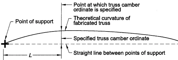
3.1.5. When camber is required, the magnitude, direction and location of camber shall be specified in the structural design documents.
Commentary:
For cantilevers, the specified camber may be up or down, depending upon the framing and loading.
(a) The identification of specific members or portions thereof to be painted. (b) The surface preparation that is required for these members.
(c) The paint specifications and manufacturer’s product identification, including color requirements, if any, that are required for these members.
(d) The minimum dry-film shop-coat thickness that is required for these members.
Commentary:
Some members or portions thereof may be required to be left unpainted, such as those that will be in contact and acting compositely with concrete, or those that will receive spray-applied fire protection materials.
3.2. Architectural, Electrical and Mechanical Design Documents and Specifications
All requirements for the quantities, sizes and locations of structural steelshall be shown or noted in the structural design documents. The structural design documents are permitted to reference the architectural, electrical and/or mechanical design doc-uments as a supplement to the structural design documents for the purposes of defining detail configurations and construction information.
When the referenced information is not available at the time of structural design, bidding, detailing or fabrication, subsequent revisionsshall be the responsibility of the ownerand shall be made in accordance with Sections 3.5 and 9.3.
3.3. Discrepancies
When discrepancies exist between the design documents and specifications, the design documentsshall govern. When discrepancies exist between scale dimensions in the design documents and the figures written in them, the figures shall govern. When discrepancies exist between the structural design documentsand the architec-tural, electrical or mechanical design documents, or the design documentsfor other trades, the structural design documents shall govern. When discrepancies exist between the design drawingsand the design model, the governing document shall be as identified per Section 1.4.
When a discrepancy is discovered in the contract documentsin the course of the fabricator’swork, the fabricatorshall promptly notify the owner’s designated rep-resentative for constructionso that the discrepancy can be resolved. Such resolution shall be timely so as not to delay the fabricator’swork. See Sections 3.5 and 9.3.
It is not the fabricator’sresponsibility to discover discrepancies, including those that are associated with the coordination of the various design disciplines.
3.4. Legibility of Design Drawings
Design drawingsshall be clearly legible and drawn to an identified scale that is appropriate to clearly convey the information.
Commentary:
smaller or larger scale is appropriate. Ultimately, consideration must be given to the clarity of the drawing.
The scaling of the design drawingsto determine dimensions is not an accepted practice for detailing the approval documents. However, it should be remembered when preparing design drawingsthat scaling may be the only method available when early-submission drawings are used to determine dimensions for estimating and bidding purposes.
3.5. Revisions to the Design Documents and Specifications
Revisionsto the design documentsand specificationsshall be made either by issuing new design documentsand specificationsor by reissuing the existing design docu-ments and specifications. In either case, all revisions, including revisions that are communicated through responses to RFIsor the annotation of the approval docu-ments(see Section 4.4.2), shall be clearly and individually indicated in the contract documents. The contract documentsshall be dated and identified by revisionnumber. When the design documentsare communicated using design drawings, each design drawingshall be identified by the same drawing number throughout the duration of the project, regardless of the revision. See also Section 9.3.
When revisionsare communicated using design models, revisionsshall be made evident in the revised design modelsubmitted by identifying within the design model which items are changed. Alternatively, the changes shall be submitted with a written document describing in explicit detail the items that are changed. A historic tracking of changes must either be present in the revised design modelor maintained in the written record of changes.
The party or entity that is contractually assigned responsibility for managing the design model shall maintain accurate accounting and tracking records of the most current design model, as well as previously superseded design models, and shall facilitate a tracking mechanism so that all contracted parties are aware of, and have access to, the most current design model.
Commentary:
Revisionsto the design documentsand specificationscan be made by issuing sketches and supplemental information separate from the design documents and specifications. These sketches and supplemental information become amendments to the design docu -mentsand specificationsand are considered new contract documents. All sketches and supplemental information must be uniquely identified with a number and date as the latest instructions until such time as they may be superseded by new information.
16.3-18 DESIGN DOCUMENTS AND SPECIFICATIONS
When revisions are communicated through the annotation of the approval docu mentsor contractor submissions, such changes must be confirmed in writing by one of the aforementioned methods. This written confirmation is imperative to maintain control of the cost and schedule of a project and to avoid potential errors in fabrication.
When design models are used, a similar unique method of identifying each revisionmust be used. This method can vary in various digital modeling software, but the same level of notation of changes must be present in the revised design model as would be used on design drawings.
3.6. Fast-Track Project Delivery
When the fast-track project delivery system is selected, release of the structural design documentsand specificationsshall constitute a release for construction, regardless of the status of the architectural, electrical, mechanical and other interfacing designs and contract documents. Subsequent revisions, if any, shall be the responsibility of the owner and shall be made in accordance with Sections 3.5 and 9.3.
Commentary:
The fast-track project delivery system generally provides for a condensed schedule for the design and construction of a project. Under this delivery system, the owner elects to release for constructionthe structural design documentsand specifica-tions, which may be partially complete, at a time that may precede the completion of and coordination with architectural, mechanical, electrical and other design work and contract documents. The release of the structural design documentsand specificationsmay also precede the release of the General Condi tions and Division 1 Specifications.
Release of the structural design documentsand specificationsto the fabricator for ordering of material constitutes a release for construction. Accordingly, the fabricatorand the erectormay begin their work based upon those partially complete documents. As the architectural, mechanical, electrical and other design ele ments of the project are completed, revisionsmay be required in design and/or construc-tion. Thus, when considering the fast-track project delivery system, the owner should balance the potential benefits to the project schedule with the project cost contingency that may be required to allow for these subsequent revisions.
3.7 Intellectual Property
SECTION 4. APPROVAL DOCUMENTS
4.1. Owner Responsibility
The ownershall furnish, in a timely manner and in accordance with the contract docu ments, the complete structural design documentsand specifications that have been released for construction. Unless otherwise noted, design documentsand speci -fications that are provided as part of the contract bid documents shall constitute authorization by the ownerthat the design documentsand specificationsare released for construction.
Commentary:
When the ownerissues design documentsand specificationsthat are released for construction, the fabricator and the erectorrely on the fact that these are the owner’srequirements for the project. This release is required by the fabricator prior to the ordering of material and the preparation and completion of the approval documents.
To ensure the orderly flow of material procurement, detailing, fabrication and erection activities, on phased construction projects, it is essential that designs are not continuously revised after they have been released for construction. In essence, once a portion of a design is released for construction, the essential ele-ments of that design should be “frozen” to ensure adherence to the contract price and construction schedule. Alternatively, all parties should reach a common understanding of the effects of future changes, if any, as they affect scheduled deliveries and added costs.
A pre-detailing conference, held after the structural steelfabrication contract is awarded, can benefit the project. Typical attendees may include the owner’s desig nated representative for construction, the owner’s designated representative for design, the fabricator, the steel detailer, and the erector. Topics of the meet-ing should relate to the specifics of the project and might include:
• Contract document review and general project overview, including clari-fications of scope of work, tolerances, layouts and sequences, and special considerations.
• Detailing and coordination needs, such as bolting, welding, and connection considerations, constructability considerations, OSHA requirements, coordina-tion with other trades, and the advanced bill of materials.
• The project communication system, including distribution of contact informa-tion for relevant parties to the contract, identificainforma-tion of the primary and alternate contacts in the general contractor’s office, and the RFIsystem to be used on the project.
• The submittal schedule, including the method of submitting (electronic or hard copy); for hard copy, how many copies of documents are required; connection submittals; and identification of schedule-critical areas of the project, if any. • If digital models will be used as part of the delivery method for the design docu
16.3-20 APPROVAL DOCUMENTS
such digital models, the transmission of digital models to prevent the loss or alteration of data, interoperability, and methods of review and approval. The term levels of development refers to the level of completeness of elements within the digital model (see the BIMFORUM Level of Development Specification). The term “authorized uses” refers to the permitted uses of the digital model(s) and the digital data associated with the digital model(s). Such authorized uses may include the right to (1) store and view the digital model(s) for informational purposes only, (2) rely upon, store and view the digital model(s) to carry out the work on the project, (3) reproduce and distribute the digital model(s) for informational purposes only, (4) rely upon, reproduce and distribute the digital model(s) to carry out the work, (5) incorporate additional digital data into the digital model(s) without modifying the data received to carry out the work on the project, (6) modify the digital model(s) as required to carry out the work on the project, (7) produce the digital model(s) in an archival format for the ownerto use as a reference for as-built construction data and/or for the operation of the project after completion, and/or (8) other authorized uses specified in the contract documents.
• Review of quality and inspection requirements, including the approvals process for corrective work.
Record of the meeting should be written and distributed to all parties. Subsequent meetings to discuss progress and issues that arise during construction also can be helpful, particularly when they are held on a regular schedule.
4.2. Fabricator Responsibility
4.2.1. Except as provided in Section 4.5, the fabricatorshall produce the approval docu-mentsfor the fabrication and erection of the structural steel and is responsible for the following:
(a) The transfer of information from the contract documentsinto accurate and com-plete approval documents.
(b) The development of accurate, detailed dimensional information to provide for the fit-up of parts in the field.
Commentary:
The fabricatoris permitted to use the services of independent steel detailersto produce approval documentsand to perform other support services, such as pro-ducing advanced bills of material and bolt summaries.
As the fabricatordevelops the detailed dimensional information for production of the approval documents, there may be discrepancies, missing information or conflicts discovered in the contract documents. See Section 3.3.