Pertemuan XXI, XXV :
PENGAKU
(
Stiffener
)
Mata Kuliah : Struktur Baja Kode MK : TKS 4019 Pengampu : Achfas Zacoeb
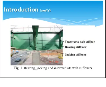
Stiffeners are secondary plates or sections which are attached to beam webs or flanges to stiffen them against out of plane deformations. Almost all main bridge beams will have stiffeners. However, most will only have transverse web stiffeners, i.e. vertical stiffeners attached to the web. Deep beams sometimes also have longitudinal web stiffeners. Flange stiffeners may be used on large span box girder bridges but are unlikely to be encountered elsewhere.
Fig. 1 shows an example of bearing, jacking and intermediate web stiffeners
Fig. 1 Bearing, jacking and intermediate web stiffeners
Introduction
(
cont’d
)
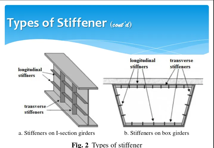
There are two principal types of stiffener as shown inFig. 2:
Longitudinal web stiffeners, which are aligned in the span direction
Transverse stiffeners, which are aligned normal to the span direction of the beam.
Transverse web stiffeners are usually provided at bearing positions and these are known as bearing stiffeners. For future maintenance it is good practice to provide bearing stiffeners at jacking points (for when girders have to be raised to free bearings for replacement). Other transverse stiffeners are called intermediate transverse web stiffeners.
Fig. 2 Types of stiffener
Types of Stiffener
(
cont’d
)
a. Stiffeners on I-section girders b. Stiffeners on box girders
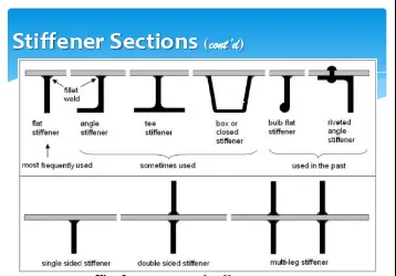
A variety of sections have been historically used as stiffeners, however the simple flat stiffener is the type almost always used in modern designs. Stiffeners can be attached on one side of the plate (single sided), or on both sides (double sided). Usually bearing stiffeners are double sided, while intermediate web stiffeners are single sided. Stiffeners can also be doubled up, or even trebled, to form multi-leg stiffeners. A typically of stiffener sections is shown in
Fig. 3.
Fig. 3. A typically of stiffener sections
Stiffener Sections
(
cont’d
)
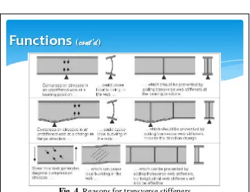
Stiffeners have one or both of the following functions:
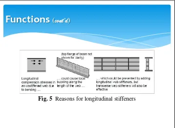
Controlling local buckling, as shown in Fig. 4 andFig. 5.
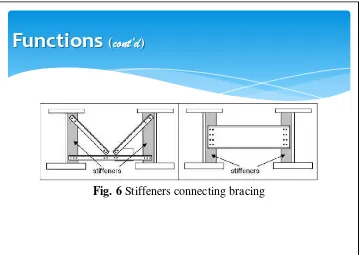
Connecting bracing or transverse beams, as shown in Fig. 6.
Controlling local buckling
Local buckling occurs when a cross section is slender enough for buckling to occur within the cross section, due either to compression or shear.
The webs of bridge beams are usually vulnerable to local buckling, but flanges are usually much thicker and inherently more resistant to buckling.
Local buckling can occur due to transverse compression load e.g. a web subjected to a bearing reaction, longitudinal compression load e.g. from bending, or from shear.
In all cases the addition of a relatively small stiffener to a slender plate can increase the resistance to local buckling substantially.
Functions
(
cont’d
)
Fig. 4 Reasons for transverse stiffeners
Fig. 5 Reasons for longitudinal stiffeners
Functions
(
cont’d
)
Connecting bracing or transverse beams
The easiest way to brace steel beams together is by fixing the bracing to transverse stiffeners.
Thus stiffener positions almost always coincide with bracing positions.
In a ladder deck the webs of transverse beams can be connected directly to the main beam stiffeners, so stiffener spacing matches transverse beam spacing.
In a multi-girder bridge with cross bracing the bracing members are usually connected to the main beam stiffeners, so that stiffener spacing is the same as bracing spacing.
Fig. 6Stiffeners connecting bracing
Functions
(
cont’d
)
Fig. 7Failure due to the lack of stiffeners
Design
There are two stages in the design of stiffeners:
1. The design needs to identify where stiffeners are needed for the main beams to be adequate.
2. Then the stiffeners themselves need to be designed.
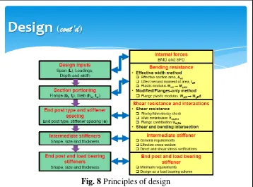
Basically, including plate girder principle design is shown inFig. 8.
Fig. 8 Principles of design
Types of Stiffeners
D
1.5
o
d D
1.5
o
d D
Bearing Stiffener Transverse Intermediate
Stiffener Longitudinal
Stiffener
Less than 6twor more than 4tw
Single Plate
Double Plate Angle
Bearing Stiffeners
Most bridge beams will require bearing stiffeners, even if bearing stiffeners are not required, they may still be provided if desired for giving a benefit the shear resistance.
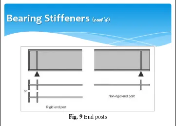
At end supports, if bearing stiffeners are to be provided, then a decision has to be made as to whether to provide a“rigidend post” or“non-rigid end post”as shown inFig. 9.
Note that multi-leg stiffeners must be split into separate effective cross sections and the loads divided between them.
Bearing Stiffeners
(
cont’d
)
Bearing Stiffeners
(
cont’d
)
Detailing:
At bearings, the stiffeners usually have to be quite substantial to resist the high compressive forces and may possibly have to be multi-leg stiffeners.
Usually a double sided stiffener is required to avoid a high eccentricity of loading.
Bearing stiffeners are usually thicker than the web.
It is important to make sure the stiffener is “fitted” to the bottom flange, which means the stiffener is ground to make good contact with the flange (it means the stiffener's share of the axial force in the effective stiffener section can be transmitted through direct contact between the flange and stiffener.
Bearing Stiffeners
(
cont’d
)
A simple way to determine the stiffener's share of the axial force is to calculate the stress at its centroid, taking into account eccentricity of axial force on the effective section, and then multiply this stress by the stiffener area.
Welds are almost always continuous fillet welds all round both sides of the stiffener.
A simple 6mm leg length weld may be adequate but often may have to be 8mm or 10mm.
Intermediate Stiffeners
It is usually necessary to provide intermediate stiffeners on main beam webs for the practical purpose of connecting torsional bracing between the beams.
The chosen bracing positions will determine the positions of at least some of the stiffeners, for beams with no bracing , such as transverse girders in a ladder deck bridge, or if plan bracing is being used, there may be no practical necessity for intermediate stiffeners at all.
The requirement for intermediate transverse web stiffeners is determined by the verification of the shear resistance - this will indicate where stiffeners are needed, and where stiffeners extra to those for bracing are needed.
Intermediate Stiffeners
(
cont’d
)
As a first step in design, it is suggested that initially is assumed there are no intermediate stiffeners at all, it proves the beam to be adequate in shear then the benefit of any intermediate stiffeners for bracing attachment will be a bonus.
If the first procedure determines that intermediate stiffeners are required, then the designer will need to choose the positions and spacing of these stiffeners, and to decide whether they need to be rigid.
Intermediate Stiffeners
(
cont’d
)
For example, in a ladder deck bridge, the shear in the transverse beams will cause an axial force in the main beam stiffener (it may also be horizontal loading to consider from the bracing which may generate bending moments in the stiffener section).
Having determined the loading, verify the chosen stiffener size by checking the adequacy of the effective stiffener section to act as a column for combined axial force and bending moment (if any).
If there is no direct loading on the stiffener from any of the above, it is only necessary to ensure the effective stiffener section satisfies the stiffness criterion given in codes*.
*)SNI 03-1729-2002:Tata Cara Perhitungan Struktur Baja untuk Bangunan Gedung
Intermediate Stiffeners
(
cont’d
)
Detailing:
For intermediate transverse web stiffeners, the stiffener probably does not need to be very big, typically a single sided 150x15mm plate has adequate strength and stiffness.
Sometimes the stiffener size will have to be increased to accommodate connections, it can be done by increasing the plate size to 200G20mm or perhaps 250G5mm or alternatively it can be locally increased to provide connection area.
Intermediate Stiffeners
(
cont’d
)
However, there are no restriction on this ratio, and more slender stiffeners are permitted, although checks may need to be made that they will not be at risk from local buckling.
It does not matter if the stiffener is thicker than the web, so generally thicker stiffeners are recommended.
To give a clean appearance to the bridge, it is normal to design the outer beams such that the intermediate transverse stiffeners are on the inner face of the web and hence not visible on the elevation.
Unless there is a substantial axial force on the stiffener, a simple weld detail such as a 6mm leg length continuous fillet weld all round both sides of the stiffener should be sufficiently strong and durable.
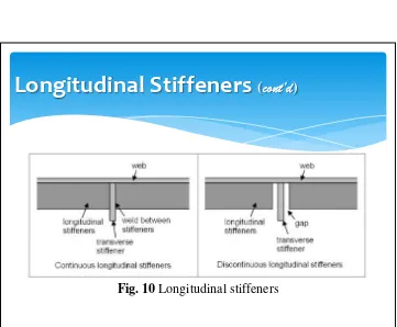
Longitudinal Stiffeners
As noted before, most bridges do not have longitudinal stiffeners.
To determine if longitudinal stiffeners are required on the web to give the main beams sufficient shear strength, the procedure is as for intermediate stiffeners, i.e. to verify the shear resistance of the beam.
Longitudinal Stiffeners
(
cont’d
)
Discontinuous longitudinal stiffeners stop and start again either side of the transverse stiffener so that they do not pick up global longitudinal stresses from the web or flange to which they are attached (they are there simply to resist buckling to the web or flange).
Continuous longitudinal stiffeners, however, do pick up global stresses and add to the cross section.
If longitudinal stiffeners are to be provided they are to be verified by checking the adequacy of the effective stiffener section to act as a column.
Longitudinal Stiffeners
(
cont’d
)
Connections
Transverse web stiffeners are sometimes welded to the flange, and sometimes stopped just short of either or both flanges.
The necessity for a connection to a flange depends on whether forces need to be transferred to the flanges.
If there is a significant axial force to be transferred to the stiffener from one of the flanges it will be necessary to weld the stiffener to that flange.
Hence bearing stiffeners must be connected to the bottom flange if part of the bearing reaction is to be transferred to the stiffener.
If there is bracing connected to the stiffener then it is likely that it is necessary to weld the stiffener to the compression flange to transfer the lateral shear force.
A connection to the top flange also prevents a fatigue problem in the top flange to web weld as the deck tries to rotate over the beam due to traffic loads.
The advantage of stopping the stiffener short of the flange is that it avoids a potential water trap on the upper surface of the bottom flange (it is particularly important to avoid on weathering steel bridges).
A typically of connection to the flange as shown in Fig. 11 and
Fig. 12.
Connections
(
cont’d
)
Fig. 11Stiffener to flange connections
Connections
(
cont’d
)
Connections
(
cont’d
)
Where a stiffener is to be welded to a flange, normal construction tolerances would result in a small gap between the stiffener and the flange, unless the stiffener is fitted; all the forces will therefore be transferred through the welds.
However, if a stiffener is fitted to the flange, the fabricator will grind the stiffener end so as to make a good fit with the flange over a substantial proportion of the stiffener area as shown inFig. 13.
This exercise requires additional work (and cost) so stiffeners should only be fitted when necessary, e.g. for bearing stiffeners and for stiffeners at a change in flange direction.
Connections
(
cont’d
)
Snipe and Cope Hole
At the corner of a transverse web stiffener where the stiffener plate meets the web to flange weld, it will be necessary to shape the stiffener to avoid the weld.
There are two options, either snipe the stiffener to suit the web to flange weld and weld up all the interfaces, or provide a cope hole as shown inFig. 14.
Although the first option requires welding one weld on top of another, this detail may be easier to fabricate than the second, because it is difficult to satisfactorily complete continuous welds around cope holes and apply paint to all of the surfaces.
Snipe and Cope Hole
(
cont’d
)
Typically of Plate Girder
Fig. 15Unstiffened and stiffened plate girders
Typically of Plate Girder
(
cont’d
)
Typically of Plate Girder
(
cont’d
)
Fig. 16Plate girder cross sections
Typically of Plate Girder
(
cont’d
)
Typically of Plate Girder
(
cont’d
)
Fig. 18Plate girder with hole for services
TERIMA KASIH
DAN