NPTEL – Chemical – Mass Transfer Operation 1
Joint initiative of IITs and IISc – Funded by MHRD Page 1 of 4
MODULE 4: ABSORPTION
LECTURE NO. 2
Design of packed tower
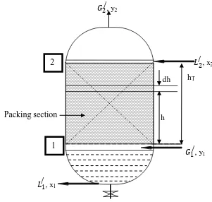
The cross sectional view of the packed tower is shown in Figure 4.5.
Design of packed tower may be
(I) on the basis of individual mass transfer coefficients or (II) on the basis of overall mass transfer coefficient.
Figure 4.5: Cross sectional view of packed tower.
The column is packed with packing materials (any type) to provide more contact between gas and liquid.
hT dh
�1 /
, y1 �2
/
, x2 �2
/
, y2
1 2
�1 /
, x1
NPTEL – Chemical – Mass Transfer Operation 1
Joint initiative of IITs and IISc – Funded by MHRD Page 2 of 4 Let, G/and L/ are gas and liquid flow rate per unit area basis, mol/h.m2. ā is specific interfacial contact area between gas and liquid, m2/m3. The mole fraction of solute in gas is y.
Hence, solute flow rate in gas= G/y mol/h.m2
The decrease in solute flow rate over the thickness
dh=d(G/y) (4.1)
For a unit cross-sectional area (1m2), volume of differential section=1×dh m3 and interfacial area of contact in differential section= ā×1×dh m2
If NA is solute flux and ky is individual gas-phase mass transfer coefficient, solute
transfer through differential section= ā×dh×NA.
Therefore,
Integration of Equation 4.6 gives the height of packed column as follows:
ℎ� = �ℎ0ℎ� =−
Interfacial solute concentration, yi is not known; hence the integration of the right
NPTEL – Chemical – Mass Transfer Operation 1
Joint initiative of IITs and IISc – Funded by MHRD Page 3 of 4
STEP-BY-STEP PROCEDURE
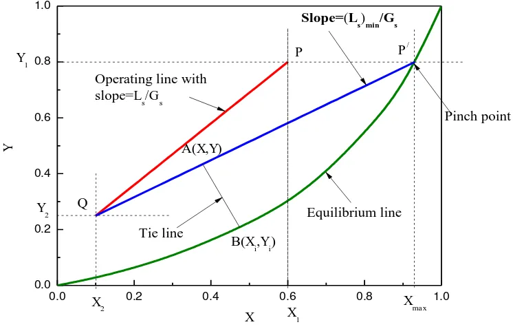
(1) For a particular gas-liquid system, draw equilibrium curve on X-Y plane. (2) Draw operating line in X-Y plane (PQ) using material balance Equation. Lower terminal Q (X2, Y2) and upper terminal P (X1, Y1) are placed in x-y plane.
Overall mass balance Equation for the absorption tower is as follows: �� 1− 2 =�� 1− 2
Figure 4.6: Graphical determination of (Ls)min for absorption.
In Figure 4.6, lower terminal of absorption tower is represented by Q (X2,
Y2); i.e., bottom of the tower. Operating line is PQ. If liquid rate is decreased,
slope of operating line (Ls/Gs) also decreases and operating line shifts from PQ to
P/Q, when touches equilibrium line. This operating line is tangent to equilibrium
NPTEL – Chemical – Mass Transfer Operation 1
Joint initiative of IITs and IISc – Funded by MHRD Page 4 of 4
Slope of / = (��) � ��
The driving force for absorption is zero at P/ and is called “PINCH POINT”. (3) A point A (x, y) is taken on the operating line. From the known value of kx
and ky or kxā and kyā, a line is drawn with slope of kx /ky to equilibrium line,
B(xi,yi). Line AB is called “TIE LINE” and xi and yi are known for a set of values of
x and y.
(4) Step (3) is repeated for other points in the operating line to get several (xi,yi) sets for y1≥y≥y2.
(5) Calculate flow rate of gas G (kg/h) at each point as G=Gs(1+y).
(6) Calculate height of the packing hT of Equation 4.7 graphically or
numerically.
The height of the „stripping column‟ is also obtained in a similar way. For stripping, y2>y1 and driving force is (yi-y). The corresponding design Equation will
be
ℎ� = �
/� � 1− � ( �− )
2