Numerical Study of Structural Integrity and Strain
Response of Double End Beam Load Cell Using
Finite Element Simulation
Hilman Syaeful Alam
Technical Implementation Unit for Instrumentation Development, Indonesian Institute of Sciences, Jl. Sangkuriang Komplek LIPI Gedung 30 Bandung, 40135, Indonesia
Abstract—Finite element simulation had been used to assess the structural integrity and strain response of double end beam load cell. The purpose of the study is to analyze the mechanical strength and to predict the class of measurement accuracy of the load cell design before manufacturing the physical prototypes. Based on the analysis of structural integrity, safety factor of the structure was still in acceptable limits therefore the structure would certainly secure against both plastic deformation and ultimate failure. Then based on the strain simulation results, the level of measurement accuracy was predicted to reach the medium class with a good repeatability of measurement.
Keywords—finite element; load cell; structural integrity; strain response; accuracy
I. INTRODUCTION
The speed and capability of modern computers had increased between one thousand to ten thousand times in the past twenty years. It has triggered a very rapid progress in computer simulation technology based on numerical analysis. Nowadays, this simulation technology has been applied into a lot of engineering application such as flow simulation on the geological structures 0, dynamic analysis of risers in offshore application [2], temperature distribution analysis of photovoltaic module [3], surface roughness analysis of a rectangular tube [4], prediction of the damage progression in composite structure [5], crack analysis of a tire in automotive application [6], sound field analyses of sound absorbing material [7], thermal analysis of thermoelectric power generator [8], and so on.
The underlying method of the computer simulations applied to all the previous studies above is the finite element method (FEM). The basic concept of the FEM is a division of the continuously object or system into small elements which much simpler called finite elements, accompanied by polynomial approximation for each elements between the points that connect each element of the system called nodal point [9]. Each continuous solution such as stress, deformation, temperature, pressure and others can be approximated by a discrete model consisting of a collection of continuous functions that defined throughout the element [10]. In the field of product design, designers use the finite element by build three-dimensional geometric models of the mechanical system to simulate its
performance (such as deformation, stress, vibration and so on) before manufacturing the physical prototype. Several advantages of numerical simulation on the product design are to reduce the manufacturing cost of physical prototypes, to shorten the time and to reduce the cost of product development [12].
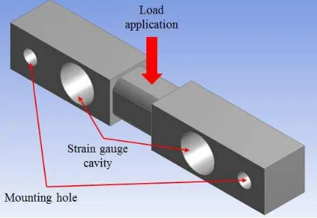
In this study, finite element simulation was applied to assess the structural integrity of the double-end beam load cell as one of the requirements in the design process. Double end beam load cell is a kind of force measuring instrument which is popular and widely applied for truck scales and tank and hopper applications. This instrument is designed to change the force measurement into an electrical signal, which the force on the structure is measured by strain gauge and converted into electrical quantities [13]. Fig. 1 shows the construction of double ended beam load cell. The load applied to the center of the load cell is secured at both ends with the mounting hole. As one of the shear beam load cell, the strain gauges are mounted in the center of the cell’s structured cavity. The analysis of strain can’t be done via simple hand calculation due to the structural complexity of double end beam load cell, hence the finite element simulation is used to analyze the strain response due to loading on the structure in order to predict the class of measurement accuracy.
Fig. 1 Structure of double end beam load cell
2015 International Conference on Automation, Cognitive Science, Optics, Micro Electro-Mechanical System, and Information Technology (ICACOMIT), Bandung, Indonesia, October 29–30, 2015
II. MATERIALS AND METHODS A. Strain Mechanism of Load Cell
According to Marchidan et al. [13], strain due to the deformation of the load cell structure is measured using strain gauge which has a variable electrical resistance. Wheatstone bridge circuit is used to turn resistance into voltage that is proportional to the resistance or the output signal of the strain gauge. Fig. 2 shows the strain measurements that are converted into electrical voltage using 4 pieces of strain gauge through a Wheatstone bridge circuit. Strain gages should be placed on four regions that have a high strain, due to ensure the repeatability of measurement on both tensile and compressive measurements (T1 and T2: tensile strain areas, C1 and C2: compressive strain areas), therefore the total strain can be calculated as follows:
� �� = �� − �� + �� − �� (1)
Fig. 2 Wheatstone bridge circuit [14]
When subjected to the loading, the output signal of the bridge will equivalent and linear with the applied load. Signal amplifier is required to provide an excitation input voltage �
then after the equilibrium state, it will produce an output voltage
� in micro strain. One factors affecting the level of measurement accuracy of the load cell is the strain amount on the structure which depends on the specifications of the strain gauge. In this study, the commercial strain gauge is planned to be use to convert mechanical strain into electrical signal which has the specification in Table 1. In order to determine the strain gauge installation position on the structure cavity, a detailed analysis based on finite element modeling needs to be performed due to the structural complexity of the double end beam load cell.
Table 1 Specification of Strain gauge & adhesive [15].
Accuracy class Maximum
There are three equations which are required for modeling the load cell, i.e. an equilibrium balance, a constitutive relation
relating stress and strain, and a kinematic relation relating displacement to strain [14]. Newton’s second law serves as the equilibrium equation, which in tensor form is:
∙ � + � = ��̈ (2)
where � is stress, � is body force per volume, �is density, and �̈ is acceleration. For static analysis, the right-hand side of this equation goes to zero.
The constitutive equation relating the stress tensor � to strain � is generalized by Hooke’s law:
� = � ∶ � (3)
where � is the fourth-order elasticity tensor and ∶ denotes the double dot tensor product. This relation can be expanded to:
� − � = � ∶ � − � − � �� (4)
In this study, the initial stress �, initial strain � , and inelastic strain � �� are all zero. For isotropic material, the elasticity
tensor reduces to the 6X6 elasticity matrix:
is elastic modulus and is Poisson’s ratio of the material. In this study, a double end beam load cell is made using AISI 4340 material that has mechanical properties in Table 2.
Table 2. Mechanical properties of AISI 4340 [17].
Parameter
Tensile strength 745 MPa
Yield strength 470 MPa
Elastic modulus 190-210 GPa Poisson ratio 0.27-0.30
where denotes the tensor transpose. For rectangular Cartesian coordinates the strain tensor may be written in indicial notation:
� = [�� +�� −� �
� � �
� ] (9)
� = [�� +�� ] (10)
where � [ , ]
B. Structural Integrity of Load Cell
According to Zienkiewicz & Taylor [11], the general forms of the equation in solving problems of the stress � and strain �
for the continuum structure based on the calculation of stress matrix element in elastic region can be stated as follows:
� =
{ � � �
}
= �� (11)
where D is the elasticity matrix based on the material's elastic constants..
The structural integrity of the load cell is based on the yield criterion of the material due to the principal stresses on the structure. Based on the theory of energy distortion [16], the equivalent (Von Mises) stress, can be calculated as follows:
��= √(� −� ) 2
+(� −� )2+ � −� 2+6( 2+ 2+ 2) (12) The failure based on the yield criterion of the material can stated as follows:
��≤ (13)
and the failure due to ultimate load until fracture is as follows:
��≤ � (14)
where is the yield strength and � is the ultimate strength of material.
C. Finite Element Simulation
In this study, ANSYS was utilized to perform finite element simulations to analyze the structural integrity and strain response of a double end beam load cell. The initial step of the finite element simulation is modeling of 3 Dimensional (3D) geometry of the structure which was analyzed for homogeneous and linear elastic with AISI 4340 material. The next step in the simulation is discretization or meshing. Meshing is a division the solid model of the structure into small elements which are analyzed according to the material properties, boundary conditions and loading. Meshing process is performed using tetrahedral element types which are shown in Fig. 3. Meshing process produced 12,047 tetrahedral elements and 21,466 nodes.
Fig. 3 Meshing of double end beam load cell. After meshing, the next step is to determine the boundary conditions and loading. The mounting holes at the left and right side of this beam were defined as a fixed constraint boundary. The load was applied to the center of the beam as a point load in accordance with the maximum capacity of measurement i.e. 20 kN. The last step of the simulation is the calculation and displaying the desired results.
III. RESULTS AND DISCUSSIONS
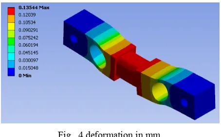
After going through the iterations and calculations, the finite element results can be determined for each segment of the structure. Fig. 4 shows a deformation at 20 kN of maximum loading. The amount of maximum deformation is 0.13544 mm, where the location is in the center part of the structure which is marked in a red graph, while on both mounting hole at the right and left side of the structure, it doesn’t occur deformation due to fixed restraint boundary.
Fig. 4 deformation in mm.
Fig. 5 Von Mises stress in MPa
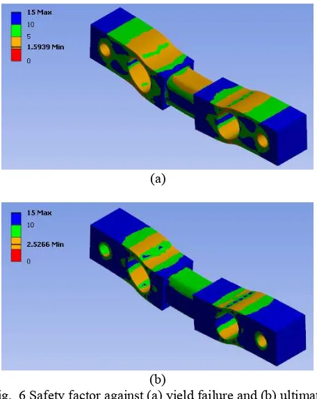
Based on the mechanical properties of AISI 4340 (Table 2), the amount of yield strength and tensile strength of the material is 470 MPa and 745MPa respectively or greater than the maximum equivalent stress on the load cell structure therefore the structure will be safe on both plastic and ultimate of the material. Safety factor distribution in each segment of the load cell structures to yield failure can be seen in Fig. 6 (a), which the minimum safety factor is 1.5939 located at the mounting holes, strain gauge cavity and loading position. While safety factor to ultimate failure can be seen in Fig. 6 (b) with the minimum safety factor is 2.5266.
(a)
(b)
Fig. 6 Safety factor against (a) yield failure and (b) ultimate failure.
Besides being able to determine the structural integrity of the load cell, finite element simulation is able to describe the strain response due to loading which is used as a reference of strain gauge placement and prediction of the level of measurement accuracy. Fig. 7 shows the strain response due to loading. There are two areas that have the highest tensile and compressive
strain at each strain gauge cavity of the structure. The highest tensile strain is 0.0012899 mm/mm or almost reaches 1300 �, while the highest compressive strain is -0.0012679 (-1300 �). It can be inferred that strain gauge cavity both left side and right side of the beam is symmetrical therefore it is suitable for strain gauge placements to ensure the repeatability of measurements. The level of measurement accuracy is predicted to reach the medium class by using the appropriate type of strain gauge and adhesive.
Fig. 7 Strain response due to loading in mm/mm
IV. CONCLUSSIONS
Finite element simulation was capable of displaying the detailed analysis results of each segment in three-dimensional structure of the load cell. Based on the analysis of structural integrity, the equivalent stress due to the maximum loading on the structure had a value which was lower than the yield and ultimate strength of material therefore the structure will certainly secure against both plastic deformation and ultimate failure because it was still in the area of elastic material. Then based on the strain simulation results, the level of measurement accuracy was predicted to reach the medium class with good repeatability of measurement, because both compressive and tensile strain was almost symmetrical for the two locations of the strain gauge mounting hole i.e. the left and right side of the beam. However the experimental investigation is needed to validated the simulation results.
ACKNOWLEDGMENT
The author would like to thank to the Head of Technical Implementation Unit for Instrumentation Development, Indonesian Institute of Sciences which has provided a financial support through LIPI research thematic in 2015 (No. 07901450196013). Moreover thanks to the Head of Research Center for Power and Mechatronics, Indonesian Institute of Sciences, for facilitating the finite element simulation using ANSYS.
REFERENCES
[1] B. Zehner, J. H. Börner, I. Görz, K. Spitzer, “Workflows for generating tetrahedral meshes for finite element simulations on complex geological structures,” Computers & Geosciences, Vol. 79, pp. 105–117, 2015. [2] I. A. Wójcik, L. Brzozowska, Ł. Drąg, “An analysis of dynamics of risers
[3] J. Zhou, Q. Yi, Y. Wang, Z. Ye, “Temperature distribution of photovoltaic module based on finite element simulation,” Solar Energy, Vol. 111, pp. 97–103, 2015.
[4] L. Zhang, W. Xu, J. Long, Z. Lei, “Surface roughening analysis of cold drawn tube based on macro–micro coupling finite element method,” Journal of Materials Processing Technology, Vol. 224, pp. 189–199, 2015.
[5] A. M. G. Coelho, J. T. Mottram, K. A. Harries, “Finite element guidelines for simulation of fibre-tension dominated failures in composite materials validated by case studies,” Composite Structures, Vol. 126, 299–313, 2015.
[6] J. Cho, S. Lee, H. Y. Jeong, “Finite element analysis of a tire using an equivalent cord model, Finite Elements in Analysis and Design,” Vol. 105, pp. 26–32, 2015.
[7] T. Okuzono, K. Sakagami, “A finite-element formulation for room acoustics simulation with microperforated panel sound absorbing structures: Verification with electro-acoustical equivalent circuit theory and wave theory,” Applied Acoustics, Vol. 95, pp. 20–26, 2015. [8] G. Wua, X. Yu, “A holistic 3D finite element simulation model for
thermoelectric power generator element,” Energy Conversion and Management, Vol. 86, pp. 99–110, 2014.
[9] D.V. Hutton, Fundamental of Finite Element Analysis, The McGraw Hill Company USA, pp. 1-50, 2004.
[10] G. R. Liu and S. S. Quek, The Finite Element Method: A Practical Course, Oxford: Butterworth-Heinemann, Elsevier Science Ltd, 2003.
[11] O.C. Zienkiewicz and R.L. Taylor, The Finite Element Method Fifth Edition Volume 1: The Basis, Oxford: Butterworth-Heinemann, Elsevier Science Ltd, 2000.
[12] G. Zhang and N. Zhou, “Study on Integrated Design Method for Series Traction Mechanism of Heavy Machinery Based on Virtual Prototyping,” Physics Procedia, Vol. 25, pp. 2 – 7, 2012.
[13] Ricelake Weighing System, Load cell and Weigh Module Handbook,
http://www.ricelake.com/docs/prodinfo/Manuals/load-cells/lch_22054.pdf. [Accessed 2 Februari 2014].
[14] A. Marchidan, T. N. Sullivan dan J. L. Palladino (2012). Load Cell Design Using COMSOL Multiphysics, The Proceedings of the 2012 COMSOL
Conference, Boston.
https://www.comsol.com/paper/download/150701/palladino_paper.pdf, [Accessed 5 March 2014].
[15] Technical Note TN-505-4. 2010, Strain Gage Selection: Criteria, Procedures, Recommendations, Vishay Precision Group, www.micro-measurements.com, [Accessed 5 March 2014]
[16] E. P. Popov, Mechanics of Material 2nd Edition, Erlangga, Jakarta, 1990. [17] The mechanical properties of annealed AISI 4340 alloy steel, Available
![Fig. 2 Wheatstone bridge circuit [14]](https://thumb-ap.123doks.com/thumbv2/123dok/264501.506096/2.595.74.260.237.399/fig-wheatstone-bridge-circuit.webp)