Active Suspension System based Lyapunov Method
and Ground-hook Reference Model
Ayub Wimatra, Sunardi,
Julfansyah Margolang, Edi
Sutrisno
Academy of Engineering and Flight Safety,
Medan, Indonesia
Emails: [email protected], [email protected],
[email protected], [email protected]
Darmeli Nasution, Suherman Faculty of Computer Science Universitas Pembangunan Panca
Budi Medan, Indonesia
E-mails:
[email protected], [email protected]
Taufik Hidayat, Arjon Turnip
Technical Implementation Unit forInstrumentation Development Indonesian Institute of Sciences,
Bandung, Indonesia E-mail: [email protected]
Abstract— An alternative design technique for active suspension system of vehicle using a developved ground-hook damping system as a reference is proposed. The controller parameters are determined using Lyapunov method and can be tuned to precisely achieve the type of desired response which given by reference model. The simulation result show that the designed active suspension system based ground-hook reference model is able to significantly improve the ride comfort and the road holding compared with semi-active suspension.
Keywords—suspension; quarter-vehicle; adaptive control; model reference; Lypunov
I. INTRODUCTION
In recent years there has been a significant growth in the design of suspension systems by which should reduce vibration due to the external disturbances to the maximum possible degree [1-16]. Two criteria of good vehicle suspension performance are typically their ability to provide good road handling and increased passenger comfort. It is difficult to meet both requirements, since this involves opposing tendencies in the selection of the main parameters of suspension, i.e. stiffness and damping. Suspension should be rigid enough to effectively carry the static load, and soft enough to ensure the good isolation of vibrations. These two factors are related to the body vertical acceleration and the suspension deflection. If the suspension system is unable to absorb the vibration caused by the unevenness of the road surface, a significant deflection of the suspension will occur resulting unsafe condition of the vehicle. Moreover, the sprung mass of the vehicle will also exhibit a large vertical acceleration which can be the reason of a ride discomfort. In order to achieve a good ride quality, the performance of the suspension system plays an important role.
Since most of the vehicle suspensions do not operate with a single well defined roadway input, real suspensions are rarely optimal for any particular road and speed. On smooth roads the suspension will be stiffer than necessary and on rough roads
softer that desirable. This leads to the concept of an adaptable suspension which can change its characteristics bases on measured performance. By using an adaptation algorithm, it is expected that the optimal performance can be maintained over the wide range of input conditions typically encountered by a vehicle. In this paper, an alternative design technique for active suspension system of vehicle using adaptive controller based skyhook damper model is proposed. The reference model and the controller systems are designed and determined using skyhook model and Lyapunov method, respectively. The control design was applied to two different suspension models, namely the body vertical acceleration and the suspension deflection models, each representing comfort and safety factors.
II. DYNAMIC OF SUSPENSION SYSTEM
A. A QuarterActive Model of Suspension System
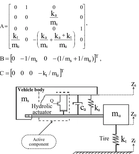
In most cases, dynamic systems are stimulated by the movement of anchorages. The suspension system of car is stimulated as a result of moving on the ruggedness of the road. A car is moving on a bumpy road in which some forces are exerted on the passengers as the result of the change of the length of springs and dampers. The schematic diagram of a quarter-vehicle suspension system under investigation can be presented as in Fig. 1, where ms and mu each represents the sprung mass and unsprung mass respectively, ca represents absorber coefficient, ka represents spring constants, kt represents the tire equivalent constants, zr represents surface roughness of road, zs represents vehicle body position and zu represent the tire vehicle position. The variable Q represents an applied actuator force for the active suspension. The values of the parameters in this model, which are taken from a typical passenger car, are collected in Table 1. However, the value of
a
k is unknown therefore it can be assumed that there is no limitation in generating the actuator force Q. Using Newton’s second law, the equations of motion for the model in Fig. 1 are given by
2015 International Conference on Automation, Cognitive Science, Optics, Micro Electro-Mechanical System, and Information Technology (ICACOMIT), Bandung, Indonesia, October 29–30, 2015
z z Q kz
mss a s u (1)
z z
k z z Qk z
muu a s u t( u r) . (2)
By defining x1zs, x2zs, x3zszu, and
u s z
z
x4 , then the equations (1) and (2) can be expressed in the state space form as follows:
r
Cz Bu AX
X (3)
wh ere, the matrices A, B, and C are given by
0 0 1 0 0 0 0 0 0 0 0 1 0
m
k
k
m
k
m
k
m
k
u t a s a u t s a A ,
Tu s
s m m
m
B 0 1/ 0 (1/ 1/ ) ,
Tu t m
k
C 0 0 0 /
Hydrolic actuator Vehicle body
m
sm
uk
t Qz
sz
uz
r Active component Tirek
aca
Fig. 1 Schematic diagram of a quarter-vehicle model
Table 1. System parameters.
Parameter Value
Sprung mass (m ) s 412.5 kg
Unsprung mass (m ) u 51 kg
Tire stiffness (k ) t 210 N/m
Rattle space (zszu)max 91 mm
B. A Ground-hook Damper as Reference Model
In order to specify the desired performance of the suspension system, the reference model is derived from quarter-vihicle ground-hook model (see Fig. 2). Ground-hook proposed the control method Ground-hook that in which an assumed amortize has been incorporated between the sprung mass and the ground in order to reduce dynamic force of tire and to improve the conductibility of the car. In Fig. 2, The linear equation of the state for reference model Ground-hook from the order of four has been presented as follows:
) ( )
( s u s u
b s
sz k z z c z z
m (4)
) ( ) ( )
( s u g u s u t1 u r
b u
uz k z z c z c z z k z z
m (5)
where, c and b cg are indicate a variable damper and a
coefficient that connected between the unsprung mass and the fixed fictitious frame on the ground, respectively. zs, zu,
u s z
z are the velocities of sprung mass, unsprung mass, and relative velocity between sprung mass and unsprung mass. Theoretically, ground-hook damper model will improve the responses of the unsprung system [18]. The ideal ground-hook damper model is given by: if zu(zszu)0 then f cgzu,
if zu(zszu)0 then f 0, where f is ground-hook damper model force. The generated forces by the ground-hook model are added to the passive vehicle model which used as a reference on acttive suspension controller design.
Fig. 2 Ground-hook reference model of a quarter-vehicle suspension system
In the state space form, equations (4) and (5) is written as
r d d d
d A X C z
X (6)
where the matrices A and d C are given by d
u b s b u t b s b u g s g u t s b s b s g d m c m c m k k m k m c m c m k m c m k m c A 1 1 1 0 0 0 / / / 0 0 0 1 0
Tu t
d k m
C 0 0 0 1/ .
III. CONTROLLER DESIGN
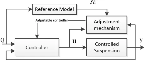
different or the error, e is used to generate an actuating signal. One of most critical point in the design is how to make the error e as small as possible. This will depend on the model, the system, and the command signal. If it would be possible to make the error equal to zero for all command signals, then perfect model-following would be achieved.
Reference Model
Controller Controlled
Suspension Adjustment mechanism
Adjustable controller
d y
y
u
Q
Fig. 3 The scheme of active suspension system based lyapunov method and ground-hook reference model
As shown in Fig. 3, a feedback adaptive controller whose parameters were adjusted by an adaptive law based on the measurement of the error. Choosing the control law as follows:
X
Q , (7)
where
[
1
2
3
4] is an adjustable controller gain matrix, then equation (3) becomes
A B
X CzrX
. (8)Assumed that CCd, then the error and its dynamic between
the states in Fig. 3 can writen as
d
X X
e . (9)
X B A A e A X X
e d d ( d
) (10)In order to make e goes to zero, then there must be exist a set of unknown constant gain
* such thatd
A B
A
* . (11)By substituting (11) into (10), we have
X B e A
e m (12)
where *. In order to drive the adjustment law of the parameter, the Lyapunov function is introduced as
eTPe T
V
2 1
(13)
eTPe eTPe T
V 2
2 1
(14)or
T T T T
d T d
T A P PA B PeX
e
V
2 1
(15)
By chosing
BTPeXT, then equation (15) can be simplify ase e V T
2 1
. (16)
Then the parameter adjustment law is obtained as
T T T pB PeX
B
. (17)IV. DISCUSSIONS
To investigate and observe the performance of the designed adaptive controller to changing dynamics of the vehicle suspension systems, two different types of input signals (i.e., sinusoid and random signals) representing different types of road to stimulate the dynamics of suspension of the vehicle have been identified. It is desired that when the vehicle runs on the three different road types, the controller will choose the coefficients of controller such that the closed-loop output response of each model will be close to the model-reference response for any changes of the dynamic suspension system.
Revisiting the ground-hook scheme in Fig. 2, the variables
b
c and cg define the control gains that are used in computing
u in proportion to
z
s
z
u and zu. Fig. 4 shows that, as the damping coefficients c and 1 c (to indicate 2 c and b c , grespectively) increases, the peaks of the accelerations of the sprung and the unsprung masses at their natural frequencies decrease, while the acceleration levels in the frequency range 4-8 Hz and in the frequency range 12 Hz and higher increase. Decreasing c while increasing b c results in an increase of the g
amplitude of the unsprung-mass natural frequency, with the gain of the reduction of the amplitude of other frequency ranges. Another notable observation is that the transmissibility to the sprung-mass acceleration with constant c in the higher b
frequency range of over 12 Hz is constant for any value of c . g
The dynamic response of the system for different values of the damping coefficients is clearly a weighted combination of the damping coefficients of the skyhook control. The controlled skyhook then is used as reference model in the adaptive controller design.
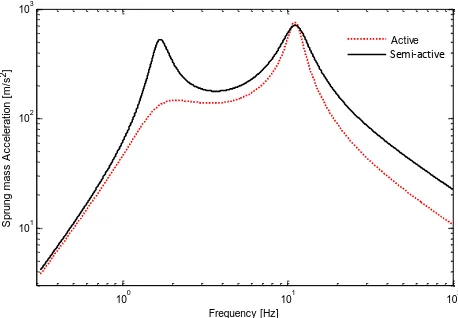
noise & harshness in the frequency range of 12 Hz and higher, when compared with the passive suspension. Fig. 6 and 7 show the comparison of output responses between the desired reference model with output response of the controlled suspension model which dynamic has changed during vehicle running, each for body vertical acceleration model and suspension deflection model respectively.
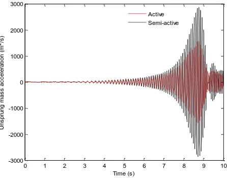
If the results between semi-active and active suspension systems are compared in Figs. 6-8, it can be seen that, for the same input road disturbance in the form of random, the output response of semi-active suspension will follow the disturbance, whereas for the active suspension using the designed model reference adaptive technique then the output response does not react accordingly to the disturbance. This means that the designed active suspension performs better than the semi-active one when the vehicle is subject to different road disturbance. In Fig. 6 it can also be observed that the output response of the controlled suspension will follow almost exactly the output of the reference model.
100 101 102
101 102 103
Frequency [Hz]
S
p
ru
n
g
m
a
s
s
A
c
c
e
le
ra
ti
o
n
[
m
/s
2]
c1=4000, c2=4000 c1=3000, c2=4000 c1=2500, c2=4000 c1=2000, c2=4000 c1=1000, c2=4000 Passive:c1=2000, c2=0
.
Fig. 4 Comparison of the magnitude plots of the frequency responses of
z
s(
s
)
/
z
r(
s
)
for various damping coefficients.100 101 102
101 102 103
Frequency [Hz]
S
p
ru
n
g
m
a
s
s
A
c
c
e
le
ra
ti
o
n
[
m
/s
2]
Active Passive
Semi-active
Fig. 5 Comparison of the frequency responses of
)
(
/
)
(
s
z
s
z
s r
.0 1 2 3 4 5 6 7 8 9 10
-0.1 -0.05 0 0.05 0.1 0.15
Time (s)
S
p
ru
n
g
m
a
s
s
d
is
p
la
c
e
m
e
n
t
(m
)
Active Semi-active
Fig. 6 Sprung mass displacement response.
0 1 2 3 4 5 6 7 8 9 10
-0.6 -0.4 -0.2 0 0.2 0.4 0.6 0.8 1
Time (s)
S
p
ru
n
g
m
a
s
s
v
e
lo
c
it
y
(
m
/s
)
Active Semi-active
Fig. 7 Sprung mass velocity response.
0 1 2 3 4 5 6 7 8 9 10
-30 -20 -10 0 10 20 30
Time (s)
S
p
ru
n
g
m
a
s
s
a
c
c
e
le
ra
ti
o
n
(
m
2/s
)
Active Semi-active
0 1 2 3 4 5 6 7 8 9 10 -40
-30 -20 -10 0 10 20 30 40
Time (s)
U
n
s
p
ru
n
g
m
a
s
s
v
e
lo
c
it
y
(
m
/s
)
Active Semi-active
Fig. 9 Unsprung mass velocity response.
0 1 2 3 4 5 6 7 8 9 10
-3000 -2000 -1000 0 1000 2000 3000
Time (s)
U
n
s
p
ru
n
g
m
a
s
s
a
c
c
e
le
ra
ti
o
n
(
m
2/s
)
Active Semi-active
Fig. 10 Unsprung mass acceleration response.
V. CONCLUSIONS
The controller based Lyapunov method and ground-hook reference model for suspension system is designed. The effects of the road excitation frequency and road roughness in association with the ride comfort and the road holding of the vehicle were studied. The simulation result show that an active suspension system with the proposed control strategy is able to improve the ride comfort and the road holding, significantly compared with the conventional passive suspension systems as well with semi-active suspension.
ACKNOWLEDGMENT
This research was supported by the thematic program through the Bandung Technical Management Unit for Instrumentation Development (Deputy for Scientific Services) funded by Indonesian Institute of Sciences, Indonesia.
REFERENCES
[1] E. Guglielmino, T. Sireteanu, C. W. Stammers, G. Ghita and M. Giuclea: Semiactive suspension control, (2008), Springer Verlag London Limited.
[2] A. Turnip, K.-S. Hong and S. H. Park: Modeling of Hydraulic Engine Mount for Active Pneumatic Engine Vibration Control Using the Extended Kalman Filter, Journal of Mechanical Science and Technology, vol.23, no.1, (2009) p.229-236. [3] D. Karnopp: Active damping in road vehicle suspensions,
Vehicle System Dynamics, 12, (1983), p. 291–316.
[4] D. Karnopp, M. J. Crosby and R. A. Harwood: Vibration control using semi-active for generators, SME Journal of Engineering for Industry, 96 (May), (1974), p. 619–626. [5] D. Karnopp and G. Heess: Electronically controllable vehicle
suspensions, Vehicle System Dynamics, 20 (May), (1991), p. 207–217.
[6] A. Turnip and K.-S. Hong: Road-frequency based optimization of damping coefficients for semi-active suspension systems, International Journal of Vehicle Design, vol. 63, no. 1, (2013) p. 84-101.
[7] M. Ahmadian, X. Song and S. C. Southward: No-jerk skyhook control methods for semi-active suspensions, Journal of Vibration and Acoustics, 126(4), (2004), p. 580–584.
[8] A. Turnip, S. H. Park and K.-S. Hong: Sensitivity Control of a MR-Damper Semi-Active Suspension, International Journal of Precision Engineering and Manufacturing, vol.11, no.2, (2010) p.5-13.
[9] M. Ahmadian and A.P. Christopher: A Quarter-Car Experimental Analysis of Alternative Semi-Active Control Methods, Journal of Intelligent Material Systems and Structures, Vol. 11, (2000), p. 604-612.
[10] A. S. Cherry, R. P. Jones and T. E. C. Potter: The Use of Multibody System Modeling and Multivariable System
Decoupling Technique in Vehicle Ride Control,” ASME
Transactions, Journal of Dynamic Systems, Measurement, and Control, Vol. 121, No. 3 (1999), p. 479-486.
[11] A. Turnip, D. Soetraprawata, Hariyadi and D.E. Kusumandari: Design of an adaptive intelligent controller in a semi-active suspension systems, Teknologi Indonesia, vol. 36, no. 1 (2013), p. 9-15.
[12] S. B. Choi, S. K. Lee and Y. P. Park: A Hysteresis Model for the Field-Dependent Damping Force of a Magnetorheological Damper, Journal of Sound and Vibration, Vol. 2, (2011), p. 375-383.
[13] F. D. Goncalves and M. Ahmadian: A Hybrid Conrol Policy for Semi-Active Vehicle Suspensions, Shock and Vibra tion, Vol. 10, (2003), p. 59-69.
[14] A. Turnip and H. Fakhrurroja: Estimation of the wheel-ground contact tire forces using extended Kalman Filter, International Journal of Instrumentation Science, vol. 2, no. 2 (2013), p. 34. [15] K. S. Hong, D. S. Jeon, W. S.Yoo, H. Sunwoo, S. Y. Shin, C.
M. Kim and B. S. Park: A New Model and an Optimal Pole-placement Control of the Macpherson Suspension System, SAE International Congress and Exposition, Detroit, MI, SAE paper No. 1999-01-1331, (1999), p. 267-276.