ISSN 1330-3651 (Print), ISSN 1848-6339 (Online) DOI: 10.17559/TV-20131221170237
THE EFFECT OF FEED RATE ON DURABILITY AND WEAR OF EXCHANGEABLE CUTTING
INSERTS DURING CUTTING Ni-625
Jana Petrů, Tomáš Zlámal, Robert Čep, Marek Sadílek, Dana Stančeková
Original scientific paper This paper deals with the process of cutting of nickel superalloy and selection of suitable cutting parameters for its easy and effective cutting. The experimental part proposes three exchangeable inserts and determines the effect of feed rate cutting parameter during machining on durability and wear of the cutting tool. Depending on selected cutting feed rate and the amount of wear of these exchangeable cutting inserts, the quality of turned surface is evaluated and height roughness parameters are determined. In closing we show our observations obtained while machining Inconel 625, determine the effect of feed rate on durability and wear of cutting inserts, evaluate and recommend practical steps, describe the mechanisms of cutting wedge wear, determine the durability of the tool and roughness of the turned surface.
Keywords: cutting; durability; exchangeable cutting inserts; flank wear; nickel superalloy
Učinak brzine posmaka na trajnost i trošenje izmjenljivih pločica tijekom rezanja Ni-625
Izvorni znanstveni članak Rad se bavi postupkom rezanja super legure nikla i odabirom odgovarajućih parametara rezanja za njezino lako i učinkovito rezanja. U eksperimentalnom dijelu predlažu se tri izmjenljive pločice i određuje učinak parametra posmaka tijekom obrade na trajnost i trošenje reznog alata. Ovisno o izboru posmaka rezanja i količini trošenja tih izmjenljivih pločica, procijenjena je kvaliteta tokarene površine i određeni parametri visine hrapavosti. U završnom dijelu iznosimo opažanja do kojih smo došli tijekom obrade Inconel 625, određujemo učinak posmaka na trajnost i trošenje pločica, procjenjujemo i preporučujemo praktične korake, opisujemo mehanizme trošenja reznog klina, određujemo trajnost alata i hrapavost tokarene površine.
Ključne riječi: bočno trošenje; izmjenljive pločice; rezanje; super legura nikla; trajnost
1 Introduction
Machining technology underwent huge development in the last two decades, which has been displayed by its massive use in industrial practice. Innovative technologies in combination with individual machining methods reached their peak in some sense. A fundamental part of machine industry production is chip machining, to which a whole series of experimental method analyses is linked. Development in the area of superalloy chip machining unambiguously targets increase of productivity during machining. The term "superalloy" designates materials that are fire-resistant, fireproof and corrosion-resistant even under increased temperatures. On the other hand during production of parts and machine equipment made from these materials there is a series of problems with their machining that normally do not appear during machining of carbon steels. Also requirements for specific technologies and methods of machining differ significantly according to proposed areas of use. During machining by classic chip methods superalloys demonstrate worsening machining ability, which directly affects productivity and economy of the whole production. [1, 3]
2 The analysis of current status of machining nickel super alloys
Development in the area of superalloy chip machining definitely targets increase of productivity during machining. Nickel superalloys can be classified as difficult-to-machine materials due to their specific properties. Although these alloys are not exceptionally hard, their high strength at higher temperatures and high toughness and low heat conductivity have fundamental influence on their machinability. Demands for technologies, machine tools, tools, cutting materials and
cutting conditions are also highly specific from the point of view of superalloy machinability. [2, 3]
Worsened machinability of nickel superalloys required development of new machining tools and cutting materials, design and development of new cutting geometry, experimental testing and selection of cutting parameters for machining that would provide easy and effective machining of these nickel superalloys and similar materials. Lately these problems caught attention of cutting tool manufacturers and also many experts that published several monographies and contributions on this topic that are listed in the Scopus and Sciencedirect databases. However, only very little was published about machining the Ni-625 (Inconel 625) nickel superalloy. [1, 2]
3 Proposal of Ni-625 experimental machining
The experimental activity of machining the Ni-625 nickel superalloy was based on not a quite known process of machining, therefore it was first necessary to verify the suitability of proposed cutting materials, cutting geometry and cutting conditions. The determination of suitable cutting parameters of the Inconel 625 material machining process took place during straight turning by determining durability and amount of wear of the used exchangeable cutting inserts, delimitation of individual types and mechanisms of cutting wedge wear, and by measuring machining surface roughness height parameters.
3.1 Material Ni-625 (Inconel 625)
The Inconel 625 material used for the experimental machining is a corrosion resistant superalloy based on Ni-Cr. It displays high strength at very low and very high temperatures, primarily due to strengthening effects of
nickel and molybdenum. Chemical composition and individual phases that create the alloy structure not only affect its mechanical properties, heat resistance and resistance against corrosion, but also its areas of use. This alloy is commonly used to make parts that are exposed to harmful effects of environment for a long time, while
chemically, thermally and mechanically stressed. This alloy is not easy to make, thanks to its specific properties, namely high abrasivity and low heat conductivity. It belongs to difficult-to-machine materials used for applications in chemical, energy and lately also aircraft industries. [4]
Table 1 The Ni-625 chemical composition [4]
Ni / % Cr / % Fe / % max. Mo / % Al / % max. Mn / % max. C / % max. S / % max. P / % max. Nb / % Co / % max. Ti / % max. Si / % max.
58 20÷23 5 8÷10 0,4 0,5 0,1 0,015 0,015 3,15÷4,15 1 0,4 0,5
Table 2 The mechanical properties of Ni-625 [4]
Property Value
Density 8,44 g/cm3
Tensile strength 862 MPa
Yield strength 448 MPa
Elongation 50 %
Hardness Brinell 200 HB
Considering Inconel 625 alloy specific properties that affect its machinability, it is important to select the appropriate machine tool, tools and cutting material, cutting geometry and process conditions, under which this material will be machined, correctly. It is important primarily due to its very high strength during increased temperatures, toughness, low heat conductivity and tendency of the surface to harden during the machining process.
3.2 Machine tool - CNC machines Mori Seiki SL - 403
For machining difficult-to-machine materials, nickel super alloys and thus also Inconel 625, it is recommended to use high powered and highly rigid machines. The horizontal CNC machines Mori Seiki SL - 403, see Fig. 1 that provides maximum machining speed stability and necessary rigidity, while being highly accurate, and was used for this experiment.
Figure 1 Mori Seiki SL – 403[9] 3.3 Cutting tools - coated sintered carbide inserts
The decisive factor during selection of the tools for Inconel 625 machining was the stress. High strength of the tools was primarily required, together with resistance to mechanical and heat loads. Exchangeable cutting inserts made of sintered carbide with a higher content of cobalt or fine grained carbide inserts were suitable for machining the Ni-625 alloy. The cutting geometry had to meet tool requirements for sufficient strength of cutting
wedge, smooth cutting action without vibrations, and maximum tool durability with minimum wear. Also technological requirements concerning accuracy and quality of machined surface needed to be taken into account during selection of the tool geometry.
The insert from the IC 807 tool material is marked CNMG 120408 - TF. The IC 807 material consists of tough sub-micron substrate. The coating (Ti, Al) N is laid on the insert by the PVD method with following SUMO TEC special processing. This material is suitable for machining nickel alloys during low to medium speeds. [6]
Figure 2 CNMG 120408 - TF [6]
The insert from the GC 1115 tool material is marked CNMG 120408 - SMR. The GC 1115 material consists of thin PVD coating with very good adhesion that is coated on fine-grained substrate with high strength at increased temperatures and good resistance against plastic deformation [7].
Figure 3CNMG 120408 – SMR [7]
Figure 4 CNMG 120408 - M5 [8]
The insert from the TM4000 tool material is marked CNMG 120408 – M5. The TM4000 material is intended for nickel alloys and operations from finishing to heavy rough machining. It has the Duratomic coating, Ti (C, N) + Al2O3, whose advantage is resistibility against flank
3.4 Cutting conditions and parameters
The machining process parameters followed practice requirements, namely for achievement of easy and effective machining of the Inconel 625 nickel superalloy. The focus was placed primarily on the values of cutting speed and feed that influence surface roughness most, and also on the material removal rate. During selection of cutting parameters the values were set according to tool manufacturers to create comparable cutting conditions for all cutting inserts. The following cutting parameters were proposed for rough cutting operations with processing liquid in order to verify cutting ability and durability of the proposed inserts:
• Cutting speed vc = 50 m/min
• Feed per revolution f = 0,3 and 0,5 mm • Depth of cut ap = 2,5 mm.
4 Determination of Wear and Durability of Cutting Tool
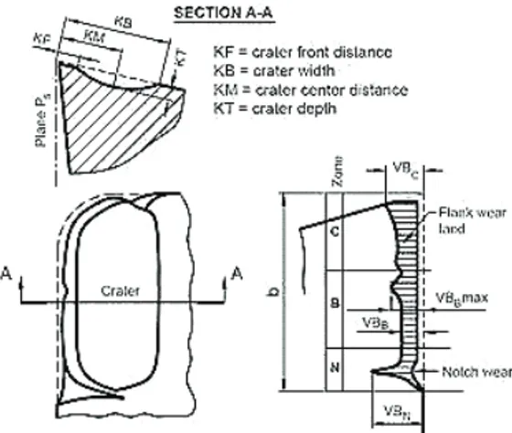
From the point of view of efficient nickel superalloy machining it was difficult to determine individual cutting tool wear mechanisms. These materials belong among difficult-to-machine materials that create articulated chip during machining, which results in the creation of large and highly dynamic cutting forces. High strength, mechanical hardening and adhesion result in notch shaped wear at the maximum cut depth level, while extremely abrasive environment is created for the cutting tool edge at the same time. Due to very low heat conductivity and high hardness of the machined material a large amount of heat was generated during machining, significant mechanical hardening was observed and the material stuck to the cutting edge easily and created a deposit there. [1, 2]
Figure 5 Tool wear according to ISO 3685:1993 [11]
The cutting tool wear was generated by exposing the edge to high mechanical and thermal loads and was characterized by creating a groove on the ridge at the place, where the tool was leaving the cut. This was caused primarily by the tool cutting edge going into stroke at a hardened layer of material, whose mechanical properties, especially hardness, are different from the basic material. The groove at the flank was generated by the process of sticking of machined material onto the cutting edge and following tearing out of the tool cutting material. This was accompanied by creation of burrs at this location.
This phenomenon is characteristic for machining of nickel alloys using low cutting speeds, where the machined material is pushed in front of the tool blade edge.
Wear of the tool cutting wedge: - Feed f = 0,3 mm, VBB = 0,3 mm
Figure 6 Insert - CNMG 120408 - TF (tAs = 8 min)
Figure 7 Insert - CNMG 12- SMR 0408 (tAs = 7,35 min)
Figure 8 Insert - CNMG 120408 - M5 (tAs=3,75 min)
- Feed f = 0,5 mm, VBB = 0,4 mm
Figure 9 Insert - CNMG 120408 - TF (tAs = 1,64 min)
Figure 11 Insert - CNMG 120408 - M5 (tAs = 1,22 min) 5 Processing and analysis of measured values
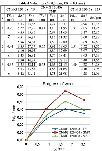
The measurement of flank wear of exchangeable cutting inserts was done by micrometric method by direct measurement of linear dimensions in individual sections to previously set wear value of VBB = 0,3 mm (feed 0,3
mm) and 0,4 mm (feed 0,5 mm). Determination of the roughness parameters Ra and Rz was done using the Surftest SJ - 210 roughness tester. Roughness was measured in longitudinal direction (parallel to movement direction) always in three places turned by 120°.
- Machined length Li = 50 mm
- Number of passes i = 5
- Previously set wear value VBB = 0,3 mm and 0,4 mm.
Table 3 Values for (f = 0,3 mm, VBB = 0,3 mm)
CNMG 120408 - TF CNMG 120408 - SMR CNMG 120408 - M5 i VBB mm μm Ra μm Rz VBmm B μm Ra μm Rz VBmm B μm Ra μm Rz 1 0,16 2,44 6,89 2,15 8,57 0,11 2,19 8,76 2,26 9,57 0,23 2,96 11,28 2,85 10,15 2,32 7,64 2,07 8,54 2,66 10,30 x 2,30 7,70 2,17 8,96 2,82 10,57 2 0,18 2,37 9,16 2,46 10,16 0,13 2,26 11,65 2,36 9,14 0,28 3,35 13,58 3,45 13,30 2,63 9,58 2,28 10,27 3,48 14,45 x 2,49 9,63 2,30 10,35 3,43 13,78 3 0,22 3,17 12,15 2,87 11,85 0,22 2,75 13,30 2,98 14,14 0,33 4,12 16,59 3,87 17,27 2,93 12,26 3,12 13,49 3,95 17,92 x 2,99 12,09 2,95 13,64 3,98 17,26 4 0,25 2,97 13,69 3,15 14,23 0,25 3,47 17,66 3,27 15,33 0,38 4,20 19,52 4,27 20,36 3,27 11,13 3,36 16,85 4,23 19,16 x 3,13 13,01 3,37 16,61 4,23 19,68 5 0,30 3,33 13,65 3,16 14,87 0,34 4,17 18,74 3,85 19,22 0,51 4,87 21,36 4,62 21,60 3,27 14,79 3,92 18,33 4,74 21,17 x 3,25 14,44 3,98 18,76 4,74 21,38
Figure 12 The process of insert wear (f = 0,3 mm, VBB = 0,3 mm)
Table 4 Values for (f = 0,5 mm, VBB = 0,4 mm)
CNMG 120408 - TF CNMG 120408 - SMR CNMG 120408 - M5 i VBB / mm] Ra / μm Rz / μm VBmm B / Ra / μm Rz / μm VBmm B / Ra / μm Rz / μm 1 0,28 4,33 15,66 5,27 17,25 0,41 3,27 10,37 3,15 11,95 0,32 2,98 11,36 2,85 13,26 4,85 15,90 2,97 11,65 3,17 12,26 x 4,81 16,27 3,13 11,32 3,00 12,29 2 0,41 5,96 24,63 6,85 27,37 0,65 3,58 17,89 3,92 19,65 0,51 3,69 16,53 3,52 18,55 6,16 26,95 3,80 17,69 3,67 17,50 x 6,33 26,32 3,76 18,41 3,63 17,53 3 0,35 8,70 34,27 8,25 32,14 0,53 4,76 23,14 4,65 21,15 0,40 4,40 23,66 4,28 21,28 8,33 33,87 4,83 21,65 4,16 23,95 x 8,42 33,42 4,75 21,98 4,28 22,96
Figure 13 The process of insert wear (f = 0,5 mm, VBB = 0,4 mm)
Maximum height of profile Rz [12]: μm 125 0 8 2 2 ε ε r f , r f Rz = ⋅ ⋅ =
(1)
Where: f – federate (mm), rɛ - nose radius (mm).
Arithmetical mean deviation of the assessed profile
Ra [12]:
( )
d μm 1 1 x x Z l Ra=∫
l (2) Where: l - evaluation length (mm), Z(x) - arithmetic mean of the absolute values (μm).Calculation of machine time tAs: min As fLn t i ⋅ = (3) Where: Li - machined length (mm), f - feedrate (mm), n -
revolutions (min−1).
Amount of cut-off material V:
3 3 As p c⋅ ⋅ ⋅ ⋅10 mm =v a f t V (4)
Where: vc - cutting speed (m/min), ap - depth of cut
(mm), f - feed per revolution (mm), tAs - machine time
(min).
Table 5 Evaluation of results (f = 0,3 mm, VBB = 0,3 mm) Exchangeable inserts tAs / min V / mm3 Ra / μm Rz / μm
CNMG 120408 - TF 8 300 000 3,25 14,40
CNMG 120416 - SMR 7,35 275 625 3,80 17,85 CNMG 120408 - M5 3,75 140 625 3,60 14,60
Figure 14 The value of surface roughness parameters Ra (f = 0,3 mm)
Figure 15 The value of surface roughness parameters Rz (f = 0,3 mm)
Table 6 Evaluation of results (f = 0,5 mm, VBB = 0,4 mm) Exchangeable inserts tAs / min V / mm3 Ra / μm Rz / μm CNMG 120408 - TF 1,64 102 500 6,30 25,60 CNMG 120416 - SMR 0,85 53 125 3,10 11,20 CNMG 120408 - M5 1,22 76 250 3,25 14,45
Figure 16 The value of surface roughness parameters Ra (f = 0,5 mm)
Figure 17 The value of surface roughness parameters Rz (f = 0,5 mm)
Figure 18 Machined part - material Ni-625 (Inconel 625) 6 Conclusion and direction of future research
The goal of this experimental activity was to analyse the status quo of the Inconel 625 nickel superalloy machining, experimentally verify and propose the way to easily and effectively machine these materials. For this we first need to design the tool, cutting material, cutting geometry and cutting conditions. Cutting inserts intended for machining nickel superalloys made from coated sintered carbide were used, and the cutting tool geometry was selected to resist mechanical and thermal stresses and vibrations during machining the best, which would positively influence the quality of machined surface.
Two feed rates were set in order to experimentally evaluate the influence of feed rate on durability and wear of exchangeable cutting inserts under given cutting conditions, namely f = 0,3 mm and 0,5 mm. The amount of cutting tool flank wear and achieved roughness of machined surface were used as evaluating criteria for machining the nickel superalloy. The amount of cutting blade edge wear and roughness of machined surface were monitored up to the set value of blade flank wear, namely
VBB = 0,3 mm for the feed of f = 0,3 mm, and VBB = 0,4
mm for the feed of f = 0,5 mm.
Machining results and suitability of use of individual exchangeable cutting inserts were influenced primarily by specific properties of machined material, tool cutting material and the type of coating. The measured values and graphs show progress of the tool wear, as commonly described in literature. The edge dulls quickly in the first phase, then in the second phase the tool machines without significant increase in wear, until it reaches the third phase with faster tool wear and loss of machining ability. The proposed feed of f = 0,5 mm caused that the tool started dulling faster, and in spite of the higher set wear value VBB = 0,4 mm, durability of the tool cutting edge
was lower. The cutting tool dulling was faster during the first and second phase of machining than in the first case (with the feed of f = 0,3 mm). All three exchangeable cutting inserts experienced lowering of toll flank wear values; it was primarily caused by creation of deposits and micro-welds on the cutting tool flank. Faster tool wear manifested itself also on roughness of the machined surface and primarily on lower work productivity.
This experiment was done with three different cutting inserts, each of them using a combination of two feeds. The achieved results show that the blade marked CNMG 120408 - TF from the IC 807 tool material was the most suitable for machining of the Inconel 625 superalloy.
Acknowledgements
The article has been done in connection with project Increasing of Professional Skills by Practical Acquirements and Knowledge, reg. no. CZ.1.07/2.4.00/17.0082 supported by Education for Competitiveness Operational Program financed by Structural Founds of Europe Union and from the means of state budget of the Czech Republic.
7 References
[1] Stahl, J-E. Metal cutting – Theories and models. Sweden: Division of Production and Materials Engineering. Lund University Sweden, 2012, 580 p. ISBN 978-91-637-1336-1. [2] Neslušan, M.; Czán, A. Obrábanie titánových a niklových zliatin. Žilina: Žilinská univerzita v Žilině / EDIS, 2001, 189 p. ISBN 80-7100-933-4.
[3] Maurotto, A. et al. Comparing machinability of Ti-15-3-3-3 and Ni-625 alloys in UAT. // 5th CIRP conference on High Performance Cutting, 2012, http://www.sciencedirect.com (Accessed 2013-10-01).
[4] Specialmetals.com. c2009. Machining Special Metals. http://www.specialmetals.com/documents/machining.pdf (Accessed 2013-10-01).
[5] Ezugwu, E. O. et al. The machinability of nickel-based alloys: a review. // Journal of Materials Processing Technology. 86, (1999), pp. 1-16. DOI: 10.1016/S0924-0136(98)00314-8
[6] Iscars Ltd. ISO Turn. http://www.iscar.com/Ecat/ familyhdr.asp?fnum=60&app=970&mapp=IS&GFSTYP= M&lang=EN&type=1 (Accessed 2013-10-02).
[7] Sandvik Coromant s.r.o. Soustružnické nástroje – Všeobecné soustružení. http://www.sandvik.coromant.com/ sitecollectiondocuments/downloads/global/catalogues/cs-cz/turn_a.pdf (Accessed 2013-10-02).
[8] Seco Tools s.r.o. Soustružení. http://www.secotools.com/ CorpWeb/Downloads/seconews2_2011/MN/turning/Turnin g%202012_CZ_LR.pdf (Accessed 2013-10-02).
[9] DMG/Mori Seiki. SL - 403.
http://www.dmgmoriseikiusa.com/sl-series/sl-403 (Accessed 2013-10-02)
[10]Sadilek, M.; Čep, R.; Sadílková, Z.; Valíček, J.; Petřkovská, L. Increasing tool life in turning with variable depth of cut. // Materiali in tehnologije/Materials and technology. 47, 2(2013), pp.199-203.
[11]ISO 3685:1993. Tool-life testing with single-point turning tools, Geneva, International Organization for Standardization, 48 p.
[12]ISO 4287:1998. Geometrical product specifications – Surface texture: Profile method – Terms, definitions and surface texture parameters.
Authors’ addresses
Jana Petrů, multi MSc., MA.Ph.D. VŠB - Technical University of Ostrava 17. listopadu 15/2172, 708 33 Ostrava - Poruba, Czech Republic
jana.petru@vsb.cz Tomáš Zlámal, MSc.
VŠB - Technical University of Ostrava 17. listopadu 15/2172, 708 33 Ostrava - Poruba, Czech Republic
tomas.zlamal@vsb.cz
Robert Čep, Assoc. Prof. MSc., Ph.D. VŠB - Technical University of Ostrava 17. listopadu 15/2172, 708 33 Ostrava - Poruba, Czech Republic
robert.cep@vsb.cz
Marek Sadílek, Assoc. Prof. MSc., Ph.D. VŠB - Technical University of Ostrava 17. listopadu 15/2172, 708 33 Ostrava - Poruba, Czech Republic
marek.sadilek@vsb.cz
Dana Stančeková, Assoc. Prof. MSc., PhD.
Faculty of Mechanical Engineering of University of Zilina Department of Machining and Manufacturing Technology Univerzitna 1, 010 26 Zilina, Slovak Republic
![Figure 1 Mori Seiki SL – 403[9]](https://thumb-ap.123doks.com/thumbv2/123dok/1333273.2513876/2.892.470.791.753.1046/figure-mori-seiki-sl.webp)