Taming Complexity in Large-Scale System Projects
Shimon Schocken
Efi Arazi School of Computer Science
IDC Herzliya
September, 2011
ABSTRACT
Engaging students in large system development projects is an important educational objective, since it exposes design and programming challenges that come to play only with scale. Alas, large scale system projects can be monstrously complex – to the extent of being infeasible in academic settings. We describe a set of principles and a framework that enable students to develop large-scale systems, e.g. a complete hardware platform or a compiler, in several semester weeks.
INTRODUCTION
As computers and networks become more complex and specialized, students increasingly lose sight of the big picture, failing to comprehend how hardware and software systems work together, as one enterprise. In order to address this problem, we developed a course [1] and a book [2] that provide a synthetic, hands-on view of applied computer science, as it unfolds in the process of building a
general-purpose computer system – hardware and software – in one semester. All the course materials, software tools and projects are available on the web, freely and in open source [3].
Our approach is based on a series of hands-on hardware and software construction projects, leading to the creation of a simple, yet surprisingly powerful, computer system. The hardware projects (building a CPU, RAM, and an overall computer platform called Hack) are implemented in a simple hardware description language. The software projects (building an assembler, virtual machine, and a compiler for a simple Java-like language called Jack) can be done in any programming language. Toward the course's end, the students use Jack to write a mini OS and develop some cool application, the popular choice being interactive computer games. This explains the "From Nand to Tetris" title under which the course is typically offered.
How can we squeeze so much work into a single one-semester course? This is the central question that the paper seeks to answer. We describe the various design techniques and pedagogical principles that we used to ease and streamline the students' workload in the course, as they build the computer from the ground up. Some of these techniques, and certainly all the principles, can inform the planning of any large-scale system project, in and out of academia. In particular, we describe four guiding design principles, and illustrate how they can be used to contain development complexity: modularity, abstraction, staging, and focus. We end the paper with general comments about designing and planning large-scale system projects in the context of CS education.
The paper includes many references to a web site [3] where readers can find and use all the software tools and project materials mentioned in the text.
MODULARITY
supplied in the course web site [3]. The exact contract for each chip development is as follows: "when loading your HDL implementation into the hardware simulator and testing it using the supplied test script, the simulator should generate the same outputs listed in the supplied compare file." The
simulator compares the actual and the desired outputs automatically, as a side-effect of evaluating the chip's logic.
Altogether, the Hack hardware platform comprises 33 chips. The chips are constructed gradually, and bottom up, starting with elementary Nand.hdl chips and ending a few weeks later with the final Computer.hdl chip. Let us describe the first few rungs in this construction. Using a given Nand gate (the only "given" artifact in the course), the student is guided to build a Not gate; using Not and Nand gates, an And gate is built; using Not and And gates, an Or gate is built; using Or, And, and Not gates, a Multiplexor is built, and so on. At the end of this recursive ascent – divided into five projects and five semester weeks – a simple Von Neumann platform emerges. This platform is called Hack.
Special care and several design iterations were needed to turn Hack into a highly modular and succinct architecture. As a result, each chip in the architecture consists of just a few lower-level chip parts, and, correspondingly, can be implemented with just a few lines of HDL code. The most complex chip – the CPU – can be implemented with 17 lines of HDL code. The top-most chip – the Computer itself – is implemented with three lines of code, specifying the connectivity of the three lower-level chips of which it is made: CPU, RAM, and ROM.
Students routinely build this hardware platform in five semester weeks. Next, they move on to build the computer's software hierarchy, whose development is broken into seven projects. Each software project is specified by an API describing several classes, each consisting of a handful of methods (most students implement our API's using Java, C#, Python, and Perl). For example, the Assembler API includes a Parser class (8 methods), a CodeGenerator class (3 methods), and a SymbolTable class (4 methods). As with the hardware projects, the students are not told "go build an assembler." Rather, they are given a detailed blueprint and a plan of action that walks them through a staged development of each API, from simple to complex methods. In each step, they are guided to unit-test their work with supplied test files.
To summarize, the course atoms are chips and methods. The course web site provides a complete description and specification of each atom, in the form of API's and test scripts; the student's task is to follow proposed implementation plans and build and integrate these atoms into a full-blown computer system. Note that the students are not engaged in any design tasks, as all the chip and class API's are given, along with the necessary unit-testing files. Working from given design documents is extremely important on pedagogical grounds, as we argue later in the paper.
The course normally engages students who took only introductory CS courses. That students with limited programming experience and no hardware background can build this computer in one semester is a triumph of modular design and unit-testing. Equally important is an abstract view of the task at hand, as we now turn to explore.
ABSTRACTION
We believe that abstraction holds the key to containing complexity. With that in mind, we view a computer system as a set of abstractions [4]. A module's abstraction specifies precisely and
The bonds that enable abstractions to interact with each other and with external test programs are agreed-upon input and output argument names. Thus, these names must also be part of the abstraction's specification. The separation of abstraction (the "what") from implementation (the "how") is of course a hallmark of sound system design [5,6]. Our course illustrates the benefits of this principle in a vivid and hands on fashion. Let us give an example, taken from the domain of hardware design. We begin with a brief overview of how the hardware simulator works.
Consider the 16-bit adder implementation shown in Figure 1b. To test this adder, one loads the file Add16.hdl into the hardware simulator. The simulator then starts parsing the loaded HDL code. When the simulator encounters the name of a lower-level chip part, say FullAdder, it searches the user's directory for a file named FullAdder.hdl. If such a file is found, the simulator recurses to parse its HDL code, all the way down to the Nand gates level. Once the entire parse tree is thus constructed, the simulator begins evaluating the chip logic. This is done either interactively, using test values supplied by the user via the simulator's GUI, or batch-style, by reading test values from a supplied test script. In either case, the simulator binds the chip's input variables to the test values and percolates the results through the parse tree, all the way up to the chip's output variables.
A few years ago, when we implemented the hardware simulator in Java and prepared the hardware projects, we observed that each chip abstraction (e.g. FullAdder) can be implemented in at least two different ways: as an HDL program, stored in, say, a FullAdder.hdl file, and also as a Java class, stored in a FullAdder.java file. Both implementations realize – albeit in remarkably different ways – the same abstraction, delivering precisely the same chip functionality. Exploiting this duality, we've augmented the hardware simulator with a library of 33 Java classes, each implementing the specified function of one member of the Hack chip set. This was done in order to speed up the simulator's operation and compensate for missing chip parts.
Here is an example of how this dual functionality comes to play: suppose we use the hardware simulator to evaluate the Add16.hdl chip implementation shown in Figure 1b, consisting of 16 inter-connected and lower-level FullAdder chip parts. What should the simulator do if, in the course of this top-down
evaluation process, it fails to find the corresponding FullAdder.hdl file in the user's directory? The simplest solution would have been to halt with an "unknown chip part: FullAdder" exception. Yet our simulator is more forgiving: when it fails to find FullAdder.hdl in the user's directory, it automatically reverts to using the services of its built-in FullAdder.java file, without forestalling the evaluation of the parent chip. In general, the functionality of any missing X.hdl file is automatically delivered by a corresponding X.java class, if such is available in the simulator's built-in chips library.
This convention had far-reaching implications on the course delivery. Although the standard course entails building the entire hardware platform from the ground up, the built-in "java chips" enable the freedom of building this platform in any desired scope and order. Operationally, HDL code written by students may well include missing chip part implementations, either because the instructor decided to exclude them from the project or because the student had trouble implementing them. This void will have no impact on simulating and testing the parent chip: built-in Java chips will automatically kick in to stand for any missing parts in the implementation. In fact, when developing any given chip in the context of some hardware projects, it makes sense to intentionally ignore HDL implementations of requisite lower-level chips developed in previous projects. This way, the student is assured to use proven built-in Java chips, without having to worry about old bugs creeping into the current work.
We note in passing that the hardware simulator is completely independent of the Hack platform. Different people can design and simulate different hardware platforms and chip sets, as needed. Further, if they wish to run behavioral simulation of their platforms and test their design before they set out to implement them in HDL – either partially or completely – they can write their own library of built-in Java chips, and add the library to the simulator's environment. The simulator's software is open source, and is specifically built to support the design and implementation of different hardware
CHIP Add16 {
IN a[16], b[16]; // 16-bit inputs OUT out[16]; // 16-bit sum a + b
// Computes the 16-bit sum a + b according to the rules of // binary addition. The most significant carry bit is ignored. }
Figure 1a: Typical HDL "stub file", specifying a 16-bit adder abstraction.
CHIP Add16 {
IN a[16], b[16]; // 16-bit inputs OUT out[16]; // 16-bit sum of a + b
// Computes the 16-bit sum a + b according to the rules of // binary addition. The most significant carry bit is ignored. PARTS:
FullAdder (a = a[0], b = b[0], c = 0, sum = out[1], carry = c0); FullAdder (a = a[1], b = b[1], c = c0, sum = out[1], carry = c1); FullAdder (a = a[2], b = b[2], c = c1, sum = out[2], carry = c2); . . .
FullAdder (a = a[15], b = b[15], c = c14, sum = out[15]); }
Figure 1b. Implementation of the chip abstraction from Figure 1a: this classic design is based on 16 "full-adders" (Fig. 1c below), each contributing one bit to the sum and propagating its carry bit to the next adder (the least significant carry bit is set to 0; the most significant carry bit is ignored). Note that each HDL line describes a lower-level chip part, along with its connections to other chip parts. Inter-chip connections (e.g. c0, c1, c2, …) are declared as needed.
CHIP FullAdder {
IN a, b, c; // 1-bit inputs
OUT sum, carry; // 1-bit outputs: right bit of a + b + c and the carry bit PARTS:
HalfAdder (a = a, b = b, sum = sum1, carry = carry1); HalfAdder (a = c, b = sum1, sum = sum, carry = carry2); HalfAdder (a = carry1, b = carry2, sum = carry);
}
CHIP HalfAdder {
IN a, b; // 1-bit inputs
OUT sum, carry; // 1-bit outputs: right bit of a + b and the carry bit PARTS:
Xor (a = a, b = b, out = sum); And (a = a, b = b, out = carry); }
Figure 1c. Possible implementations of the chip parts from Figure 1b; Each chip is made of lower-level chips, all the way down to Nand gates (not shown here)
STAGING
In and by itself, a modular design is a static artifact; it is not a plan of action. In order to turn the design into an executable artifact, an implementation plan must be articulated. We believe that seeing such plans, and understating their pros and cons by actually following them, is an important part of computer science education.
Good implementation plans are typically staged. The general staging strategy is based on
decomposition: when seeking a solution S to a given problem P, it is usually better to start by solving a reduced problem P', and then extending its solution S' into the final solution S. In some cases, the reduction from P to P' is straightforward, and so is the extension of S' to S. In other cases, the stages must be contrived with care and foresight. We now give two examples of this strategy, as they come to play in the course.
The first example is the development of an assembler for the Hack assembly language [2]. The implementation plan is three-staged, as follows. First, the students are guided to develop a basic assembler (S') that can handle programs without labels (P'). This is a fairly straightforward task – one simply translates symbolic mnemonics into their binary equivalents, using the machine language specification. Next, the students are walked through the implementation of an API designed to build and use a symbol table. Finally, and using this added functionality, the students extend their basic assembler into a final assembler (S) capable of handling any assembly program, with or without symbols (P).
In this case, the P P' reduction and the S' S extension are relatively straightforward. And yet even here, as always, the architect must exercise care and foresight. First, the API of the basic solution must be planned from the outset in a manner that facilitates a smooth transition to the final solution; ideally, the basic API of S' should become a subset of the final API of S. Second, the separation to stages must be supported by test files (e.g. assembly programs with and without symbols) and by a staged unit-testing plan. All these elements must be put in place by the system architect before development ensues.
The second example is the development of a compiler for Jack, the high-level language of the Hack/Jack platform. Jack is an object-based language with a Java-like syntax. Following the Java/C# paradigm, Jack code is compiled into an interim VM language, designed to operate on a stack-based virtual machine. There are two alternatives for executing the resulting VM programs. One can either execute them directly, using a supplied VM simulator available in the course web site [3], or one can translate them further, into native Hack code, and then run the resulting binary code on the Hack computer built previously. Our VM model and simulator are described in detail in [7].
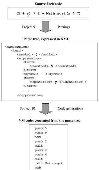
This two-tiered compilation scheme implies a two-tiered compiler: from Jack to the interim VM language, and then from the VM language to assembly. The development of this compiler is broken into four separate projects and four semester weeks. Let us focus on the top tier of the compiler (sometimes called front-end), whose operation is illustrated in Figure 2. This tier is designed to translate source Jack code into target VM code. The translation task consists of two main sub-tasks: parsing the source code into some canonic representation, and then generating target code from the representation. Note that parsing depends only on the grammar of the source language, while code generation depends only on the grammar of the target language.
Source Jack code
(5 + y) * 2 – Math.sqrt(x * 7)
Project 9 (Parsing)
Parse tree, expressed in XML
<expression> <term>
<symbol> ( </symbol> <expression>
<term>
<constant> 5 </constant> </term>
<symbol> + </symbol> <term>
<identifier> y </identifier > </term>
. . .
</expression>
Project 10 (Code generation)
VM code, generated from the parse tree
push 5 push y add push 2 mult push x push 4 mult
call Math.sqrt sub
Figure 2. High-level Jack code (top) is compiled into VM code (bottom).
The XML code in the middle is an intermediate artifact, designed to decouple the translator's development into two separate and stand-alone projects.
The next project guides the students through the process of converting the XML representation into a stream of VM commands. This is done by an algorithm that performs a depth-first traversal of the XML code, generating VM commands on the fly (note that the XML file is essentially a parse tree, slanted horizontally). For example, when reaching a terminal XML node of the form <constant> 5 </constant>, the algorithm outputs "push 5"; when backtracking into an interim node of the form <symbol> + </symbol>, the algorithm outputs "add", and so on. This process emits a VM program,
as seen in the bottom of Figure 2. The VM program can then be loaded and executed on the VM simulator, or translated further into assembly (the latter translation is carried out by the compiler's "back-end", whose development entails two additional projects, not described here).
To summarize the development of the compiler's front-end, one project deals with translating a Jack program into XML; the subsequent project deals with translating the XML into executable VM code. At this point, though, the XML scaffolding has served its purpose, and can be removed from the scene. Thus, in the last part of the project, the students modify the compilation engine developed in the previous project, replacing the logic that generated static XML code with logic that generates
executable VM code. Thus, the design of the basic compiler is essentially morphed into the design of the final compiler.
At the end, of course, a compiler is a compiler is a compiler. All the effort described in this section – staging, unit-testing, XML representation, morphing – is invested in order to tame the development's complexity and ration the student's workload into a manageable series of homework assignments. Needles to say, there is an important lesson here: modular and staged design also promotes the development of high quality software [5], and a carefully planned set of homework assignments is quite similar to a well-planned set of programming sub-tasks.
FOCUS
Constructing a general-purpose computer from first principles is a humongous undertaking;
accomplishing this task in one semester requires some concessions. With that in mind, our approach is based on four simplifying principles: no exceptions, no efficiency, no special features, no design uncertainty.
No exceptions: throughout the projects, it is deliberately and explicitly assumed that all inputs are error-free. For example, when writing the assembler or the compiler, we assume that the source files that the translators have to process contain only valid Hack and Jack code, respectively; there is no need to write error checking and messaging code. In a similar fashion, when we develop the Add16 chip or the ALU, we explicitly ignore overflow; there is no need to design special logic and circuitry to handle this exception.
We believe that ignoring exceptions – if done openly and explicitly – is perfectly acceptable. The act of analyzing and documenting missing or wanting features in one's implementation is an important exercise, educating for honesty and precision.
No efficiency: Some of our hardware and software designs are inefficient. For example, consider how we build a RAM chip. First, we build an 8-register RAM. Next, we assemble eight such chips with direct addressing logic to build a 64-register RAM. Next, we assemble eight such chips to build a 512-register RAM. Three similar steps later we end up with the 16K memory chip required for the Hack computer. The resulting RAM design is elegant, but far from optimized. In the context of this course though, this is acceptable: striving for elegance is no less important than striving for efficiency, and in most cases both pursuits lead to the same end.
Invaders were already developed in the Jack language by students and self-learners. Following compilation, these programs run smoothly on the Hack platform (for example, see [8]).
No special features: It would be nice to have a fancy ALU that supports floating point arithmetic; it would be nice if the high level language featured more data types; it would be nice if the compiler had error diagnostics; it would be nice if the virtual machine were optimized; it would be nice is the operating system supported a file system; it would be nice to write a Scheme interpreter over the Hack platform; it would be nice to write a C compiler; and wouldn’t it be nice if two Hack machines could communicate over the Internet? The list of "nice to haves" goes on and on. Every one of these suggestions provides an excellent pretext for a fruitful and lively class discussion and advanced projects.
No design uncertainty: In this course, all the software designs are given. The students are not asked to design anything – they "merely" have to implement the supplied HDL stub files and APIs. We believe that except for software design courses, students should not be asked to design systems. Our experience shows that college students, as well as entry-level programmers, are not sufficiently mature to engage in design; letting them loose on a non-trivial design task can cause more damage than benefit. License to design a system should be given only after one has reviewed, understood, and implemented, many examples of good designs. Thus, discussing and implementing good designs – either by creating or borrowing them – should be a central part of our teaching mission.
Taken together, the limited treatment of exceptions, efficiency, and special features serves an
important educational purpose: it focuses the students' minds on the big picture. One of the major goals in this course is to expose great ideas and gems in applied computer science, as they unfold in hands-on implementatihands-ons. This level of engagement requires focus and chands-oncentratihands-on that cannot be achieved without setting explicit limits on scope and resolution.
DISCUSSION
Since we've made the course materials freely available on the web, thousands of students from India, China, Africa, and western countries have built the Hack/Jack computer system. This learning experience took place in traditional academic settings as well as in self-organized study groups, ranging from Harvard University to the University of the People. The vast majority of the students who complete this course know nothing about hardware or compilation upon starting their journey. And yet many of them are happy campers, expressing publicly the joy and satisfaction they experience building the machine.
In addition to regular students, the course is taken by many self-learners, having nothing but intellectual curiosity and pursuit of knowledge to motivate their work (for a typical self-organized course site using our course materials, see [9]). This, for us, is indirect evidence that complexity has been tamed, or at least contained. This could not have been accomplished without the four critical success factors described in this paper: modularity, abstraction, staging, and focus. It's important to note that none of these elements is a natural or obvious feature of the system that one seeks to develop. Rather, they must be contrived and articulated by the system architect [10].
In our case, and in the case of many readers of this article, the architect is also the course instructor, toiling to prepare his or her course materials. Too often, we spend huge amounts of time on polishing our lectures, rather than on creating innovative projects and challenging problem sets. We believe that in computer science, the balance should be reversed: learning and competence are internalized by doing, not by attending lectures.
statement is a little more than "Here is a story about an airline reservation system. Now go build it." Such project preparation is not only unfair to the students, it may well turn them into sloppy engineers.
We believe that good engineering is good education [11]. We hope that our course provides a step in that direction.
Acknowledgement: I am indebted to Noam Nisan, whose brilliance and mastery of computer science made all this possible, and to Mark Armbrust, who manages the course's Questions and Answers forum with a unique balance of rigor and generosity. I am also grateful to our former students Yaron Ukrainitz and Yannai Gonczarowski, programming wizards and chief developers of the TECS software suite.
REFERENCES
[1] Schocken, S., Nisan, N. Armoni, M. 2009. A Synthesis Course in Hardware Architecture, Compilers, and Software Engineering, SIGCSE 2009 Proceedings.
[2] Nisan, N., Schocken, S. 2005. The Elements of Computing Systems. Cambridge, MA: MIT Press.
[3] Nisan, N., Schocken, S. 2005. TECS Course Web Site. www.idc.ac.il/tecs
[4] Kramer, J. 2007. Is abstraction the key to computing?, Communications of the ACM, Vol. 50, No. 4, pp. 37-42.
[5] Meyer, B. 2000. Object-Oriented Software Construction, Prentice-Hall.
[6] Hazzan, O. and Tomayko, J. 2005. Reflection and Abstraction Processes in the Learning of the Human Aspects of Software Engineering, IEEE Computer 38(6), pp. 39-45.
[7] Schocken, S. 2009. Virtual machines: abstraction and implementation, ITiCSE 2009 Proceedings.
[8] Tetris game example on the Jack/Hack Platform: http://tinyurl.com/4yxmoyv
[9] A do-it-yourself CS course, based on [3], administered by Parag Shah: http://tinyurl.com/3jotumk
[10] Parnas, D.L. 1972. On the criteria to be used in decomposing systems into modules. Communications of the ACM, Vol. 15 Issue 12, Dec. 1972.