TeknikA
67
A NEW METHOD TO SEPARATE RESISTIVE LEAKAGE
CURRENT OF ZnO SURGE ARRESTER
Novizon
1, Zulkurnain Abdul Malek
2,Aulia
3ABSTRACT
Increasing resistive leakage current is high responsible to the degradation of zinc oxide surge arrester. This current is temperature dependence which means the leakage current increase while the temperature of the zinc oxide increased. The resistive leakage current is part of the total leakage of ZnO arrester, means that total leakage current consist of resistive leakage current and capacitive leakage current. This current can obtain from the total leakage current of zinc oxide arrester by subtracting the capacitive current from the total leakage current. Currently, the most methods to separate the resistive leakage current require voltage measurement. Although, the result are satisfactions but still complicated and expensive caused by high voltage measurement needed. This paper develops a simple but accurate method to separating the resistive leakage current from the total leakage current. In this method did not require the voltage measurement so make it cheap to apply in device. The method based on the cancellation of capacitive leakage current from the total leakage current. To obtain capacitive leakage current some steps should be done and the results meet satisfaction.
I. INTRODUCTION
The excellent voltage-current nonlinear characteristic of zinc oxide surge arresters has been successfully utilized to eliminate series gap in metal surge arresters with silicon carbide nonlinear resistors. However, in long time application under the normal operating voltage stress, the leakage current of ZnO arrester increase and might occur thermal runaway then became the serious problem for power system.
Also, zinc oxide surge arresters should behave as an insulator at normal line to earth voltage. They have very high impedance resulting in leakage current with peak value of only a few mille amperes. During over voltage events the metal oxide surge arrester limits the voltage to an almost constant value, even if the discharge current increases extremely. This capability has been found to remain unchanged during its full life, but the insulation performance at operation voltage may subject to change [1]. However, under extreme condition this might lead to an increase of the leakage current. This change called degradation of metal oxide surge arrester. The third harmonic of the resistive leakage current is responsible to the degradation of ZnO surge arrester.
Several methods of separating the resistive leakage current from the total leakage current of ZnO surge arrester have been presented in the past. This paper reviews some methods and proposed a new method to separate resistive leakage current from total leakage current.
II. METHOD TO SEPARATE RESISTIVE
LEAKAGE CURRENT, REVIEW
A.Compensation Method [2]
Compensation method is the conventional monitoring method for separate resistive leakage
current ZnO surge arrester. It measuring principle is based on the orthogonally between the resistive leakage current and the capacitive leakage current. It satisfied the following equations:
I I I (1)
If the applied voltage is a pure sine wave, the capacitive current component can be written as shown in 2.
sh
c
Gv
i
(2)
Where
v
sh is the applied voltage, phase shiftedforward by 900 and G=ωCp. The resistive current is
in phase with the voltage and the capacitive component is orthogonal to the voltage. Therefore, these currents satisfy,
∫
πω
= Combining equation 1, 2 and 3,
with G is the amplifier gain. So the capacitive component of the leakage current is set completely to get the resistive component.
Compensation method was applied to leakage current measuring apparatus “LCD-4” type made in Japan, which monitors the total leakage current, the resistive leakage current and power loss.
Although compensation method was applied in the device, but applied condition of the device is limited; the influences of voltage harmonic and the hysteresis phenomenon in the dynamic v-i characteristic of ZnO surge arrester are negligible.
TeknikA
68
method concentrated to the elimination of the voltage harmonic influences. The monitoring results by variable coefficient compensation method [3] are satisfactory. Also, by multi coefficient compensation method [4] the capacitive current component is removed completely from the total leakage current. For the capacitive current compensation method [5] provided a new tool for monitoring ZnO surge arrester. All these methods requires voltage measurement in term to obtain the resistive leakage current.
B.Point of Wave Technique
A point of wave (POW) technique proposed by [6] suitable for on line condition monitoring of ZnO surge arrester. This technique does not rely upon harmonic analysis of the leakage current to obtain the resistive current. One cycle of the resistive current is determined by analysis of the voltage and leakage current wave shapes. The leakage current in the POW technique can be written as
I t I t I t C V I t (5)
Where Ic and Ir are the capacitive and resistive components of the leakage current respectively. Within each half cycle, a voltage level will occur twice except the voltage peak. Examining the leakage current wave shape at the times t1 and t2 when the voltage is equal in magnitude and polarity gives
I t I t I t C V I t
(6)
I t I t I t C V I t (7)
Since V(t1) = V(t2) we have Ir(t1)=Ir(t2). Subtracting Equation (3) from equation(2) can obtain
C dV tI t I t
dt dV tdt
8
Combining (6) with (7) and (8) gives
I t I t
Within the voltage half cycle, at the voltage level V(t1) and V(t2) where V(t1) =V(t2), the voltage derives are equal in magnitude but of opposite in polarity which gives
dV t dt
dV t dt Simplification of equation (9) to
I t I t I t I t
Although, the result of this technique meet satisfaction expected, but this technique still requires voltage measurement.
C.Compensation Circuit Technique [7]
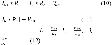
Figure-1shows the measurement circuit diagram used to separate the resistive leakage current and capacitive current from total leakage current flowing through ZnO blocks under power frequency ac applied voltage. In figure 1C1is reference capacitor, R1 is the variable resistor, and R2 is the fix resistor. The potential difference between b and a points is expressed as
If Xc1, which is the reference capacitive reactance in the component circuit, is much greater than R1, the Ic1 is assumed as a pure capacitive current. When the capacitive current passing through ZnO blocks is compensated by reference capacitive current, the equation are as follows.
TeknikA
69
III. MODIFIED TIME SHIFTED METHOD
(MTSM) PRINCIPLE
The MO surge arrester could be represented as a simplified equivalent circuit model comprised of a capacitance branch in parallel with a non-linear resistive branch as shown in fig. 2.
Figure-2 Simplified Model Representation of MO Surge Arrester.
The total leakage current (Ix) of the arrester is given by a vector sum of a capacitive component (Ic)with does not vary with degradation of the arrester and the resistive leakage current component (Ir) which varies with the degradation of the MO surge arrester as shown figure 3.
Figure-3 Vector Diagram of Ix, Ic and Ir All the current are time dependent, so the Ix, Ic and Ir can write as follow:
(14)
(15)
The resistive leakage current component could obtain with canceled the capacitor leakage current component from the total leakage current. The cancellation of capacitive leakage current component from total leakage current done by
adding another capacitive current Ic with different
phase angle π, so
(16)
cos
(17)
cos
(18)
. cos (19)
. cos
And [IR] is a resistive leakage current including harmonics.
A. The Modified Time Shifted Method Algorithm
The algorithm for calculating resistive leakage current using modified time shifted method can describe as follow :
(a) get reference of zero time of the total leakage current. (b) determine the frequency of the total leakage current. (c) add total leakage current with the its delay current as a quarter of period. (d) peak time the summation leakage current is the time correspond to the peak time of the resistive current. (e) a quarter of period of the peak time summation leakage current is the peak time of the capacitive leakage current. (f) generate capacitive leakage current based on frequency detected. (f) the resistive leakage current can obtain with subtracted capacitive leakage current from the total leakage current. Block diagram for the algorithm shows in figure- 4.
Figure-4 Block diagram of algorithm for calculating resistive leakage current using Modified Time
Shifted Method.
The algorithm has been simulated using MATLAB 7.0.1 and the result meet satisfactions.
TeknikA
70
Figure-6 TSM to obtain Ir
Figure-5, shows the simulation waveform for resistive current, capacitive current and total leakage current respectively. The resistive current peak is about 30mA and the capacitive current peak is about 10 mA. The peak current of total leakage current is 30 mA.
Simulation is running in Matlab software to obtain the resistive leakage current using MTSM and the result meet the satisfaction as shown in fig.6.
IV. MEASUREMENT SET UP
The modified time shifted method was developed as computer program put in PC to display the resistive leakage current result. For current measurement was used resistive divider with ratio 1 : 2000 and capacitive divider with ratio 1 : 686 for voltage measurement. In this case the voltage measurement just for validated the resistive leakage current result that is the same phase with the voltage. Both leakage current and voltage input were captured by digital oscilloscope Tektronix TDS3025 and input to PC for data acquisition as shown in Figure-4.
Figure-7 Experiment Set Up of the Leakage Current Measurement using Time Shifted Method
Series of experiments were carried on aged MO arrester taken from local electrical company (TNB). The specification and electrical properties of the sample arresters were used in this work are tabulated in table 1.
Table-1 Arrester Data
Manufacture : Ohio Brass, USA
Rated voltage : 12 kV
Rated current : 5 kA
Housing : Polymeric
V.RESULT
The measurements were performed on the age MO arresters at room temperature. The total leakage current and the voltage input were measured at the same time. The total leakage which measured by digital oscilloscope was calculated by computer based program for determination of the resistive leakage current. The resistive leakage current result for arrester sample 1 and 2 can be shown in figure 5 and 6.
Figure-8 Leakage Current Measurement, Modified Time Shifted Method, Resistive
Leakage Current.
Figure-9 Comparison the Result of MTSM and Compensation Method
VI.CONCLUSIONS
Some of the methods to separate the resistive leakage current were reviewed and all of the method require voltage measurement in term to obtain the resistive leakage current.
The new method based on the cancellation capacitive leakage current component from total leakage current has been done and the method did not require the voltage measurement.
The results of the new method more accurate compare with the compensation method that widely using currently.
0 0.005 0.01 0.015 0.02 0.025 0.03 0.035 0.04 -1
0 0.005 0.01 0.015 0.02 0.025 0.03 0.035 0.04 -1
TeknikA
71
REFERENCES
[1].Christian, H. et al,” Diagnostics and Monitoring
of Metal-Oxide Surge Arrester in High- Voltage Networks-Comparison of Existing and Newly Developed Procedures “, IEEE Trans.on Power Delivery Vol.16, No. 1, Jan. 2001
[2].J.Lundquist, et al, “ New Method For
Measurement Of The Resistive Leakage Current Of Metal-Oxide Surge Arrester In Service”, IEEE Trans. On Power Delivery, Vol.4,No.4, November 1990.
[3].Zhou Long et al,” A Study on Variable
Coefficient Compensation Method and Performance Diagnosis of Metal Oxide Arrester’s Operating State Detection”, Electric Technology Transaction, vol 13. No.6, Dec 1998.
[4].Tang Ju et al,” Study of Multi-Coefficient
Compensation Method on Resistive Current Passing Trough MOA”, High Voltage Engineering, Vol.25. No1 Mar.1999.
[5].Hanxin Zhu et al,” Influence of Harmonics in
System Voltage on Metal Oxide Surge Arrester Diagnostics,” IEEE Conference on Electrical Insulation and Dielectric Phenomenon, Austin, Oct 1999.
[6].C.A. Spellman et al,” A Technique for On-Line
Monitoring of ZnO Surge Arrester”, 10th International Symposium on High Voltage Engineering, Canada, August, 1997.
[7].Bok-Hee Lee et al,” A Monitoring Device of