The All-New
Switch Book
The Complete Guide to LAN
Switching Technology
Second Edition
Rich Seifert
Jim Edwards
The All-New
Switch Book
The Complete Guide to LAN
Switching Technology
Second Edition
Rich Seifert
Jim Edwards
Published by
Wiley Publishing, Inc. 10475 Crosspoint Boulevard Indianapolis, IN 46256 www.wiley.com
Copyright2008 by Rich Seifert and Jim Edwards Published by Wiley Publishing, Inc., Indianapolis, Indiana Published simultaneously in Canada
ISBN: 978-0-470-28715-6
Manufactured in the United States of America 10 9 8 7 6 5 4 3 2 1
No part of this publication may be reproduced, stored in a retrieval system or transmitted in any form or by any means, electronic, mechanical, photocopying, recording, scanning or otherwise, except as permitted under Sections 107 or 108 of the 1976 United States Copyright Act, without either the prior written permission of the Publisher, or authorization through payment of the appropriate per-copy fee to the Copyright Clearance Center, 222 Rosewood Drive, Danvers, MA 01923, (978) 750-8400, fax (978) 646-8600. Requests to the Publisher for permission should be addressed to the Legal Department, Wiley Publishing, Inc., 10475 Crosspoint Blvd., Indianapolis, IN 46256, (317) 572-3447, fax (317) 572-4355, or online at http://www.wiley.com/go/permissions.
Limit of Liability/Disclaimer of Warranty:The publisher and the author make no repre-sentations or warranties with respect to the accuracy or completeness of the contents of this work and specifically disclaim all warranties, including without limitation warranties of fitness for a particular purpose. No warranty may be created or extended by sales or promotional materials. The advice and strategies contained herein may not be suitable for every situation. This work is sold with the understanding that the publisher is not engaged in rendering legal, accounting, or other professional services. If professional assistance is required, the services of a competent professional person should be sought. Neither the publisher nor the author shall be liable for damages arising herefrom. The fact that an organization or Website is referred to in this work as a citation and/or a potential source of further information does not mean that the author or the publisher endorses the informa-tion the organizainforma-tion or Website may provide or recommendainforma-tions it may make. Further, readers should be aware that Internet Websites listed in this work may have changed or disappeared between when this work was written and when it is read.
For general information on our other products and services or to obtain technical support, please contact our Customer Care Department within the U.S. at (800) 762-2974, outside the U.S. at (317) 572-3993 or fax (317) 572-4002.
Library of Congress Cataloging-in-Publication Data is available from the publisher. Trademarks:Wiley, the Wiley logo, and are trademarks or registered trademarks of John Wiley & Sons, Inc. and/or its affiliates in the United States and other countries, and may not be used without written permission. All other trademarks are the property of their respective owners. Wiley Publishing, Inc., is not associated with any product or vendor mentioned in this book.
happiness that life has to offer. I am looking forward to all of the things that she will be teaching me for the many years to come.
Credits
Executive Editor
Carol Long
Senior Development Editor
Tom Dinse
Production Editor
Rachel McConlogue
Copy Editor
Nancy Rapoport
Editorial Manager
Mary Beth Wakefield
Production Manager
Tim Tate
Vice President and Executive Group Publisher
Richard Swadley
Vice President and Executive Publisher
Joseph B. Wikert
Project Coordinator, Cover
Lynsey Stanford
Proofreader
PubServices
Indexer
Jack Lewis
Cover Image
Jupiter Images
Contents
Preface xxiii
Introduction xxv
Part One Foundations of LAN Switches
Chapter 1 Laying the Foundation 3
Network Architecture 4
Physical Layer 5
Data Link Layer 6
Network Layer 7
Transport Layer 7
Session Layer 8
Presentation Layer 8
Application Layer 9
Layering Makes a Good Servant but a Bad Master 9
Inside the Data Link Layer 12
Modes of Operation 12
Data Link Sublayering 15
Logical Link Control 16
Addressing 19
Local and Global Uniqueness 19
LAN Data Link Addresses 20
Unicast and Multicast Addresses 21
Globally Unique and Locally Unique MAC Addresses 23
How LAN Addresses Are Assigned 24
Written Address Conventions 26
LAN Technology Review 27
Ethernet 27
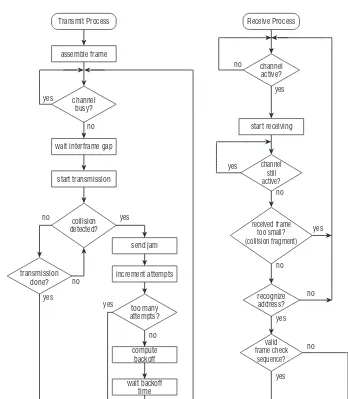
Ethernet Medium Access Control 28
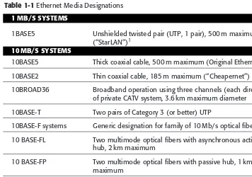
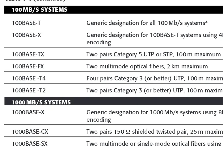
Ethernet Physical Layer Options and Nomenclature 31
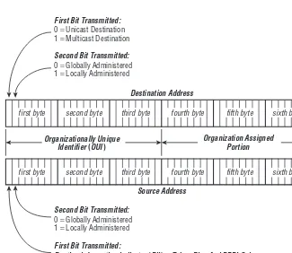
Ethernet Frame Formats 33
Bit-Ordering 38
Token Ring 38
Token Ring Medium Access Control 39
Token Ring Physical Layer Options 41
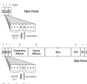
Token Ring Frame Formats 41
Bit-Ordering on Token Ring LANs 43
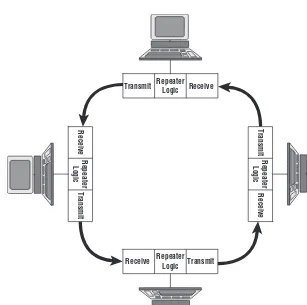
Fiber Distributed Data Interface 43
FDDI Operation 43
FDDI Physical Signaling 45
FDDI Frame Format 45
Other LAN Technologies 46
IEEE LAN Standards 48
IEEE 802 Organization 49
IEEE 802 Naming Conventions, or ’’Mind Your Ps and Qs’’ 50
IEEE 802.1 51
IEEE 802.3 53
IEEE 802.5 54
Other Standards Organizations 54
Terminology 55
Applications, Clients, and Service Providers 56
Encapsulation 57
Stations and Interconnections 59
Chapter 2 Transparent Bridges 63
Principles of Operation 63
Unicast Operation 65
Unknown and Multicast Destinations 66
Generating the Address Table 68
Address Table Aging 69
Process Model of Table Operation 70
Custom Filtering and Forwarding 72
Multiple Bridge Topologies 73
Transparent Bridge Architecture 74
Maintaining the Link Invariants 76
The Hard Invariants Are Hard Indeed 78
Soft Invariants 80
Implementing the Bridge Address Table 84
Table Operations 85
Search Algorithms 85
Hash Tables 85
Binary Search 88
Content-Addressable Memories 90
How Deep Is Your Table? 92
Bridge Performance 95
What Does It Take to Be the Best? 95
If You’re Not the Best, How Good Are You? 97
The IEEE 802.1D Standard 98
Operating Parameters and Requirements 99
Aging Time 99
Bridge Transit Delay 99
Additional Operating Requirements 101
Bridge Address Assignment 102
Reserved Addresses 103
Chapter 3 Bridging Between Technologies 105
Bridging the LAN Gap 106
LAN Operational Mechanisms 107
Frame Format Translation 108
MAC-Specific Fields 109
User Data Encapsulation 110
Translating Versus Encapsulating Bridges 115
Issues in Bridging Dissimilar LANs 117
Maximum Transmission Unit (MTU) 117
Frame Check Protection 124
Bit-Ordering 126
Functional Groups Versus True Multicast Addressing 131
LAN-Specific Features 133
Thoughts on Bridging Dissimilar LANs 137
Bridging Between Local and Wide Area Networks 137
Applications of Remote Bridges 138
Technologies for Remote Bridges 139
Encapsulation 141
Issues in Remote Bridges 143
Error Rate 143
LAN Bandwidth and Delay 144
IEEE 802.1G — Not! 145
Chapter 4 Principles of LAN Switches 147
A Switch Is a Bridge Is a Switch 147
Switched LAN Concepts 148
Separate Access Domains 149
Segmentation and Microsegmentation 150
Extended Distance Limitations 152
Increased Aggregate Capacity 152
Data Rate Flexibility 153
Cut-Through Versus Store-and-Forward Operation 153
MultiLayer Switching 158
Layer 3 Switching 159
A Router by Any Other Name Would
Layer 3 Switch Operation 162
Layer 4 Switching 173
A Switch Is a Switch Is a Switch Except When ... 176
Four Generations of Switch Integration 177
Switch Configurations 182
Bounded Systems 183
Stackable Switches 184
Stacking the Deck 184
A Block in the Ointment 185
United, We Are One 185
Chassis Switches 187
Switch Application Environments 188
Desktop Level 190
Workgroup Level 190
Campus Level 191
Enterprise Level 191
The Needs Change with the Level 192
Numbers of Ports 192
Layer 2 Versus Layer 3 Switching
(Bridging Versus Routing) 195
Table sizes 196
Link Technologies 198
Port Data Rates and Aggregate Capacity 198
Media Support 199
Chapter 5 Loop Resolution 201
Diary of a Loopy LAN 201
Getting Yourself in the Loop 203
Getting out of the Loop 204
The Spanning Tree Protocol 205
History of the Spanning Tree Protocol 205
Spanning Tree Protocol Operation 206
Spanning Tree Protocol Concepts 207
Calculating and Maintaining the Spanning Tree 213
Bridge Protocol Data Units 217
Port States 220
Topology Changes 222
Protocol Timers 224
Issues in STP Implementation 226
Queuing of BPDUs Relative to Data 227
Save a Receive Buffer for Me! 227
Spanning Tree Protocol Performance 228
Rapid Spanning Tree Protocol 229
RSTP State of the Port Address 229
Discarding 230
Learning 230
Port Roles 231
The Root Port 231
The Designated Port 232
The Alternate Port 232
The Backup Port 232
Forwarding State — Rapid Transition 234
Edge Port 234
Link Type 234
BPDUs (Bip-A-Doo-Two) 234
BPDU — The Final Frontier ...er ... uh ... The New Format 234
How It Is Now Handled 235
Multiple Spanning Tree Protocol 236
RSTP, MSTP, and STP (Can’t we all just get along?) 236
Loops in a Remotely Bridged (WAN) Catenet 237
There’s More Than a One-Letter Difference 238
Spanning Tree on a WAN 238
Link Utilization 239
Delay 239
Using a Single Path for All Traffic 239
Proprietary Loop Resolution Algorithms 241
Routing Versus Bridging on the WAN 242
An Example of Loop Resolution 242
Behavior of a Spanning Tree Catenet 245
Maintaining the Link Invariants 246
Data Flow on the Spanning Tree 246
Traffic Congregation at the Root 248
Topology Changes and Disruption 248
Configuring the Spanning Tree 248
‘‘We’ll All Be Planning That Root ...’’ 249
Assigning Link Costs 250
Setting Protocol Timers 250
Managing the Extent of the Catenet 251
Up a Tree Without a Protocol? 252
Why Would Anyone Do This? 252
Interoperability 253
What to Do, What to Do? 253
Chapter 6 Source Routing 255
Overview of Source Routing Operation 256
Eine Kleine Sourceroutinggeschichte 257
Source Routing Concepts 259
Nontransparency, or ‘‘Peek-a-Boo — I See You!’’ 260
Who’s the Boss? 260
Connection Orientation 261
Be All That You Can Be (Without Joining the Army) 263
Even Token Rings Need to Get Out of the Loop Sometimes 263
Route Discovery 266
Maximum Transmission Unit Discovery 266
Source-Routed Frames 267
Differentiating Source-Routed and
Non-Source–Routed Frames 267
Non-Source–Routed Frames 269
Source-Routed Frame Format 269
Routing Control Fields 269
Route Descriptors 273
Source Routing Operation 274
Route Discovery 275
Route Discovery Algorithms 275
Route Discovery Frames 277
Route Selection 279
Issues in Route Discovery 280
Station Operation 282
Architectural Model of Source Routing 282
End Station Transmit Behavior 282
End Station Receive Behavior 284
Bridge Operation 285
Bridge Behavior for Specifically Routed Frames 286
Bridge Behavior for Explorer Frames (Both ARE and STE) 286
Interconnecting the Source-Routed and
Transparently Bridged Universes 289
Don’t Bridge — Route! 294
The Source Routing-to-Transparent Bridge 295
The Source Routing/Transparent Bridge 298
IEEE Standards and Source Routing 301
The Future of Source Routing 301
Part Two Advanced LAN Switch Concepts
Chapter 7 Full Duplex Operation 305
Why a MAC? 305
Full Duplex Enablers 307
Dedicated Media 307
Dedicated LAN 310
Full Duplex Ethernet 311
‘‘Ethernet Is CSMA/CD’’ 312
Full Duplex Ethernet Operating Environment 313
Subset of Half Duplex Operation 314
Transmitter Operation 315
Receiver Operation 315
Ethernet Minimum Frame Size Constraint 316
Dedicated Token Ring 317
Implications of Full Duplex Operation 319
Eliminating the Link Length Restriction of
Increasing the Link Capacity 320
Increasing Switch Load 322
Full Duplex Application Environments 323
Switch-to-Switch Connections 323
Server and Router Connections 324
Long-Distance Connections 325
Chapter 8 LAN and Switch Flow Control 327
The Need for Flow Control 327
Default Switch Behavior 330
The Effect of Frame Loss 330
End-to-End Flow Control 332
Cost-Performance Tradeoffs 332
Controlling Flow in Half Duplex Networks 333
Backpressure 333
Aggressive Transmission Policies 337
MAC Control 341
MAC Control Architecture 341
MAC Control Frame Format 343
PAUSE Function 344
Overview of PAUSE Operation 346
PAUSE Frame Semantics 347
Configuration of Flow Control Capabilities 349
IEEE 802.3x Flow Control Implementation Issues 350
Design Implications of PAUSE Function 351
Inserting PAUSE Frames in the Transmit Queue 351
Parsing Received PAUSE Frames 352
PAUSE Timing 353
Buffering Requirements 354
Flow Control Policies and Use 356
Buffer Thresholds 356
Selection of PAUSE Times 357
Dealing with Unreliable Delivery 358
Flow Control Symmetry 358
Symmetric Flow Control 359
Asymmetric Flow Control 359
Chapter 9 Link Aggregation 361
Link Aggregation Benefits 362
Application of Link Aggregation 364
Switch-to-Switch Connections 365
Switch-to-Station (Server or Router) Connections 365
Station-to-Station Connections 367
Aggregate or Upgrade? 367
Issues in Link Aggregation 368
Addressing 368
Maintaining Link Invariants in an
Aggregated Environment 372
Separating Traffic Flows 374
Conversation Determination Aids
the Realization of Aggregation 375
Mapping the Distribution Function to the Physical Link 377
Conversations Above the Data Link Layer 377
Summary of Distribution Functions 380
Changing the Distribution 381
Performance 384
Technology Constraints (a.k.a. Link Aggravation) 384
Mixing LAN Technologies in a Single Aggregation 384
Mixing Data Rates in a Single Aggregation 385
Aggregation and Shared LANs 385
Configuration Control 385
IEEE 802.3ad Link Aggregation Standard 388
Scope of the Standard 388
Features and Benefits of the Standard 390
Link Aggregation Architectural Model 392
Binding Physical Ports to Aggregators 394
Binding, Distribution, and Collection 397
Addressing 397
Marker Protocol Operation 398
Link Aggregation Control Protocol 401
LACP Concepts 401
LACP Frame Format 406
Split Up the Trunk 410
Chapter 10 Multicast Pruning 413
Multicast Usage 413
Who Assigns Multicast Addresses? 414
Application Use of Multicast 417
Implications of Default Behavior 419
Trimming the (Spanning) Tree 420
The Weekend Networker’s Guide to Tree Pruning 421
Receiver Declaration 421
Registration of the Declaration 422
Propagation of the Registration 423
Source Pruning 424
IEEE 802.1p 424
GARP Multicast Registration Protocol 424
Generic Attribute Registration Protocol 426
GMRP Use of GARP 430
Chapter 11 Virtual LANs: Applications and Concepts 433
Applications of VLANs 434
The Software Patch Panel 434
User Mobility 439
Bandwidth Preservation 442
VLAN Concepts 443
Playing Tag on Your LAN 445
Implicit Tags 445
Explicit Tags 446
VLAN Awareness and Tag Awareness 448
VLAN Awareness 448
What It Means to Be VLAN-Aware 449
VLAN-Aware Switches 449
VLAN-Aware End Stations 454
He Looks Around, Around, He Sees VLANs in the
Architecture, Spinning in Infinity... 456
Shared Media and VLAN Awareness 458
Non–VLAN-Aware Switches and End Stations 458
VLAN Association Rules (Mapping Frames to VLANs) 459
Port-Based VLAN Mapping 460
MAC Address-Based VLAN Mapping 461
Protocol-Based VLAN Mapping 462
IP Subnet-Based VLAN Mapping 465
A VLAN Phenomenon: The One-Armed Router 466
Application-Based VLAN Mapping 469
The Rules Follow the Application 471
Frame Forwarding 472
Chapter 12 Virtual LANs: The IEEE Standard 475
Overview and Scope of the Standard 477
Elements of the Standard 478
Tag and Frame Formats 480
VLAN Protocol Identifier 481
Tag Control Information Field 482
Embedded Routing Information Field 485
Route Control Portion 486
Route Descriptor Portion 487
Tagged Ethernet Frames 488
Flash! Ethernet MTU Increases by 4 Bytes! 492
Tagged Token Ring Frames 495
Tagged FDDI Frames 495
VLAN Tags on Other LAN Technologies 496
A Word on Bit and Byte Order 496
IEEE 802.1Q Switch Operation 497
Ingress Process 499
Acceptable Frame Filter 499
Ingress Rules 499
Ingress Filter 500
Progress Process 500
Maintaining the Filtering Database 501
Egress Process 502
Egress Rules 502
Egress Filter 504
System-Level Switch Constraints 506
GARP VLAN Registration Protocol 506
GVRP Use of GARP 507
Multicast Registration and VLAN Context 508
VLANs and the Spanning Tree 508
The Multiple Spanning Tree Protocol 511
So Exactly What Are They Trying to Accomplish Here? 511
What the Heck Does This All Mean? 512
Tha-tha-tha-tha-tha...That’s Right Folks! 512
Multiple Spanning Tree Instance 513
MST Regions 514
Chapter 13 Priority Operation 517
Why Priority? 517
LAN Priority Mechanisms 519
Token Ring Priority Mechanisms 520
FDDI Priority Mechanisms 521
Ethernet Priority Mechanisms 522
VLAN and Priority Tagging 525
Getting into the Priority Business 526
Priority Operation in Switches 529
The Ordering Invariant — Redux 530
IEEE 802.1p 530
Switch Process Flow for Priority Operation 532
Determining Frame Priority on Input 533
Tag, You’re It! 533
LAN-Specific User Priority Indication 533
Implicit Priority Determination, or
‘‘Whose Clues Do You Use?’’ 534
Priority Regeneration 535
Mapping Input Priority to Class-of-Service 536
Class of Service Versus Quality of Service 536
How Many Queues Do You Chueues? 538
Default Priority Mappings 540
Output Scheduling 541
Scheduling Algorithms 541
Indicating the Priority in Transmitted Frames 544
Mapping User Priority to Access Priority
at the Output Port 545
Chapter 14 LAN Security 547
Network Security Overview 548
Hackers, Crackers, Viruses, and Those Confounded Worms 549
Malware 550
Physical Security 551
Proactive Measures 552
Virus Containment 553
Firewalls 553
End User Checks and Balances 555
LAN Security 555
Security Concerns at Layer 2 555
Man in the Middle 557
MAC Address Table Flooding 557
DHCP Attacks 559
Spanning Tree Attacks 560
Private VLAN Attack 561
VLAN Migration (Hopping) Attack 561
ARP Spoofing Attack 563
Wrap Up 563
Chapter 15 Switch Management 565
The Simple Network Management Protocol 566
SNMP Concepts 568
Manager/Agent Architecture 568
Management Information Base 569
The Simple Network Management Protocol 573
The Simple Network Management Protocol Version 2 575
The Simple Network Management Protocol Version 3 576
Network Monitoring Tools 577
Protocol Analysis in a Switched LAN 580
Mirror, Mirror on the Switch, Which Is the Port
That’s Got the Glitch? 581
Switch Mirroring 583
Look Within Yourself for the Truth 585
RMON Capabilities and MIBs 586
Ethernet Statistics Group 586
Ethernet History Group 589
Alarm Group 590
Host Group 591
HostTopN Group 594
Matrix Group 594
Filter Group 596
Packet Capture Group 597
Event Group 597
RMON Support for Virtual LANs 598
Levels of RMON Support 598
Internal Switch Management Platforms 598
Non-SNMP Management 601
Internal Web Servers 602
Management by Telnet 604
Management by Secure Shell 605
Reach Out and Ping Someone 607
Chapter 16 Network Troubleshooting Strategies 609
The Trouble with Troubleshooting 610
Housekeeping 611
Running the Network Baseline 611
Proactive Troubleshooting 613
Troubleshooting Tools 614
Troubleshooting Utilities 615
ping 615
trace route 617
netstat 617
route 618
ARP 620
More Advanced Tools of the Trade 620
Network Analyzers (or whatever
they are calling them today) 621
Other Testing Equipment 622
... and if all else fails 623
A Systematic Approach 624
Defining the Problem 624
Sharing the Known 625
Determining the Issue 625
Developing a Solution 626
Resolving and Taking Action! 627
Monitoring the Results 627
The Final Step — Have a Beer! 627
Some Strategies for Layer 2 Troubleshooting 628
Performing a Health Check 628
Software, Hardware, and Configuration 629
Issues Relating to Software 629
Issues Relating to Hardware 630
Issues Relating to Configuration 632
Common Layer 2 Issues 632
VLANS 632
Duplex Mismatches 633
Spanning Tree 636
Wrap Up 637
Chapter 17 Make the Switch! 641
Keeping House 644
Housekeeping Functions 645
Implementation and Performance
Switch Data Receive Path Functions 647
Port Interfaces (Receive) 647
Receive Flow Control 649
Link Aggregation Collector 650
Classification Engine 650
Local Sinking of Reserved Multicast Addresses 651
VLAN Ingress Rules 651
Priority Assessment 653
Do It Once and Save the Results 653
Implementation of the Classification Engine 655
VLAN Filters 657
Lookup Engine 658
Generating the Output Vector 659
Maintaining the Filtering Database 662
Lookup Implementation 662
Switch Fabrics 665
Shared Memory 665
Shared Memory Fabric Operation 665
Multicasting in a Shared Memory Architecture 667
Buffer Organization 668
Memory Bandwidth Limitations 671
Increasing the Memory Bandwidth 672
Shared Bus 674
Crosspoint Matrix 677
Multicasting in a Crosspoint Matrix Fabric 677
Crosspoint Matrix Implementation 679
The Head-of-Line Blocking Problem 680
Solving the Head-of-Line Blocking Problem 682
Priority Levels in the Switch Fabric 690
Input Versus Output Queues 690
Input Queues and Shared Memory Switch Fabrics 691
Input Queues, Output Queues, and Flow Control 691
Switch Data Transmit Path Functions 692
Output Filters 692
Output Queues and Priority Handling 695
Link Aggregation Distributor 696
Transmit Flow Control 696
Hey, Kids! What Time Is It? 697
Port Interfaces (Transmit) 697
Appendix: Protocol Parsing 699
References 703
Glossary 711
Preface
The invasion of Local Area Networks (LANs) into the commercial, industrial, university, and even the home environment during the 1980s and 1990s was nothing short of phenomenal. No longer did organizations considerwhether
they need a network, but only what type of network should be employed and what devices should be used to build the network infrastructure.
Most early LANs were designed around the use of a shared communications channel — for example, a coaxial cable bus. During the late 1980s and early 1990s, two phenomena occurred that would fundamentally change the way that end user LANs were designed:
LAN topology migrated from the use of a shared medium to stan-dardized structured wiring systems, implemented primarily using unshielded twisted pair (UTP) cable and central wiring hubs. End user computing equipment and application requirements
advanced to the point where the capacity of a shared LAN could actually limit overall system performance.
These two factors (together with commensurate advances in silicon tech-nology) fostered the development and deployment of LAN switches. While traditional, shared-bandwidth wiring hubs are still in use today, they are generally considered acceptable only at the edge of the network or when application demands do not seriously tax LAN performance. Switches have become almost ubiquitous for backbone interconnections. As switch prices decreased, they became popular even for desktop use, as they can provide performance advantages and growth capability for only a very small premium over their non-switched counterparts.
Along with the power and performance advantages offered by switches comes an increase in features, options, and complexity. This book will guide both network users and product developers through the murky sea of issues surrounding the capabilities, use, and design of LAN switches and switched internetworks.
Who Should Read This Book
This book is aimed at the needs of:
Network users: This includes network planners, designers, installers, and administrators; MIS management; value-added resellers (VARs); and operations staff in any organization that selects, installs, or uses LAN switches and related network products. This book will help these people to understand and become more comfortable with switching technology and to make informed decisions regard-ing the selection, purchase, and deployment of LAN switches. In many cases today, these people depend primarily on equipment suppliers as their main source of information. Such information is always suspect, as suppliers have a strong motivation to sell their particular technology regardless of whether it is appropriate or not.
Network technologists: This includes engineers working for companies involved in the design and manufacture of computers, communications, and networking products; academics (both instructors and students); network product marketing and sales personnel;
independent consultants; and anyone interested in understanding LAN switch operation beyond the level of detail typically available in product data sheets, trade journals, and general networking books.
Introduction
Organization of the Book
The book is divided into two main sections.
Part I: Foundations of LAN Switches
The first part of the book teaches the essentials of LAN switches. It comprises six chapters:
Chapter 1, ‘‘Laying the Foundation,’’ provides a review of the core technologies underlying LAN switch design, including network archi-tecture, addressing, LAN technology, and LAN standards. In addition, it introduces some key terms that are used throughout the book. While not intended as a primer for first-time networkers, this chapter sets the framework for the rest of the book and can serve as a refresher for readers who may not have looked at these subjects for a while. Some important insights are provided into the relationship between network architecture and implementation, along with a lot of the history behind the development of modern LAN technology and the relevant standards. Chapter 2, ‘‘Transparent Bridges,’’ explains the details of how bridges operate to allow communication among stations on multiple LANs. In addition to explaining the functional behavior of bridges, the chapter explores bridge implementation and performance issues and provides a guide to the IEEE 802.ID bridge standard.
Chapter 3, ‘‘Bridging Between Technologies,’’ looks at the problems that arise when bridges are used between dissimilar LANs and between LAN and Wide Area Network (WAN) technologies. The important issues of frame translation, encapsulation, checksum protection, bit-ordering, and so on, are all examined in detail, along with the solutions offered both by the standards and the commercial products. The chapter also explains the limitations inherent in such mixed technology bridged LANs.
Chapter 4, ‘‘Principles of LAN Switches,’’ bridges the gap (pun inten-tional) between the operation of bridges and modern switched LANs. The chapter shows how switches can be deployed in LAN environ-ments, and then goes on to look at (1) the evolution of switch design from its earliest days to modern, single-chip solutions, (2) commer-cial switch configurations, and (3) switch application environments from desktop to enterprise-wide use. Equal treatment is given to Layer 3 switches and their implementation and application, as well as the issue of cut-through versus store-and-forward switch operation. Chapter 5, ‘‘Loop Resolution,’’ explains how the Spanning Tree protocol provides for automatic detection and resolution of loops in bridged/switched LANs. A detailed explanation of the operation of the protocol is provided, along with some important implementation issues and performance implications resulting from its use. The chapter also provides a guide to the relevant IEEE standard, along with a discussion of loop resolution across Wide Area Networks. Chapter 6, ‘‘Source Routing,’’ explains the operation of this alter-native method of LAN bridging that is available on Token Ring and FDDI networks. The concepts and operation of source rout-ing are presented, followed by a detailed discussion of the source routing algorithms implemented in both end stations and bridges. The chapter provides an extensive discussion of the problems (and some solutions) associated with the use of source routing and transparent bridges in a mixed, heterogeneous LAN environment
Part II: Advanced LAN Switch Concepts
The second part of the book builds on the fundamentals discussed earlier to explore many advanced features and capabilities being offered in modern switches.
implemented in shared LANs, and then explains the operation of the explicit flow control protocol used on full duplex Ethernets. Special consideration is given to some of the implementation details of this protocol, as well as to the IEEE 802.3x standard itself.
Chapter 9, ‘‘Link Aggregation,’’ explains how switches and end stations can use a group of independent LAN segments as if they were a single link (often called trunking). The chapter looks at the uses for aggregated links and some of the important effects on system and higher-layer protocol behavior arising from their use. A detailed discussion of the IEEE 802.3ad Link Aggregation standard is provided. Chapter 10, ‘‘Multicast Pruning,’’ looks at the capability of switches to restrict the propagation of multicast traffic to exactly those links and stations that need to see it. It explains in detail how switches use the GARP Multicast Registration Protocol (GMRP) to distribute traffic along subsets of the spanning tree.
Chapter 11, ‘‘Virtual LANs: Applications and Concepts,’’ is the first chapter in a two-part miniseries. It introduces the ideas and principles underlying the design of Virtual LANs (VLANs) by first exploring the various uses for VLANs, and then explaining the key concepts employed by devices that implement VLAN capability, including VLAN tagging, VLAN awareness, and the application of VLAN association rules. Chapter 12, ‘‘Virtual LANs: The IEEE Standard,’’ shows how the concepts presented in the previous chapter are applied in industry-standard VLANs. The chapter provides a guide to the IEEE 802.1Q standard, along with detailed explanations of VLAN tag and frame formats and the internal operation of standards-compliant switches. The design and use of the GARP VLAN Registration Protocol (GVRP) is explained, and there is also a discussion on the interrelationship between VLANs and the spanning tree.
Chapter 15, ‘‘Switch Management,’’ considers the extra functionality required that both allows a switch to be configured and managed and also allows switches to monitor traffic in the catenet. The chapter explains the Simple Network Management Protocol (SNMP), along with the structure and content of the management database. Special consid-eration is given to network monitoring tools, including port and switch mirrors, and the implementation of Remote Monitor (RMON) capability within the switch. Alternatives to the use of SNMP are also presented. Chapter 16, ‘‘Network Troubleshooting Strategies’’ details the
top troubleshooting strategies for a Layer 2 catenet. The chapter covers the frequent issues that may arise within a switched environment and outlines some troubleshooting strategies.
Chapter 17, ‘‘Make the Switch!’’ ties together all of the basic and advanced features discussed earlier and shows how these functions are combined and arranged in practical switch implementations. In addition to a walkthrough of the block diagram of a hypothetical switch, an in-depth discussion of switching fabrics is provided, including shared memory, shared bus, and crosspoint matrix architectures. References are sprinkled liberally throughout the book, both to indicate the sources of specific information or statements and to provide pointers to documents where the reader can research the area under discussion in ever greater detail. References are shown in the form:[BOOG76] where BOOG is the first letters of the name of the author (for example, John Booger-head) and 76 is the last two digits of the year Mr. Boogerhead’s document was published. The full citation for all such references is provided in a separate section at the end of the book.
A glossary is also provided that gives definitions for all of the specialized terms and expressions used in the book as well as an expansion of all abbreviations and acronyms.
A Few Words from the Authors
We would like to clarify two important points:
products that may be available in the marketplace today; this work is not a selection or buyer’s guide to LAN switches. The landscape of network prod-ucts changes on an almost daily basis, and any attempt to present feature, performance, or price comparisons would be hopelessly obsolete in a very short time. Trade journals and trade shows are a good way to stay informed on the latest array of vendors, products, and features; this book should provide you with the tools to see through the marketing hype that often characterizes those information channels.
As discussed and reviewed in Chapter 1, LAN switches are most commonly deployed on some mix of Ethernet, Token Ring, and FDDI technologies. When it is necessary to distinguish among switch behaviors on these different LANs, I have provided separate, LAN-specific discussions and explanations. However, for many features and functions, the operation and behavior of a switch are independent of the underlying technology. In these cases, most explanations are provided in the context of Ethernet as the example LAN technology because Ethernet encompasses the vast majority of installed LANs; it is also the most common technology for which LAN switches are designed. In some cases (for example, full duplex flow control and link aggregation, as discussed in Chapters 8 and 9, respectively), certain switch features are applicable only to Ethernet LANs. Thus, some sections of the book may appear to be Ether-centric. However, this is appropriate considering the popularity of Ethernet relative to alternative LAN technologies.
The Laws of Networking
In Rich’s book, Gigabit Ethernet: Technology and Applications for High-Speed LANs[SEIF98], he presented a few of ‘‘Seifert’s Laws of Networking.’’ These are a set of general principles that underlie good network design and/or implementation. He has been collecting and refining these principles over many years of teaching and working in the network industry. When the text discussed some specific situation that exemplified a basic design rule, he would often present the principle as one of these Laws of Networking. Feedback from that book indicated that many readers enjoyed these Laws and found that they could more easily appreciate the rationale behind certain design decisions when they understood the underlying principle.
packaged in a neat graphic at no extra cost to you — a significant improvement over the earlier book!
In keeping with the spirit of the original edition, Jim left these Laws as they were in the original edition. He did add comments here and there (most of which keep with a more humorous tone). This list of ‘‘It just is ism’s’’ offers some helpful tidbits as well as just fun comments (to make the reading more enjoyable, we hope).
A Special Bonus for People Who Read
Introductions!
Following the introductory Chapter 1, Chapters 2 and 3 immediately delve into the technical details of transparent bridges as used between similar and dissimilar technologies. For over 140 pages, virtually no mention is made of a device called a switch. This may seem odd for a book that purports to be a treatise on LAN switches.
The answer to this puzzle is provided in Chapter 4, where we reveal (lo and behold!) that a LAN switch is, in fact, nothing more than a bridge. If you understand how a bridge works, you understand how a switch works because they are simply different names for the same device. As explained in Chapter 4, ‘‘bridge’’ was the term popularized in the 1980s when the technology first emerged, and ‘‘switch’’ was the term popularized by network product marketers when they wanted to revive the technology in newer, speedier versions.
When reading Chapters 2 and 3, feel free to substitute the wordswitchany time you see bridge. The text reads correctly either way. You will also save yourself from the tedium of the ‘‘homework assignment’’ that will be given in Chapter 4 for all readers who routinely skip over the Introduction in a book — they are told to go back and do what you will have already done.
A Word of Thanks from Jim
First and foremost, I want to thank Rich Seifert for the first edition of this book. It is one of the most well-written technical books that I have ever read, and it was a tremendous pleasure to be able to work on this second edition. I tried to keep the original text untouched for the most part, removing only outdated information and inserting updates to the technology that has been developed since the first edition was completed.
of this version of the book. To Carol Long, thank you for trusting me with this revision. It was a pleasure to work on and really was not a chore at all. Next, I would like to thank my development editor, Tom Dinse, for keeping me in line. It was a pleasure working with you, sir. To Rachel McConlogue, thank you for all the assistance you gave me during the production phase. It is always nice to work with people that are as friendly and helpful as everyone that I have had the pleasure of working with at Wiley. Finally, to all of the people that work behind the scenes, thank you for your support of this project. For the photo on the front of the book, I would like to thank Richard Bramante. I have known Rich for many years. As an amateur photographer, Rich has always impressed me, and I was thrilled that he said yes when I asked him to take some photos for me. Take a look at Rich’s website (www.richardbramante.com). Finally, I would like to send a word of thanks to several people for what each has offered me (whether they were aware they were helping or not): Zung Nguyen, Llaris Palomaris, Tuyet Tran, Derrick Winston, Mike Mitz, Don Wyman, Steve Robinson, and Al Jackson. Thank you all!
Contact the Author
I welcome your feedback, both on the usefulness (or not) of this, the second edition of this book, as well as any additions or corrections that should be made in future editions. Good network-related stories, jokes, and puns are always welcome. Please feel free to contact me:
Jim Edwards
I
Foundations of LAN Switches
In This Part
Chapter 1:Laying the Foundation
Chapter 2:Transparent Bridges
Chapter 3:Bridging Between Technologies
Chapter 4:Principles of LAN Switches
Chapter 5:Loop Resolution
1
Laying the Foundation
Before we delve into the details of Local Area Network (LAN) switch operation, you need to consider the foundation on which LAN switches are built. This chapter examines four important building blocks that will be indispensable to your understanding of LAN switches in later chapters:
Network architecture Device addressing LAN technology LAN standards
Each is considered specifically in the context of Local Area Networks and its relevance to LAN switching.
In addition, this chapter introduces the terminology that will be used consistently throughout the book. Very often, speakers, writers, equipment vendors, and network operations personnel use different sets of terms to describe the elements and behavior of computer networks: Is it an Ethernet frame or an Ethernet packet that is sent by a station?1 While a name in
itself is never inherently wrong — speakers and writers can define their own terminology any way they want — we need to agree on the meaning of a number of key words and phrases so that we can unambiguously describe and understand the behavior of network protocols and devices. We have tried throughout this book to use terminology in a way that both reflects common industry usage and is technically accurate. When there is a conflict between these points of view, we have opted for technical correctness. In any case, we have tried to be consistent and unambiguous.
1See section 1.5.2 for the answer.
It is not possible to provide a novice-level tutorial on every facet of net-working that may be relevant to LAN switches. This book is not intended to be an introduction to computer networks; it is a comprehensive treatise on the design, operation, and application of switch technology in LANs. Most of the discussions here and in later chapters presume that the reader has some experience with networks and LAN technology. While this first chapter does provide background information, it is not intended as a primer, but as a reminder of the technologies and concepts on which later chapters build.
1.1 Network Architecture
The art of networking comprises a wide range of operations and technologies. Casual end users may think that ‘‘the network’’ is the browser or e-mail screen interface; this is all that they know (and from their perspective, probably all that they need to know) about networking. Programmers writing application code that must communicate among multiple machines may need to know about the programming interfaces and network facilities provided by the local operating system, but are generally unconcerned about the actual mechanisms used to deliver messages. Designers of high-speed optical fiber links used to interconnect network routers and servers should not have to worry about the data structures in the e-mail messages that may traverse a link.
In addition, the applications, functions, and technologies of networking are constantly changing. Every year, new ways of increasing the data rate of the communications channels in which our networks operate are introduced. New applications are constantly being written that use existing network facilities to provide improved or even revolutionary new services for users. You need to make sure that advances in one area of network technology are not constrained by limitations in other areas. For example, you want to be able to install a higher-speed communications link without having to wait for a new application or protocol to be designed that can take advantage of that link. Similarly, you want to ensure that the new communications link does not cause previously working applications to fail because those applications depend on some idiosyncrasy endemic to the older technology.
Padlipsky’s Rule
If you know what you’re doing, three layers is enough. If you don’t, even
seventeen won’t help.
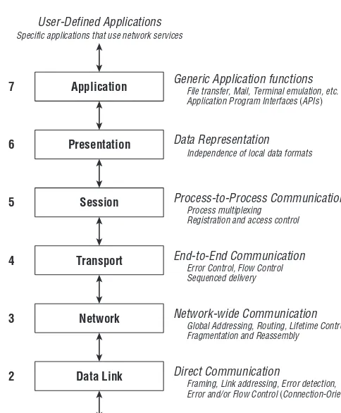
Figure 1-1 depicts the Open Systems Interconnect (OSI) model of network layering developed during the late 1970s and formally standardized in [ISO94]. It comprises seven layers of network system functions.
Data Representation Independence of local data formats Application
7
6 Presentation
5 Session
4 Transport
3 Network
2 Data Link
1 Physical
Process-to-Process Communication Process multiplexing
Registration and access control
End-to-End Communication Error Control, Flow Control Sequenced delivery
Network-wide Communication Global Addressing, Routing, Lifetime Control Fragmentation and Reassembly
Direct Communication
Framing, Link addressing, Error detection,
Error and/or Flow Control (Connection-Oriented Links only)
Physical Channel Access
Line Drivers/Receivers, Encoder/Decoders, Timing Generic Application functions
File transfer, Mail, Terminal emulation, etc. Application Program Interfaces (APIs) User-Defined Applications
Specific applications that use network services
Figure 1-1OSI reference model for network communications
In the sections that follow, we will take a look at the functions provided by each of these layers, with particular concern for their relevance to LANs and LAN switches.
1.1.1 Physical Layer
Examples of Physical layer interfaces are Token Ring, Ethernet, and FDDI. The Physical layer is also concerned with the actual transmission medium, such as network connectors, cabling types, cabling distance factors, and other mechanical considerations.
While a given networking device (for example, a LAN switch) must obvi-ously include the circuitry needed to connect to the communications channel on which it is to be used, the nature of that channel has little impact on the higher-level operation of the device. For example, a LAN switch performs the same functions regardless of whether it is connected to an optical fiber chan-nel operating at 1,000 Mb/s or a twisted pair copper wire chanchan-nel operating at 10 Mb/s.
1.1.2 Data Link Layer
The Data Link layer provides services that allow direct communication between devices across the underlying physical channel. The communica-tion can be point-to-point in nature (exactly two communicating stacommunica-tions) or point-to-multipoint (one-to-many), depending on the nature and configuration of the underlying channel.
In general, the Data Link layer must provide mechanisms for:
Framing: The Data Link typically must provide a way to separate (delimit) discrete message transmissions (frames) in the Physical layer symbol stream.
Addressing: Particularly when communicating among multiple stations on a common communications channel (as is typical of LANs), there must be a means to identify both the sender and target destination(s).
Error detection: It is theoretically impossible for the underlying communications channel to be totally error free. While we hope that most transmissions will be received intact, there is always some residual rate of data errors, regardless of the technology employed within the Physical layer.2It is important that corrupted data not be delivered to
higher-layer clients of the Data Link. At a minimum, the Data Link layer must detect virtually all errors. Depending on the design of the Data Link, it may either discard corrupted data (leaving error recovery to higher-layer entities) or take explicit action to correct or recover from the
data corruption. These two modes of operation are explored in detail in section 1.1.8.1.
In general, LAN technology exists primarily at the Data Link and Physical layers of the architecture. Likewise, the functions performed by a LAN switch occur mainly at the Data Link layer.3As a result, this book focuses heavily on
Data Link operation and behavior. Throughout the book, we show you how LAN switches significantly enhance the power and capabilities provided by the Data Link layer. As part of the design of these new features and the devices that implement them, you must often consider the impact of such Data Link modifications on the operation of higher-layer protocols.
Because it is so crucial to your understanding of LANs and LAN switching, section 1.1.8 provides an in-depth look at Data Link layer operation.
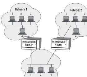
1.1.3 Network Layer
While the Data Link is concerned with the direct exchange of frames among stations on a single communications channel, the Network layer is responsible for station-to-station data delivery across multiple Data Links. As such, this layer must often accommodate a wide variety of Data Link technologies (both local and wide area) and arbitrary topologies, including partially complete meshes with multiple paths between endpoints. The Network layer is respon-sible for routing packets across the internetwork, usually through the action of intermediate relay stations known as routers (see section 1.5.3).4
Examples of Network-layer protocols include the Internet Protocol (IP) used in the TCP/IP suite, the Internetwork Packet Exchange protocol (IPX) used in NetWare, and the Datagram Delivery Protocol (DDP) used in AppleTalk.
1.1.4 Transport Layer
In most network architectures, Transport is where the buck stops. While the underlying communications facilities may cause packets to be dropped, delivered out of sequence, or corrupted by errors, the Transport layer shields higher-layer applications from having to deal with these nasty details of network behavior. Transport provides its clients with a perfect pipe: an error-free, sequenced, guaranteed-delivery message service that allows process-to-process communications between stations across an internetwork, as long as a functioning communications path is available.
3Chapter 4 discusses the operation of so-called multilayer switches (MLS), which implement functionality at other layers.
4Pronunciation guide: rou-ter (ro o ’ter) noun
A device that forwards traffic between networks. rou-ter (rou’ter) noun
Seifert’s Law of Networking #42
The Layers Keep Lifting Me. . .
Higher and Higher.
To provide this end-to-end reliable delivery service, Trans-port often needs to include mechanisms for connection establishment, error recovery, traffic pacing (flow control), message sequencing, and segmentation/reassembly of large application data blocks. Examples of Transport protocols include the Transmission Control Protocol (TCP) of the TCP/IP suite, the Sequenced Packet Exchange (SPX) protocol of NetWare, and the AppleTalk Transaction Protocol (ATP).
1.1.5 Session Layer
The Session layer provides for the establishment of communications sessions between applications. It may deal with user authentication and access control (for example, passwords), synchronization and checkpointing of data transfers, and so on. The Session layer serves requests from the Presentation layer and sends requests to the Transport layer.
The Session layer sets up, manages, and ultimately terminates communi-cation between end users and end user applicommuni-cations. It is able to combine different data stream types coming from various sources and synchronize the data so the end users can all be on the same page (so to speak).
Examples of some of the more well-known protocols that provide services related to this layer are: Network Basic Output System (NetBIOS), Network File Systems (NFS), Secure Shell (SSH), Structured Query Language (SQL), Real-time Transport Protocols, and. . .well, you get the drift.
1.1.6 Presentation Layer
The Presentation layer is responsible for the problems associated with commu-nication between networked systems that use different methods of local data representation. When implemented, this layer allows data to be exchanged between machines that store information in different formats while main-taining consistent semantics (the meaning and interpretation of the data). The Presentation layer serves requests from the Application layer and sends requests to the Session layer.
1.1.7 Application Layer
The Application layer provides generic application functions, such as elec-tronic mail utilities, file transfer capability, and the like. It also provides the Application Program Interfaces (APIs) that allow user applications to com-municate across the network. Note that, contrary to popular belief, the QSI Application layer does not include the user’s networking applications; from an architectural perspective, end user applications reside above the OSI reference model altogether. The Application layer provides the facilities that allow user
Seifert’s Law of Networking #6
Network architecture — where the rubber
met the sky!
applications to easily use the network protocol stack — that is, generic application services and programming interfaces.
From the perspective of a LAN switch operation, you rarely need to consider the operation of protocols above Transport. A well-designed and functioning Transport implementation effectively shields the higher layers from all of the vagaries of networking.
1.1.8 Layering Makes a Good Servant but a Bad Master
Many people in the networking industry forget that the industry-standard layered architecture is not the OSI reverence model, to be worshipped, but a reference model, to be used as a basis for discussion. They believe that the standard model is like the Seven Commandments passed down from a network deity, and that any system that does not conform to the structure of the model is evil, or at least fundamentally flawed. This is complete and utter nonsense. The model is just that: a model for describing the operation of networks. It is not a standard to which networking protocols must adhere, or an engineering specification to which network components or devices must conform. The OSI reference model provides you with a common framework to discuss and describe the complete set of functions that may be performed in a practical network implementation. It should not, however, constrain any implementation from doing what is appropriate and right for its target application environment. Architectural purity may look nice on paper, but it doesn’t make a system work properly.
In particular, our understanding of layered architecture should always be tempered by the following:
machines, there is no real need for a Presentation layer because ASCII is universally understood. The layer can be eliminated completely with no loss of functionality. The standard TCP/IP protocol suite eliminates both the Session and Presentation layers, yet it works quite well.5
Any function not performed at one layer can be pushed up to a higher layer. Just because a network system does not implement some OSI-prescribed function in an exposed module using the OSI name for that layer does not mean that the system must live without the use of that function. For example, if a protocol suite does not include a Presentation layer, this does not imply that all communicating systems must use the same method of local data representation.6
Lacking a Presentation layer, the burden of data format conversion between dissimilar systems just becomes the responsibility of the application that is providing the data transfer. This is, in fact, common practice.
Don’t confuse architecture with implementation. Even if the architecture of a network device can be presented in a layered fashion according to the OSI model, this does not mean that the implementation of that device must necessarily be partitioned according to the architectural layering. Architecture defines the functional boundaries of a system. Implementa-tion should follow technology boundaries. In many cases, it is perfectly acceptable for software modules to cross layer boundaries. A single segment of code may implement the functionality described by multiple layers; there may be no exposed interfaces between certain layer entities. The tradeoff here is modularity versus performance. In a system highly constrained by processing power and/or memory, it may even be nec-essary and appropriate to write an entire protocol stack in one software module.7
This dichotomy between architecture and implementation is true for the hardware as well as the software components of a system. For example, many manufacturers produce integrated circuits designed to provide an interface to a local area network (LAN chip sets). Rarely does it make sense to build a ‘‘Data Link chip’’ and a ‘‘Physical layer chip.’’ The partitioning of functions between
5To be fair, TCP subsumes some of the OSI Session layer functions into the Transport layer. 6This is a good example because the Presentation layer is rarely implemented as shown in the OSI reference model.
devices in a chip set is determined by technology (analog versus digital process, clock domains, and so on), power consumption, and portability to multiple device applications rather than by any arbitrary layering prescribed by the OSI model.
An application can use the network at any layer, not just the Application layer. Just because the OSI model defines one layer specifically for application interfaces does not mean that real applications must use that layer as their entry point to the network. An application can access network services at any layer in the hierarchy as long as it is willing to accept the level of service provided at that layer. For example, an application that operates across only a single link can interface directly to the Data Link layer; there is no need to incur the overhead of Network and higher-layer processing if those functions are not needed by that particular application.
Similarly, there is no need for communications to pass through every layer between an entity and the underlying physical channel, even if they exist in the protocol suite in use. Layers can be skipped if the functionality adds no benefit. Figure 1-2 depicts an example of a multi-protocol end station architecture incorporating TCP/IP, Local Area Transport (LAT), AppleTalk, and IPX. Note that not all seven layers are present in any of these protocol suites. In addition, many higher-layer protocols and applications skip layers where appropriate, and some modules encompass the functionality of multiple layers.
Figure 1-2Multi-protocol layered architecture example
system; implementation is how we actually build it. Neither one should control the other. In fact, no popular network system in use today exactly maps, module-for-module, to the OSI model. Any attempt to build such a system (or to describe a system as if it did map this way) is futile; this is not the purpose of the model.
1.1.9 Inside the Data Link Layer
Because this is a book about LAN switches, we need to examine the innards of the Data Link more than any other layer in the architecture. In this section, we look at the different modes of Data Link layer operation, the architectural subdivision of the Data Link layer, and the operation of the Logical Link Control protocol (LLC).
1.1.9.1 Modes of Operation
Data Links can operate in either of two basic modes: connectionless or connection-oriented.
1.1.9.1.1 Connectionless Operation
A connectionless link provides best-effort service; frames are sent among devices and should be properly received with high probability, but no guar-antees are made and no mechanisms are invoked to recover from errors if they do occur. Error detection will prevent corrupted frames from being delivered to a higher-layer client (to the level of robustness provided by the error check algorithm). However, in the event of an error, it is not the connectionless Data Link’s responsibility to invoke retransmissions or other recovery mechanisms; connectionless links do not provide error control.
Similarly, if a target destination is unable to receive a frame due to lack of resources (for example, buffer memory), it is not a connectionless Data Link’s responsibility to recover from this loss, or even to prevent transmission when such resources are not available; connectionless links do not normally provide flow control.
1.1.9.1.2 Connection-Oriented Operation
A connection-oriented link usually provides for both error and flow control between the communicating partners. In general, this will require that the partners maintain a certain amount of state information about this ongo-ing stream of information beongo-ing exchanged. In the event of an error, there must be some way to identify the particular frame(s) that were not received and to request their retransmission. Thus, sequence numbers are usually assigned to frames, and the communicating stations must keep track of which frames were received and which are either in process or require retransmission. Prior to information exchange, partners in a connection-oriented link must generally invoke a call setup procedure, which establishes the link and ini-tializes the sequence state information. Once set up, data can be exchanged, with error and/or flow control procedures operating to ensure orderly and error-free exchange during the course of the call. Once completed, the call can be torn down and the resources made available for other communications.
A connection-oriented link operates closed loop; once a connection is estab-lished, there is a continual exchange of data and feedback control information in both directions. Errors and frame loss can be corrected relatively quickly; the loop time constant need only accommodate the processing and propagation delays of the single link over which communication is occurring.
1.1.9.1.3 Connectionless Versus Connection-Oriented Operation
A connectionless link provides no guarantees regarding frame delivery to the target destination(s). Frames will be delivered with high probability, but there are sure to be some frames that are not delivered because of errors in the physical channel or buffer unavailability at a receiver. A connection-oriented link provides some assurance of proper data delivery to its client — unless the physical channel is inoperative (there is nothing that a Data Link protocol can do to deliver data across a non-functioning channel!). As always, there is no free lunch; a price must be exacted for this assurance, as explained in the following list:8
Protocol complexity: The link protocol must necessarily be more complex for a connection-oriented link than for a connectionless link. A connectionless protocol can consider each frame completely independent of any other. A connection-oriented protocol must generally provide mechanisms for frame sequencing, error recovery, and flow control. Typically, this involves a Positive Acknowledgment and Retransmission (PAR) protocol for error recovery and either a
sliding window or buffer credit scheme for flow control. In addition, the connection-oriented protocol needs facilities for call setup and teardown, and possibly for restoration of a disrupted call.
Station complexity: Stations participating in a connection-oriented link protocol must implement all of the functions demanded by that protocol (call setup/teardown, error control, flow control, and so on). For performance reasons, these functions are generally implemented in hardware within the link controller; the delay imposed by a software-based connection-oriented link protocol implementation is often unacceptable, particularly on high-speed links. This additional hardware adds to the cost of the link controller in every station using the protocol.
Connection-orientation: The use of a connection-oriented link proto-col presumes a connection orientation on the part of the higher-layer protocols and/or applications in the system. A connection-oriented link protocol may be appropriate if the communication indeed comprises a long-term stream of information exchanges. However, if the communicating applications exchange information only sporadically, the overhead of call setup and maintenance can be excessive. Examples of such sporadically communicating applications include most Network-layer routing protocols (RIP, OSPF, and so on) and infrequent polling of devices for network management statistics (SNMP).
Connectionless links are uncomplicated; minimal overhead is required in the frames exchanged, and the link hardware can be simpler and therefore lower in cost. Whether connectionless operation is acceptable depends primarily on the probability that frames will be delivered properly under normal operation. If the vast majority of frames are successfully delivered, connectionless operation is incredibly efficient. For the boundary case of a missing frame, higher-layer protocol mechanisms can still recover and maintain reliable delivery for the client application(s). Performance will suffer when errors occur, but if errors do not occur often, the effect is insignificant.
The communications channel in a LAN environment is generally of exceed-ingly high quality. Unlike long-distance telephony circuits, microwave links, or satellite channels, LANs generally operate over carefully designed media in a controlled environment. The error rates encountered in a typical LAN are on the order of 1×10–12 or better. For a workgroup average frame length of
534 bytes [AMD96], this implies 1 lost frame due to bit errors for every 234 million frames sent. The complexity and overhead of a connection-oriented link are not easily justified for this level of errors. If the communications channel were an error prone wide area network (WAN) link with an error rate of 1× 10⁻⁶ (one bit in a million in error), there would instead be 1 lost
frame for every 234 frames sent. This is a much more significant level of frame loss and could easily justify the complexity of a connection-oriented Data Link protocol.
Thus, LANs generally use connectionless Data Link protocols. The notable exception is the IBM LAN architecture and its use of Token Ring; this is discussed in detail in Chapter 3, ‘‘Bridging Between Technologies,’’ and Chapter 6, ‘‘Source Routing.’’
1.1.9.2 Data Link Sublayering
LANs are somewhat special in that they often comprise a shared channel among many stations (as opposed to a point-to-point link, as provided by a telephony T-carrier). That is, in addition to providing a connectionless or connection-oriented service to its client, a LAN generally requires some means to arbitrate among the stations for use of the shared, common channel.
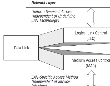
Thus, we separate the Data Link layer into two distinct sublayers, as depicted in Figure 1-3:
Logical Link Control (LLC): This upper sublayer provides the Data Link service (connectionless or connection-oriented) to the higher-layer client, independent of the nature of the underlying LAN. In this manner, higher layer clients are relieved from having to deal with the details of the particular LAN technology being employed. They can use the same service interface to the Data Link, whether it is operating over an Ethernet, Token Ring, FDDI, or other technology.9
Medium Access Control (MAC): This lower sublayer deals with the details of frame formats and channel arbitration asso-ciated with the particular LAN technology in use, independent of the class of service being provided to higher-layer clients by LLC.
Data Link
Logical Link Control (LLC)
Medium Access Control (MAC)
Uniform Service Interface
LAN Technology) (Independent of Underlying
Network Layer
LAN-Specific Access Method (Independent of Service Interface)
Physical Layer
Figure 1-3Data Link sublayering
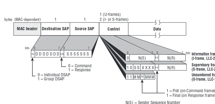
1.1.9.3 Logical Link Control
The Logical Link Control protocol was developed and standardized within the IEEE 802.2 Working Group (see section 1.4.1) and provides for three types of service:
LLC Type 1: Connectionless Service. This is a simple, best-effort deliv-ery service. LLC-1 provides no call setup or maintenance procedures, no error recovery, and no flow control. The only protocol mechanism provided is for multiplexing of the Data Link to multiple higher-layer clients.
LLC Type 2: Connection-Oriented Service. LLC-2 was derived directly from the High-Level Data Link Control protocol (HDLC) commonly used on wide area telecommunications links [IS093, ANSI79]. It operates from the same set of principles; the main differ-ences are a reduction in the number of connection modes available and the inclusion of both source and destination client identifiers. LLC-2 includes procedures for call establishment and teardown, error recovery using Positive Acknowledgment and Retransmis-sion, and flow control using a fixed-length sliding window of eight frames. Devices that implement LLC-2 must also implement LLC-1; connectionless operation is used to establish LLC-2 connections.