MediaTek LinkIt™ Assist 2502 Developer's
Guide
Version:
1.1
Document Revision History
Revision Date Description
1.0 9 April 2015 Initial release
Table of contents
1. Introduction ... 1
1.1. What is MediaTek LinkIt? ... 1
1.2. MediaTek LinkIt Assist 2502 development platform ... 2
1.3. Related development platforms ... 11
1.4. Joining the MediaTek Labs Ecosystem...12
2. Getting started ... 13
2.1. Environment ...13
2.2. Installing Eclipse IDE for C/C++ Developers ...13
2.3. Installing LinkIt Assist 2502 SDK 2.0 ...13
2.4. Updating the Firmware ... 17
2.5. Creating Your First Project ... 19
2.6. Compiling and Uploading to Hardware ... 22
2.7. Running your Project ... 23
2.8. Using the example applications ... 23
2.9. Using the LinkIt Toolbar ... 26
3. Troubleshooting ...32
3.1. The LinkIt Assist 2502 development board fails to powerup after attaching the USB cable... 32
3.2. VXP Fails to Upload ... 32
3.3. Wi-Fi AP Doesn’t Display After Scanning ... 32
3.4. GSM Function Isn’t Working...33
3.5. GPRS Function Isn’t Working...33
4. Programming Guide ...33
4.1. Bootup procedure...33
4.2. LinkIt Assist 2502 Application Entry and Exit Point ...35
4.3. Event-driven Programming Model ...35
4.4. Threads ... 36
4.5. Memory Layout of a LinkIt Assist 2502 Application ... 36
4.6. Log and Command ... 38
4.7. Hardware Peripheral and Driver Functions ... 38
4.8. Application Resource ... 40
4.9. Power Management ... 44
4.10. Porting Arduino Sketches and Drivers ... 44
5.16. GNSS ... 72
5.17. Graphics... 73
5.18. VXP and Firmware Update ... 74
Lists of tables and figures
Table 1 Specification of the LinkIt Assist 2502 development board ... 6
Table 2 Comparison of the LinkIt ONE and Assist 2502 development boards... 7
Table 3 Summary of LinkIt 2502 API modules ... 8
Table 4 The functions available to enable and disable hardware components... 44
Table 5 HTTPS callback functions ... 66
Figure 1 Wearables and IoT product segments ... 1
Figure 2 The components of the MediaTek LinkIt Assist 2502 development platform ... 2
Figure 3 LinkIt Assist 2502 development board (back view) ... 3
Figure 4 LinkIt Assist Development Board (front view) ... 4
Figure 5 Pin-out diagram of the LinkIt Assist 2502 development board ... 5
Figure 6 The LinkIt Assist 2502 SDK 2.0 installation application ... 14
Figure 7 The welcome page of the SDK setup wizard. ... 14
Figure 8 Selecting the folder in which Eclipse IDE is installed ... 15
Figure 9 Option to move SDK to a permanent location ... 15
Figure 10 The Ready to Install page of the setup wizard ... 16
Figure 11 Final page of the SDK installer ... 16
Figure 12 LinkIt ONE in mass storage mode ... 17
Figure 13 LinkIt Firmware Updater launch screen ... 17
Figure 14 The firmware being uploaded to your device ... 18
Figure 15 Firmware Updater Download Complete screen ... 18
Figure 16 Creating new LinkIt Assist 2502 application ... 19
Figure 17 Selecting the LinkIt 2.0 application ... 19
Figure 18 Selecting the right hardware platform ... 20
Figure 19 LinkIt Assist 2502 libraries ... 21
Figure 20 Your First LinkIt Assist 2502 Application ... 22
Figure 21 LinkIt toolbar in Eclipse IDE ... 22
Figure 22 Build Application toolbutton in the LinkIt toolbar ... 22
Figure 23 LinkIt Console in Eclipse ... 23
Figure 24 Selecting LinkIt Assist 2502 example code ... 24
Figure 25 Creating a new LinkIt Assist 2502 application ... 25
Figure 26 LinkIt example code list ... 26
Figure 27 Application Settings toolbutton ...27
Figure 28 Project information window ...27
Figure 29 The Build Application toolbutton ... 28
Figure 30 The Resource Editor toolbutton ... 28
Figure 31 Monitor Icon... 28
Figure 34 Connecting the COM port ... 29
Figure 35 Hardware Connection Log ... 30
Figure 36 Log Filter window ... 30
Figure 37 Send Command window ... 30
Figure 38 Disconnect toolbutton... 31
Figure 39 API Reference Icon ... 31
Figure 40 The bootflow sequence ... 34
Figure 41 Memory Layout of an application ...37
Figure 42 Sending command in Monitor tool ... 38
Figure 43 Send Command dialog box ... 38
Figure 44 Resource Types ... 41
Figure 45 Selecting the Images resource type ... 41
Figure 46Image resource example ... 41
Figure 47 Select image file ... 42
Figure 48 The save toolbutton... 42
Figure 49 Selecting Strings resource type ... 42
Figure 50 Selecting language for string resources ... 43
Figure 51 Select the languages to be included in the string resources ... 43
Figure 52 Edit text for selected language ... 43
Figure 53 Import/Export String resources... 44
Figure 54 Selecting the import source ... 45
Figure 55 Selecting custom/arduino as the root directory ... 46
Figure 56 Importing Arduino sketch code by copying it ... 46
Figure 57 Importing peripheral drivers ... 47
Figure 58 Adding the required #define statements ... 47
Figure 59 Application Settings ... 52
Figure 60 Tag settings in Application Settings ... 56
Figure 61 Examples of resource identifiers ...57
Figure 62 Mapping Pin Name to Pin Number ... 59
1.
Introduction
1.1.
What is MediaTek LinkIt?
MediaTek LinkIt™ is a collection of development platforms designed for the prototyping of Wearables and Internet of Things (IoT) devices. Each development platforms provide a collection of tools, hardware and related resources to enable developers to address one of the three Wearables and Internet of Things (IoT) device sectors, as shown in Figure 1.
One Application Use focusing on 1 task (such as sports, health, find device,
Each development platform turn offers one or more chipset and API variants designed to meet specific development and device requirements. To enable the creation devices prototypes, each developer platform includes:
• One or more HDKs consisting of a development board and one of more chipset modules to enable the prototyping of devices.
• An SDK to enable the creation of firmware or software for devices.
• One or more hardware reference designs that can be used as the basis for board layouts of final products.
• Comprehensive documentation, such as API references, developer guides, chipset descriptions and pin-out diagrams.
• Support forums.
1.2.
MediaTek LinkIt Assist 2502 development platform
The MediaTek LinkIt Assist 2502 development platform is designed to enable the prototyping of Simple Application Use (SAU) Wearables and IoT devices. These devices include smartwatches, toddler and senior trackers, smart wrist bands and healthcare wearable devices.
As shown in Figure 2 this development platform consists of a SOC, API, hardware development kit (HDK), software development kit (SDK) and is supported by comprehensive documentation.
Figure 2 The components of the MediaTek LinkIt Assist 2502 development platform
This SOC also works with MediaTek’s energy efficient Wi-Fi (MediaTek MT5931) and GNSS (MediaTek MT3332) companion chipsets.
1.2.2.
LinkIt Assist 2502 Hardware Development Kit (HDK)
The LinkIt Assist 2502 HDK consists of:
• LinkIt Assist 2502 development board from Seeed. The board provides access to the hardware LCD engine of MediaTek MT2502 SOC, making it suitable for prototyping wearable devices.
• LinkIt Assist 2502 modules by AcSiP that includes:
o LinkIt Assist 2502 module (AcSiP module model number AI2502S05)
o LinkIt Assist 2502 GNSS module (AcSiP module model number CW03S)
o LinkIt Assist 2502 Wi-Fi module (AcSiP module model number CW01S)
1.2.2.1. LinkIt Assist 2502 development board
The LinkIt Assist 2502 development board incorporates the three LinkIt Assist 2502 modules, as shown in Figure 3, and display, pins and buttons, as shown in Figure 4.
Figure 4 LinkIt Assist Development Board (front view)
Each MediaTek Assist 2502 module include a MediaTek SOC and related RF components to provide an easy-to-use hardware interface. The schematic, layout and BOM for each module are available for you to use in designing your own MT2502 product using modules. Hardware development cycle can be shortened by reference to this reference design based on modules, and make shorter time-to-market possible.
This platform provides a full-range of communication, positioning and multimedia features. This make it suitable for design and development an wide array of wearable devices such as watches, wristbands, trackers, and other mobile IoT devices. Communication protocols GSM, GPRS,
It is also easy to attach the peripheral devices that might be needed to prototype the final product through interfaces that include GPIO, analog, PMW, I2C, SPI, UART and Xadow. The available pins are illustrated in Figure 5.
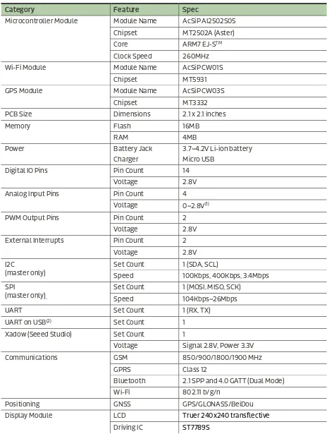
The full specification of the LinkIt Assist 2502 development board is provided in Table 1.
Table 1 Specification of the LinkIt Assist 2502 development board
Category Feature Spec
Microcontroller Module Module Name AcSiP AI2502S05
Chipset MT2502A (Aster)
Core ARM7 EJ-STM
Clock Speed 260MHz
Wi-Fi Module Module Name AcSiP CW01S
Chipset MT5931
GPS Module Module Name AcSiP CW03S
Chipset MT3332
External Interrupts Pin Count 2
Voltage 2.8V
Voltage Signal 2.8V, Power 3.3V
Communications GSM 850/900/1800/1900 MHz
GPRS Class 12
Bluetooth 2.1 SPP and 4.0 GATT (Dual Mode)
Wi-Fi 802.11 b/g/n
Positioning GNSS GPS/GLONASS/BeiDou
Display Module LCD Truer 240x240 transflective
1.2.2.2. Related HDKs
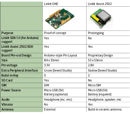
The LinkIt ONE development board is also based on the MediaTek MT2502 SOC. It’s possible to use this board to run MediaTek LinkIt Assist 2502 applications, with some limitations.
A comparison of the development boards is provided in Table 2.
LinkIt ONE LinkIt Assist 2502
Purpose Proof of concept Prototyping
LinkIt SDK 1.0 (for Arduino)
Board Pin-out Design Arduino-style Pin Layout Proprietary Design
Size 84 x 53mm 53 x 53mm
Pin voltage 3.3V 2.8V
Extra Peripheral Interface Grove (Seeed Studio) Xadow (Seeed Studio)
Build-in Key 0 2
SD Card Yes No
SIM SIM Micro SIM
Power Source Micro USB (5V)
Battery (optional)
Micro USB (5V) Battery (required)
Audio Headphone (inc. mic) Headphone, speaker, mic
Vibrator No Yes
Antenna External Build-in ceramic antenna
Table 2 Comparison of the LinkIt ONE and Assist 2502 development boards
For more information on the LinkIt ONE development board, please see the MediaTek LinkIt™ ONE Developer’s Guide.
To be compliant with Arduino, the design of the LinkIt ONE development board includes special circuits, for example to shift pin voltage from 2.8V to 3.3V, which would add unnecessary cost if incorporated into a final product. Those circuits are therefore not included in the LinkIt Assist 2502 development board.
1.2.3.
LinkIt Assist 2502 API
As shown in Figure 2 the LinkIt Assist 2502 API is used to create a LinkIt Assist 2502 application in the LinkIt Assist 2502 SDK. Coding is undertaken using the C programming language based API functions, as well as third party libraries and device drivers. The application is compiled into a LinkIt Assist 2502 executable file (VXP file) and executes in the runtime environment provided by the firmware of the LinkIt Assist 2502 development board. Dynamic loading is supported to run applications from flash storage.
It’s possible to develop LinkIt Assist 2502 software in C++ as the toolchain supports compilation in both C and C++ files. If you want to code in C++, rename the application source code file from
*.c to *.cpp after generating your project. However, note that the LinkIt Assist 2502 API provides C functions rather than C++ functions and some C++ libraries may rely on runtime functions that are not supported by the LinkIt Assist 2502 development platform.
LinkIt Assist 2502 applications are executed in a multi-threaded environment. In this
environment, there are system-managed threads such as driver threads that are responsible for managing integrated hardware such as the GSM modem and Bluetooth protocol stack. A LinkIt Assist 2502 application runs on a specific thread called main thread. LinkIt Assist 2502
applications can also create new threads. However, most LinkIt Assist 2502 SDK 2.0 API functions can only be invoked from the main thread. Functions that are called on created threads are explained in detail in the API reference documentation.
Due to the nature of multi-thread, multi-tasking environment, LinkIt Assist 2502 applications adopt an event-based programming model. More information about this programming model is provided in 5.5.5, “Threads”.
1.2.3.1. API Summary
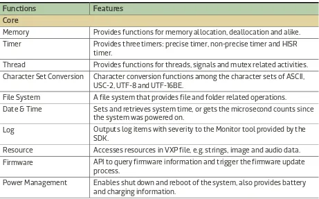
Table 3 shows a summary of the modules available in the LinkIt 2502 API.
Table 3 Summary of LinkIt 2502 API modules
Functions Features
Core
Memory Provides functions for memory allocation, deallocation and alike.
Timer Provides three timers: precise timer, non-precise timer and HISR timer.
Thread Provides functions for threads, signals and mutex related activities.
Character Set Conversion Character conversion functions among the character sets of ASCII, USC-2, UTF-8 and UTF-16BE.
File System A file system that provides file and folder related operations.
Date & Time Sets and retrieves system time, or gets the microsecond counts since the system was powered on.
Log Outputs log items with severity to the Monitor tool provided by the SDK.
Resource Accesses resources in VXP file, e.g. strings, image and audio data.
Firmware API to query firmware information and trigger the firmware update process.
Functions Features
User interaction
Keypad Registers keypad event handlers, if the HDK provides keypad hardware.
Touch Registers touch event handlers, if supported by HDK and firmware.
Interfaces and network
Driver Common Layer Provides functions to control and access (read and write) to the hardware devices, including ADC, GPIO, I2C, SPI, UART, EINT, PMU and PWM.
Network Protocol Provides TCP, UDP, SSL, HTTPS and HTTP support.
Telephony and mobile data
SIM Functions to access the information from the SIM card in the device.
Telephony Functions to control voice calls.
SMS Functions to send, read, delete and cancel SMS messages.
Cellular Info Functions to obtain current or neighboring cell information.
GPRS Configures the GPRS connection.
Wi-Fi
WLAN Configures WLAN (Wireless LAN).
Location
GPS GPS and Extended Prediction Orbit (EPO) functionality
Bluetooth
Bluetooth Functions for applications to configure, monitor and search for Bluetooth 2.1 connections. The Bluetooth SPP API supports client and server functionality for one-to-one connections.
Notification Service Functions to receive notifications from iOS and Android devices.
Bluetooth Low Energy Provides Bluetooth 4.0 Generic Attribute Profile (GATT) support.
Graphics
Graphics Performs pixel operations
Draws points, lines, rectangles and ellipses Decodes and paints images
Outputs text using vector font
Performs LCD operations on supported hardware
Audio
Audio Play and record audio files
1.2.3.2. Related APIs
In addition to the core API, the LinkIt Assist 2502 development platform can also make use of:
• LinkIt Smart Connection libraries for Android and iOS, which provide for broadcasting wireless AP setting from a smartphone or tablet to a LinkIt 2502 development board or device. For more information see LinkIt Smart Connection Developer’s Guide.
1.2.4.
LinkIt Assist 2502 Software Development Kit (SDK)
The MediaTek LinkIt Assist 2502 SDK 2.0 enables the creation of application (software) for the development platform. A details guide to using the SDK is provided in 2, “Getting started”.
1.2.4.1. Feature summary
The SDK consists of the following:
• Firmware Updater that uploads matching version of the firmware to the development boards. The SDK provides firmware in binary format.
• A plug-in for the Eclipse IDE (with CDT) that provides:
o Eclipse Project Launcher Wizard that creates a project skeleton for you to start programming your LinkIt Assist 2502 applications.
o Eclipse Tool Bar that defines the proper application settings and compile options for the compiler to build the VXP executable for your LinkIt Assist 2502 applications.
o Resource Editor that enables you to embed images and strings into the VXP executable that can be retrieved by the Resource module of the SDK.
• Uploader that uploads the VXP executable to your connected development board through the USB port.
1.2.4.2. Development process overview
You start creating a LinkIt 2502 applications using the Eclipse Project Launcher Wizard to create a project skeleton or open an example project. The application is codes with the Eclipse CDT tools and the compiled and linked from options on the Eclipse Tool Bar.
The generated executable (VXP) is uploaded to the internal storage of the development board with the Uploader tool. Next, the firmware on the development board reboots, and the uploaded application executes to enable access to the features of the underlying frameworks and built-in drivers.
1.2.5.
Documentation and code examples
There are five references available to assist with the development of software for LinkIt Assist 2502 prototypes:
• This developer’s guide, the latest copy of which is available here on the MediaTek Labs website.
• LinkIt Smart Connection Developer’s Guide: This document provides information on how to use Smart Connection to provision the Wi-Fi connection on a LinkIt development board and connect to a wireless AP. It includes details on how to use the Android and iOS
• LinkIt Assist 2502 development board pin-out diagram: This diagram provides details of the pin breakout on the development board.
• LinkIt Assist 2502 API reference: Details of the various modules, their functions and parameters, available for coding software for the development platform.
• Example code supplied as part of the SDK and accessible through the Eclipse Project Wizard.
In addition there are a number of resources available to assist with the creation of final device hardware boards:
• LinkIt Assist 2502 Hardware Reference Design: This file includes:
o LinkIt Assist 2502 development board schematic and layout
o LinkIt Assist 2502 development board pin-out diagram
o LinkIt Assist 2502 pin mux table
o LinkIt Assist 2502 module data sheets (AcSiP)
o Chipset datasheets
Please note: PCB layout and board schematics have been created using Eagle. They can be viewed using the freeware Eagle Light Edition.
• MT2502 (Aster) chipset technical brief
• MT3332 (GNSS) chipset technical brief
• MT5931 (Wi-Fi) chipset technical brief
• LinkIt Assist 2502 module data sheet (AcSiP AI2502S05)
• LinkIt Assist 2502 GNSS module data sheet (AcSiP CW03S)
• LinkIt Assist 2502 Wi-Fi module data sheet (AcSiP CW01S)
Additional documentation may become available from time to time and can be found on the development platforms documentation page on the MediaTek Labs website.
1.3.
Related development platforms
The MediaTek LinkIt ONE development platform is also based on the MediaTek MT2502 chipset. However, LinkIt ONE development platform provides for use of a set of APIs similar to those provided on the Arduino development boards, implements through a porting layer between the Arduino API and the Runtime environment. Software development is enabled by an SDK that offers a plug-in to the Arduino software.
There is also a fundamental between the software architecture of LinkIt ONE application and those for LinkIt Assist 2502. LinkIt ONE programs consists of setup() and loop() functions and it’s common for the system to be in an endless polling state in the loop() function. This
programming style is very straightforward, but has the disadvantage that it keeps the system in a busy state for much of the time, which leads to increased power consumption. The LinkIt Assist 2502 programming style however, uses event-based programming that uses power more efficiently. Please see 4.3, “Event-driven Programming Model” for details on the event-based programming model
For information on the LinkIt ONE development platform, please see the MediaTek LinkIt™ ONE Developer’s Guide.
1.4.
Joining the MediaTek Labs Ecosystem
Wearables and Internet of Things are the next wave in the consumer gadget revolution. MediaTek Labs is a key player in this field, combining the best of two worlds — the existing MediaTek
ecosystem of phone manufacturers, electronic device manufacturers and telecom operators combined with an open, vibrant maker and developer community.
No matter whether you’re a maker, device manufacturer, student, DIY hobbyist, or programmer, you will find a development platform from MediaTek to match your requirements to create something innovative. Then you’ll be able to take advantage of the MediaTek Labs Partner Connect program to take your idea to market.
2.
Getting started
This chapter provides a guide to getting started with the LinkIt Assist 2502 development platform and covers the following items:
• The supported environment for development.
• Installing the Eclipse IDE for C/C++ Developers.
• Installing and configuring the LinkIt Assist 2502 SDK 2.0.
• Building your first project and running it on the development board.
• Exploring example code to accomplish specific tasks.
• Using other tools in the SDK.
2.1.
Environment
To make use of the MediaTek LinkIt 2502 SDK and development board please ensure you have a PC with the following:
• Operating system: Microsoft Windows XP, Vista, 7 or 8.
• Eclipse IDE: Indigo (3.7) with CDT 8.0.2.
2.2.
Installing Eclipse IDE for C/C++ Developers
The LinkIt Assist 2502 SDK 2.0 includes a plug-in for Eclipse IDE and is compatible with Eclipse IDE Indigo or higher versions. Please download and install Eclipse IDE from the official Eclipse website
making sure it has the C/C++ development (CDT) plug-in. The IDE installation may require an appropriate JAVA SE version to be installed on your PC.
The LinkIt Assist 2502 Eclipse plug-in needs to be installed in the same folder as the Eclipse IDE, where eclipse.exe is located.
2.3.
Installing LinkIt Assist 2502 SDK 2.0
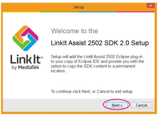
To install LinkIt Assist 2502 SDK 2.0 you need to do the following:
1) Download the LinkIt Assist 2502 SDK 2.0
2) Extract the content of the LinkIt Assist 2502 SDK 2.0 zip file. There are tools in addition to the Eclipse plug-in included in the SDK so consider extracting the content to a permanent location. If you extract the content to a temporary location the installer will give you the option to move it to a permanent location.
4) Double click the LinkIt Assist 2502 SDK 2.0 InstallPlugins as shown in Figure 6.
Figure 6 The LinkIt Assist 2502 SDK 2.0 installation application
5) In the Welcome page, Figure 7, click Next.
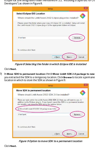
6) In Select Eclipse IDE Location, click Browse and locate the folder in which you installed Eclipse IDE (the designated folder mentioned in 2.2, “Installing Eclipse IDE for C/C++ Developers”) as shown in Figure 8.
Figure 8 Selecting the folder in which Eclipse IDE is installed
Click Next.
7) In Move SDK to permanent location check Move LinkIt SDK 2.0 package to new folder if you extracted the SDK to a temporary location. Click Browse to locate a permanent location in which to store the SDK as shown in Figure 9.
Figure 9 Option to move SDK to a permanent location
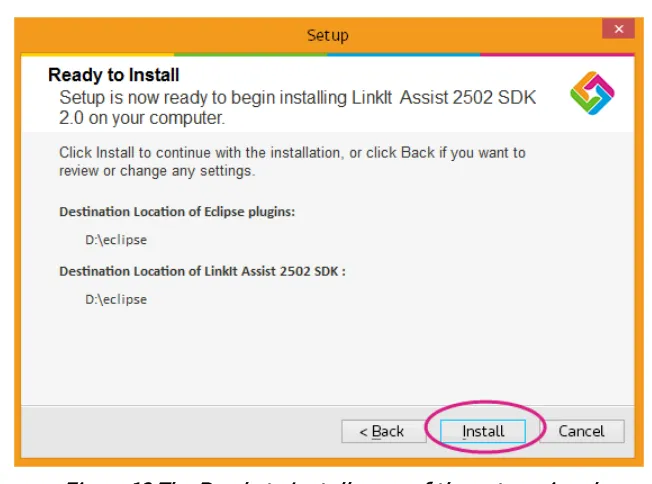
8) In Ready to Install, Figure 10, review the selected file locations and if they are OK click
Install.
Figure 10 The Ready to Install page of the setup wizard
9) Once the plug-in is installed and, if the option was taken, the SDK is moved the
Completing the LinkIt Assist 2502 SDK 2.0 Setup page, Figure 11, displays. Ensure that
Install the MediaTek USB Driver is checked, then click Finish.
Figure 11 Final page of the SDK installer
10) The MediaTek USB driver is now installed and the setup completed.
2.4.
Updating the Firmware
It’s essential to make sure that the firmware of the development board corresponds to the SDK you just installed, before you start programming applications in the Eclipse IDE. To do this you use the Firmware Updater’ to update firmware after installing new versions of SDK. To get started, please make sure the following is ready:
1) If you’ve:
a) A LinkIt Assist 2502 development board, you are good to go.
b) A LinkIt ONE development board, check that it’s switched into mass storage mode, (if you’re using USB as the power source, make sure the USB switch is selected as well) as shown in Figure 12.
Figure 12 LinkIt ONE in mass storage mode
2) Disconnect your LinkIt development board from your PC.
3) Launch LinkIt Firmware Updater.exe, which is located in the SDK folder under
{SDK_path}\tools\FirmwareUpdater\
4) In the LinkIt Firmware Updater window, in Platform select your development board. Then click the green update button, as shown in Figure 13.
5) The firmware is now downloaded to the development board, as shown Figure 14. Do not disconnect the development board from your PC during this process.
Figure 14 The firmware being uploaded to your device
6) When the firmware update is complete this will be confirmed in the Download Complete
page, as shown in Figure 15.
Figure 15 Firmware Updater Download Complete screen
7) Disconnect your LinkIt Assist 2502 development board (if you were updating a LinkIt ONE, switch it back to UART mode) and re-connect it to your PC.
2.5.
Creating Your First Project
Software development and project creation on either LinkIt ONE or LinkIt Assist 2502 development boards requires the same steps, but the results are different.
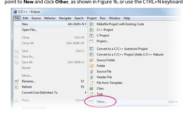
1) The first step is to create a new LinkIt Assist 2502 application. In the Eclipse IDE File menu, point to New and click Other, as shown in Figure 16, or use the CTRL+N keyboard shortcut.
Figure 16 Creating new LinkIt Assist 2502 application
2) The New window displays. Expand the LinkIt 2.0 folder, select Application (*.vxp) and click Next as shown in Figure 17.
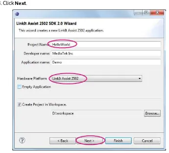
3) The LinkIt Assist 2502 SDK 2.0 Wizard window displays. Change the project name and make sure the Hardware Platform matches your development board, as shown in Figure 18. Click Next.
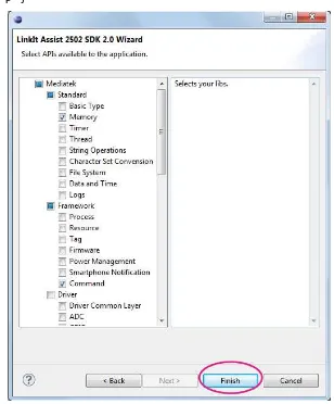
4) The library selection page displays, as shown in Figure 19. The library selection page enables you to include library header files into your project. You can always manually add header files later using the #include command. You can proceed with default libraries for the first project and click Finish.
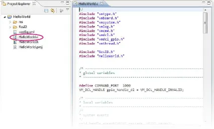
You’ve now created your first LinkIt Assist 2502 application. Open the project from the project explorer pane and double click the *.c file, as shown in Figure 20.
Figure 20 Your First LinkIt Assist 2502 Application
2.6.
Compiling and Uploading to Hardware
An important thing to note before starting this section is that the Build and Debug menu commands and related toolbuttons in Eclipse IDE don’t work for LinkIt Assist 2502 applications. These controls are for C/C++ applications that will run on a PC. Instead, to perform the necessary development tasks use the plug-in toolbar, as shown in Figure 21.
Figure 21 LinkIt toolbar in Eclipse IDE
For more details on the features of the LinkIt toolbar see 2.9, “Using the LinkIt Toolbar”.
To build and upload your application:
1) Make sure your LinkIt Assist 2502 development board is connected to your PC and click the Build Application toolbutton, as shown in Figure 22.
2) The Eclipse IDE will build and upload the application. After it’s finished, the results are displayed in the console pane. To see the build and upload log, change the console view to
LinkIt Console, as shown in Figure 23.
Figure 23 LinkIt Console in Eclipse
2.7.
Running your Project
Once Eclipse has built and installed your application:
• On the LinkIt ONE development board: the LED starts blinking.
• On the LinkIt Assist 2502 development board: the message HelloWorld is shown on the display panel.
Congratulations, you have successfully completed your first LinkIt Assist 2502 SDK 2.0 project.
You can now explore the example applications provided in the SDK.
2.8.
Using the example applications
The LinkIt Assist 2502 SDK 2.0 provides example application projects that you can use to further understand the API or uses as the basis of your own prototypes. Example applications are grouped by folder under {SDK_installation_path}\examples\API.
You can import the examples directly into Eclipse as follow:
1) In the Eclipse IDE File menu, point to New and click Other, or use the CTRL+N keyboard shortcut. The New window displays. Expand the LinkIt Assist 2502 SDK 2.0 Example
folder, select Example Application (*.vxp) and click Next as shown in Figure 24.
2) In the LinkIt Assist 2502 SDK 2.0 Example Wizard give your project a new name and select the right hardware platform, as shown in Figure 25. Click Next.
3) A list of example applications (on the left) and their descriptions (on the right) appear in the LinkIt Assist 2502 SDK 2.0 Example Wizard window, as shown in Figure 26.
Figure 26 LinkIt example code list
4) Select the example you want to load into the application and click Finish.
Eclipse will load the selected example into the application. You can now explore the example and update the code to meet your requirements.
2.9.
Using the LinkIt Toolbar
The LinkIt Toolbar provides access to the LinkIt Assist 2502 application or project settings. The LinkIt toolbar options are as follow:
• Application settings ( )
• Build application ( )
• Resource editor ( )
• Monitor tool ( )
2.9.1.
Application Settings
To define application settings, first select a project in Project Explorer, then click the Application Settings toolbutton, as shown in Figure 27.
Figure 27 Application Settings toolbutton
A window for the specified project displays, as shown Figure 28.
Figure 28 Project information window
The following settings are available:
• User Information
The fields under User Information are properties of your application and they can be queried with an API Tag (please see 5.6, “Tag” for more details). Memory Requirement is an important field as it affects your application’s execution. If the number is set too high or too low, the application may not run. Please see 4.5, “Memory Layout of a LinkIt Assist 2502 Application”, for more information on how to set this value.
• Device Options
These are compiler and linker options used during the build process. You may add other options in this field but removing vital options results in build or execution errors.
2.9.2.
Build Application
The Build Application toolbutton (see Figure 29) initiates the build and upload to hardware processes. The resulting logs for these processes are shown in the LinkIt Console panel.
Figure 29 The Build Application toolbutton
2.9.3.
Resource Editor
The Resource Editor toolbutton (as shown in Figure 30) launches the Resource Editor tool. This tool enables the embedding of audio, video, binary, image and string content into your application. Please see 4.8, “Application Resource” and 5.7, “Resource” for more details on how to use this tool and how to access it with the Resource API.
Figure 30 The Resource Editor toolbutton
2.9.4.
Monitor
The Monitor toolbutton (as shown in Figure 31 ) launches the Monitor tool (see Figure 32) which allows you to capture application logs and send commands to the development board.
To use the Monitor tool:
1) Choose a database file, which is different for each hardware and firmware version. These databases are included in the SDK and you can find them in this path:
{SDK_installation_path}tools\FirmwareUpdater\firmware\LinkIt_Device\{Ha rdware}\{Firmware_version}\database.db
If you choose database file that doesn’t match the hardware, a connection error may result.
2) Next, select the COM port, it is the MTK USB debug port listed in Device Manager, as shown in Figure 33. The port number varies between PCs. Click OK.
Figure 33 Device Manager COM port
3) After selecting the COM port, click the Connect toolbutton to establish a connection with the development board, as shown in Figure 34.
4) The log appears once the connection to the development board is established, you will see the log time, log level, file name and log content, as shown in Figure 35 .
Figure 35 Hardware Connection Log
5) You can also create filters for different log levels with the filter toolbutton, as shown in Figure 36. Click Apply to invoke the filter settings.
Figure 36 Log Filter window
7) To finish, click the Disconnect toolbutton and close the window, as shown in Figure 38. Please note that the COM port remains in use until the Monitor tool is disconnected.
Figure 38 Disconnect toolbutton
2.9.5.
API Reference
The API reference toolbutton (see Figure 39) opens your default browser and takes you to the on-line API reference documentation.
3.
Troubleshooting
This section provides a guide to commonly encountered issues when working with the LinkIt Assist 2502 development board.
3.1.
The LinkIt Assist 2502 development board fails to powerup
after attaching the USB cable
If the LinkIt Assist 2502 development board fails to power up, make sure the battery is attached to the development board. (The LinkIt Assist 2502 development board cannot power on without a Lithium-Ion battery attached. A battery is included in the development board package.) Then, use a micro USB cable to connect the board to a computer and check that the power LED of the board lights. If the LED doesn’t light, it means the board doesn’t have a power supply from the USB cable. In this case, check if the USB cable is connected to a proper power source. Please see Figure 4 on page 5 for PWR LED location on the LinkIt Assist 2502 development board.
If the power LED lights and the board is connected to a computer with USB cable, then you should see a mass storage (removable storage) device displayed in the Computer folder of your
computer. If it does not show, please contact hardware technical support from Seeed Studio.
If you see the mass storage device in your computer folder, press the PWR key located on the side of the board (see Figure 5 on page 5) for 3 seconds to boot-up the device. Then, the mass storage device will disappear from the Computer folder. At this stage you’ll see two COM ports in the
Device Manager of your computer.
Please note that you need to power-up the development board before the COM ports for uploading VXPs appear. Attach the battery and press the PWR key for about 3 seconds.
3.2.
VXP Fails to Upload
If a VXP fails to upload, make sure the development board has been booted-up correctly, see 0, “This section provides a guide to commonly encountered issues when working with the LinkIt Assist 2502 development board.
The LinkIt Assist 2502 development board fails to powerup”. Unlike the LinkIt ONE development board, which automatically boots up after attaching a battery or providing a USB power source, the LinkIt Assist 2502 development board boots-up into a normal mode after its PWR key (see Figure 5 on page 5) is pressed for about 3 seconds. If the boot-up is successful, you’ll see two COM port devices in Device Manager. If the COM port devices don’t display, try updating the board’s firmware as described in 2.4, “Updating the Firmware”.
If the COM port devices displays but the VXP still will not upload, please check if there is only one LinkIt Assist 2502 development board connected to your computer. If there is a second board, please disconnect it and check the correct COM ports are set in the IDE. If the VXP still fails to upload, copy the LinkIt console log message from the Eclipse IDE and post it to the MediaTek Labs forum for technical support.
3.4.
GSM Function Isn’t Working
Please make sure the SIM card and your telecom operator supports a GSM (2G) network. Also, some SIM card requires activation on its first use. In this case, activate your SIM card with a mobile phone before inserting it into the LinkIt Assist 2502 development board.
3.5.
GPRS Function Isn’t Working
Some operators require specific APN settings to access the GPRS network. In this case, refer to your telecom operator for the correct APN settings, and use
vm_gsm_gprs_set_customized_apn_info() to defined the correct settings in your VXP software.
4.
Programming Guide
This chapter explains the bootup procedure and programming concepts for creating software for LinkIt Connect 2502 using the tools and editors provided by the LinkIt Assist 2502 SDK 2.0.
4.1.
Bootup procedure
While the bootup procedure of a MediaTek MT2502 chipset cannot be altered programmatically, it’s useful to understanding how it works: The flow of processes and functions that result in either the board firmware being updated or your software loaded and run.
Boot loader is initially launched after boot up. If your USB cable is connected to the PC, you’ll see the [MTK USB Port] in Device Manager. The Firmware Updater tool uses this COM port to upload the new firmware (if the COM port is in upload mode), as shown in flow [2-1] in Figure 40.
Otherwise, if the bootup is triggered by plugging in the USB cable, the system will enter charging mode, as shown in flow [2-2] in Figure 40.
Figure 40 The bootflow sequence
If the bootup is triggered by the power key, the system will enter the normal boot up process, initialize system modules, such as driver, modem protocol, framework and alike. In this case two COM ports will be found in Device Manager, one for logs and another for uploading software.
Then the system will perform a safe mode check, to see if the system has crashed previously. If a previous crash is detected, the system enters safemode. The RX/TX LEDs blink and the system waits for new software to upload, as shown in flow [1-1].
If no previous crash is found, the software on the board is started by invoking vm_main(), as shown in flow [1-2]. For more information on vm_main(), please see 4.2, “LinkIt Assist 2502 Application Entry and Exit Point”. If the software includes any serial port output these are sent to the serial port and may be read by the monitor in the LinkIt 2502 SDK.
4.2.
LinkIt Assist 2502 Application Entry and Exit Point
The Runtime launches VXP executable file after the firmware completes the bootup procedure.
After uploading your LinkIt Assist 2502 application using the Uploader tool, a new text file will be created in the system partition of the development board which is named autostart.txt. The content of this file is the filename of the LinkIt Assist 2502 application (VXP filename). Once the firmware bootup is complete, the LinkIt API run-time environment reads the VXP file and
launches the LinkIt Assist 2502 application. The VXP file is then loaded into memory, and resolves the actual RAM address of the LinkIt Assist 2502 API referenced in the VXP file.. Finally, the runtime executes the function vm_main() defined in your application. vm_main() function contains register event handlers: either a default one specified by the LinkIt Assist 2502 application, or the ones defined by you. The system will call the corresponding processes or events defined by the event handler. In addition, your application can also obtain the program's operating state periodically by setting a timer to handle the different states accordingly.
Therefore, the default implementation of vm_main() is a call to register a system event handler callback function.
void vm_main(void) {
vm_pmng_register_system_event_callback (app_system_event_handler); }
vm_main() is the main entry point for your LinkIt Assist 2502 application. It is implemented by your application, and in general, registers system events and callback functions for input events, if any. Note that unlike other platforms, where a standard C programs terminate after the
vm_main() function returns, a LinkIt Assist 2502 application keeps running after the vm_main()
function returns.
vm_exit_app() provides an exit function for the LinkIt Assist 2502 application. In this function, your application is unloaded and all occupied resources released. It’s usually the last LinkIt Assist 2502 program statement, after which no other LinkIt Assist program can be executed.
During the initial call of vm_main() function, LinkIt Assist 2502 sends VM_EVENT_CREATE message to the software.
4.3.
Event-driven Programming Model
LinkIt Assist 2502 SDK 2.0 adopts an event-driven programming model that allows the system to stay in a power-efficient idle mode when there is no incoming event. Instead of iterating through each software and hardware component to check their state, the developer writes event handlers that are triggered when corresponding system event is called. Due to the nature of an event-driven programming model, event handling routines should not occupy execution context for a long period of time. Failing to do so will result in a congested event processing queue, lead to slow system response, and even system crash. Therefore, it is advised that instead of relying on polling software and hardware status, you should register callback functions for system events. For periodic activities, e.g. blinking a LED with GPIO pins, instead of creating a loop that forces entire system to sleep a certain amount of time before changing the GPIO pin status, a timer API should be used to register a callback function. The timer will be invoked at a specified period of time, and change the GPIO pin status in the callback function.
require long processing times be broken down into multiple steps, and a timer can be used to control these processes. For example, if it is necessary to load a large amount of resources, a timer can be created to load the resources part by part after each timeout of the timer.
Since LinkIt Assist 2502 applications are message-driven, upon execution, application needs to handle at least two system messages, they are VM_EVENT_CREATE and VM_EVENT_QUIT.
In the course of launching the application, Runtime framework will send a VM_EVENT_CREATE
message to the application. At first, in most cases, application will do initialization and allocation of resources in the message handler of VM_EVENT_CREATE. If an application is killed, for example after calling vm_exit_app(), LinkIt Assist 2502 will trigger the system message VM_EVENT_QUIT. In the message handler of VM_EVENT_QUIT, it is supposed to release all resources used by the application. If there are still running threads or timers accessing these resources, the program will crash. Therefore, the developer must ensure that no code is executed after vm_exit_app() is called.
Application can receive other system messages with no need to handle, such as
VM_EVENT_LOW_BATTERY, VM_EVENT_CARD_PLUG_OUT. See the API reference for detailed
description of each system event. Some modules require the developer to process specific events. For example, once the graphics subsystem is ready, the message VM_EVENT_PAINT is sent to the application indicating that the graphics module is ready to use.
4.4.
Threads
As described in 2.1”Environment”, the application is executed in a multi-threaded environment and the application itself runs in the main thread, and most APIs are only available to the main thread. The application can create and control a limited number of new threads with the
vm_thread function. Basic inter-thread communication message mechanisms and synchronization mechanisms are also provided. Refer to 5.5.5, “Threads” for details.
4.5.
Memory Layout of a LinkIt Assist 2502 Application
This section explains the memory layout of an application, and how to estimate the Memory Requirement of an application, which should be configured for each application in the Project Settings (see 2.9.1, “Application Settings”).
The runtime memory of an application can be broken down into three parts:
1) The memory occupied by the application code itself. This part of the data is loaded into memory at program startup, and will stay in memory until it terminates.
2) The memory dynamically allocated at the runtime using a separate heap for each application.
3) The stack space for function calls and local variables.
The use of fonts requires additional memory for your running software, in the form of the font cache: 100KB of memory when using vector fonts and 50KB for bitmap fonts. To ensure the best performance when using fonts, subtract the font cache size from maximum allowed memory size for your application.
To properly configure the memory size for heap and software code, two factors should be taken into consideration: the maximum possible memory available on the system, and the required memory for the software code and heap.
The maximum possible memory available depends on hardware and system firmware. This value can be different for different versions of the SDK. You can also make a query through API
vm_firmware_get_info().
The size of the required memory for the application depends on a behavior of the application. After an application is loaded into memory, the memory layout is presented in Figure 41.
Figure 41 Memory Layout of an application
The Read-Only (RO), Read-Write (RW, RW’), Zero-Initialized (ZI) regions are copied from the executable file. And the Software Heap is the memory partition that is used to provide memory space for vm_malloc() calls in LinkIt Assist 2502 application.
The size of the memory that a running application can allocate dynamically (on the Software Heap) can be calculated with the following formula:
Size of memory that can be dynamically allocated =
Size of memory requested by the application - Size of memory occupied by the application file.
The total memory space requested by application varies by hardware platform and system firmware.
Suppose the total memory space requested by LinkIt Assist 2502 is 800KB. The Macro window will show the following information when VXP is being generated:
Total RO Size(Code + RO Data) 13616 ( 13.30KB) Total
RW Size(RW Data + ZI Data) 1956 ( 1.91KB)
Total ROM Size(Code + RO Data + RW Data) 13620 ( 13.30KB)
Then the size of memory that can be dynamically allocated will be about 800KB-1.91KB-13.30KB=784.79KB
In this case, it’s advised to set the Memory Requirement of the application to 800KB. To set the Memory requirement of the application, refer to 2.9.1, “Application Settings”.
It’s good to keep in mind that ARM processors are very strict about byte alignment requirements. If it’s necessary to access the content of 4 bytes in one step, then the starting address of that content must be positioned on the 4-byte boundary. Similarly, if it’s necessary to access the content of 2 bytes in a single step, then the starting address of that content must be positioned on the 2-byte boundary and so on. Failure to do so will cause an exception to occur.
returned by vm_malloc must be typecast and the pointer returned by vm_malloc, regardless of the size of its allocated space, must be aligned properly.
4.6.
Log and Command
Once you connect the development board to the computer, two MTK USB COM ports become available; one for debugging purposes, and the other for using the device as a modem. You can see this in Device Manager.
The modem port is used to upload the code by the Uploader tool. The Debug port is used by the Monitor tool to display logs output by the application, and also send commands to the
application. The application can output logs as described in 5.3, “Log”, and process commands as described in 5.4, “Command”.
To display the log, launch and connect the Monitor tool as described in 2.9.4, “Monitor”. To send a
command, click on the Connect toolbutton ( ) first, and then the Send Command toolbutton
( ), as shown in Figure 42.
Figure 42 Sending command in Monitor tool
The Send Command window displays, type a port number (valid from 500 to 65535) in Port, then the command string, which you define (maximum length is 512 bytes) in Command, as shown in Figure 43:
Figure 43 Send Command dialog box
The command format is command_string. The port numbers are assigned when the software registers the Command module. For details, refer to 5.4, “Command”.
4.7.
Hardware Peripheral and Driver Functions
The hardware interfaces supported are described in this section.
While the hardware interfaces described in this section are supported by the SDK, they may not be available on all development boards. Refer to the development board specifications for details.
4.7.1.
GPIO
GPIO module is one of the most fundamental hardware modules. Usually it’s used for
transmitting digital signals. Digital signals have two statuses, HIGH and LOW, associated with voltage values of the hardware. The voltage values depend on the hardware configuration of the I/O pins. For example, in LinkIt ONE, all pins are in 3.3V to be compatible with Arduino devices, while the LinkIt Assist 2502 has pins in 2.8V to save redundant external voltage conversion circuits. Refer to 5.10.2, ”GPIO” for details on the use of GPIO functions in DCL module.
One thing to notice is that in a multi-threaded environment, the threads are prioritized and he exact timing of signals on GPIO pins varies based on the system scheduling behavior. It is
suggested instead of simulating signal patterns with GPIO module, use corresponding hardware-supported modules such as I2C, SPI, and PWM modules.
4.7.2.
ADC
ADC (Analog-to-digital converter) module reads input voltage value of an assigned analog input pin, and then converts the input voltage value 0 ~ reference voltage to discrete integers 0 ~ 1023. Note that the input voltage depends on hardware configurations. For example, the reference voltage is 2.8V in LinkIt Assist 2502, but in LinkIt ONE the input to analog pins is divided into half with external circuits, so it actually turns into 5.6V reference voltage.
4.7.3.
I2C
I2C (Inter-Integrated Circuit) protocol provides two pins; SDA and SCL These pins are used to communicate with I2C slave devices connected to the I2C bus. Refer to 5.10.3, ”I2C” for I2C commands.
4.7.4.
SPI
SPI (Serial Peripheral Interface) is a synchronous serial external port for users to conduct data communication. On LinkIt Assist 2502 platform, SPI needs the following pins to complete communication:
• MISO (Master In Slave Out): Transmits data from slave to master
• MOSI (Master Out Slave In): Transmits data from master to slave
• SCK (Serial Clock): Serial clock output from master, used to sync signal timing between master and slave
It is possible that many slaves connect to one master at the same time. There is a particular pin for the selection of a slave:
• SS (Slave Select): Master selects a slave to communicate to through this pin, when the SS signal of the slave is at low voltage.
4.7.5.
Serial IO (UART)
The Serial IO (SIO) module supports the Universal Asynchronous Receiver/Transmitter (UART) protocol. This module is capable of exchanging data with PC or other devices. Set up the COM port at the same baud rate of a remote device to exchange data. In the SDK there are two kinds of SIO devices: hardware UART ports, which are accessible through DCL SIO module, and USB UART ports, which are emulated COM ports that appear when the HDK is connected to a PC. Note that the USB UART port serves a special purpose on LinkIt Assist 2502 SDK 2.0 such as executable uploading and logging, and therefore it is not available for other uses.
4.7.6.
PWM
PWM (Pulse Width Modulation) is used to convert discrete digital signals to a continuous analog signal for writing to an assigned pin. The application can use PWM to light a LED at various brightness levels, or control a motor. Different hardware support different number of PWM pins, for example both LinkIt ONE and LinkIt Assist 2502 development boards come with 2 sets of PWM pins, however one of the PWM pin on the LinkIt Assist 2502 development board is used to control the brightness of the display module backlight.
4.7.7.
EINT
External Interrupt (EINT) module allows applications to handle events triggered by voltage levels or voltage changes. One thing to notice is that in the SDK, the interrupt handler is handled in the main thread context. When an interrupt is triggered in the hardware, the interrupt service handler in the system creates an event to the main thread, and then the application callbacks are invoked in the context of the main thread. Therefore, the callback handlers of the application won’t interrupt the execution of each other, and are always executed in a sequence.
4.7.8.
PMU
The power management unit (PMU) allows applications to control the power of certain GPIO pins and certain parts of the system, for example the VIBR LDO output, which is connected to a vibrator in LinkIt Assist 2502. But, the VIBR LDO does not work on LinkIt ONE boards, which does not have a vibrator and therefore doesn’t expose this pin in the breakout.
4.8.
Application Resource
The SDK allows you to embed resources such as images, strings and files (binary blobs, such as audio) into the application executable. For string resources, the Resource Editor can store strings in different languages, which allows loading applications that require switching between
languages.
These external resources are created in the resource editor and included in the application (VXP file) as part of the build process. At runtime functions of the Resource module searches for the address of a given resource id, loads the content of the resource into RAM and report the RAM address to the application.
4.8.1.
Adding File and Image Resources
Resources such as audio, image and arbitrary binary files can be embedded by choosing corresponding items in the resource type panel, as shown in Figure 44.
Figure 44 Resource Types
To add an image, click on the Images folder first, then Default as shown in Figure 45.
Figure 45 Selecting the Images resource type
Then double-click on the <New> ID to assign the identifier to the new resource item, as shown in Figure 46. This identifier will be used by the application to load the resource with Resource module.
Figure 46Image resource example
Please note the following restrictions on the naming of resource identifiers:
• The ID length cannot be greater than 64.
• The initial character cannot be 0-9.
In this example, the image resource is named as APP_IMG_1. Then click under Resource Type and select Normal and click Browse to select the image file you would like to embed into the
application executable, as shown in Figure 47.
Figure 47 Select image file
Finally, click the Save toolbutton to save the settings into the project as shown in Figure 48. After you’ve built the application, the file you chose will be embedded into the application and you can access it with resource API as described in 5.7, “Resource”.
Figure 48 The save toolbutton
Audio and binary files can be embedded in a similar way.
4.8.2.
Adding String Resources
Strings can be added the same way as files, but since multiple languages are supported, first define the languages to be supported by selecting the Strings folder, as shown in Figure 49.
On the <New> row open the shortcut menu and select Language, as shown in Figure 50.
Figure 50 Selecting language for string resources
Choose the set of languages you would like to add as columns in the resource editor, as shown in Figure 51. The Language ID is used to define different languages in the Resource module. Click OK.
Figure 51 Select the languages to be included in the string resources
Next, edit the text for each language by double clicking below the selected language, such as English as shown in Figure 52.Figure 53 Import/Export String resources
It is also possible to export and import the string table to Excel files, by choosing Export or Import
from the shortcut menu as shown in Figure 53.
Figure 53 Import/Export String resources
Click the Save toolbutton to save the resulting string table to the project. Refer to 5.7, ”Resource” for details on how to load these resources into a software.
4.9.
Power Management
SDK does not provide an explicit power-management controller. Instead, since the application is using an event-driven programming approach, the system enters into a sleep mode automatically whenever the event handlers of the application are not running. This allows the system to
preserve power when there are fewer events in the system, instead of being managed explicitly by the application.
Some major hardware connectivity modules can be enabled and disabled explicitly to ensure the hardware is completely shutdown to further preserve power. These modules provide separate APIs to enable and disable their hardware components. When the device boots up, most of the hardware modules are disables by default. The application must enable these hardware modules explicitly before accessing their functionalities.
Table 4 shows hardware components that require explicit enable and disable:
MODULE Power on API Power off API
Bluetooth vm_bt_cm_switch_on vm_bt_cm_switch_off
WiFi vm_wlan_mode_set with
LCM Future release Future release
Table 4 The functions available to enable and disable hardware components
4.10.
Porting Arduino Sketches and Drivers
The only difference is that this porting layer is built-in on the LinkIt ONE development platform, whereas in the LinkIt Assist 2502 development platform a subset of the porting layer is provided as an example project. You can import this project into the SDK 2.0 and then integrate Arduino sketches.
The porting example supports core Arduino functionality only, which includes the following:
• Arduino core functions such as pinMode, delay and digitalWrite.
• Serial1 maps to the hardware transmit and receive ports. However, Serial is not
available because it maps to USB UART port, which is already occupied by the Monitor tool.
• Wire (I2C) module.
• SPI module.
To port your Sketch from the LinkIt ONE development platform you take the following steps:
1) Import the example project from the LinkIt Assist 2502 SDK’s custom\Arduino folder as follows:
a) In Eclipse, on the File menu click Import. In the Select window, open the General folder and click Existing Projects into Workspace as the import source, as shown in Error! Reference source not found.Figure 54.
b) In the Import Projects dialog, next to Select root directory click Browse and find the
custom\Arduino folder in LinkIt Assist SDK folder. Make sure the Copy projects into workspace is checked, as shown in Figure 55, then click Finish.
Figure 55 Selecting custom/arduino as the root directory
2) Import your Arduino sketch as follows:
a) In Project Explorer click the Sketch_App folder and open Sketch_App.cpp.
b) Copy and paste the content of your Arduino sketch into Sketch_App.cpp. Insert
#include <Arduino.h> at the start of the .cpp file to include Arduino header files, this is because the Arduino IDE has this #include path by default but the Eclipse IDE doesn’t. As an example, Figure 56 shows the Arduino Blink code being copied into the
c) You may need to revise your pin configuration and mapping from that used for the LinkIt ONE development board. You can refer to the file
variants\linkit_one\variant.cpp, which includes definition of the pin mappings, and update your imported Sketch code accordingly. This mapping is responsible for mapping Arduino pin numbers to the DCL pin numbers used in the LinkIt Assist 2502 SDK 2.0.
d) Click the Build Application toolbutton, and upload your VXP.
3) If your Sketch requires additional Arduino peripheral drivers, import then as follows
a) Open Windows Explorer and copy your Arduino driver library into the Sketch_App
folder of the imported project’s workspace, such as \workspace\Sketch_App. In
Project Explorer open the shortcut menu on Sketch_App and click Refresh to update the project. Figure 57 shows an example of an ADXL345 driver being imported.
Figure 57 Importing peripheral drivers
b) Depending on the driver, you need to add or modify the #define statements required
by the library. In the ADXL345 example shown in Figure 58, it requires an Arduino
Please note that the Arduino sketch is executed in a thread created in vm_main. Please see
main.cpp in the Sketch_App folder for details.
5.
API Guide
This chapter introduces the LinkIt Assist 2502 API, module-by-module. It briefly covers the functionality and limitation of each module. For detailed API descriptions, please refer to the API Reference on the MediaTek Labs website.
API functions are exported in C header files and prefixed with vm, for example: vm_malloc. Similarly, the module names are also prefixed with vm, for example: vm_audio_get_volume.
5.1.
Basic Types
LinkIt Assist 2502 SDK 2.0 runs on ARM-based hardware, therefore the underlying machine word is in little endian and the default integer bit-width is 32 bits.
The majority of general types are defined and prefixed with VM, for example: VMINT, VMCHAR, and
VMSTR. Others include char, short, int, long and long long. Float and double types are also supported through a software floating pointer calculation library. NULL-terminated strings are defined as VMSTR and VMWSTR.
Note: as floating point computations are implemented in software, the performance is not as good as a hardware-based implementation would be. Therefore it’s recommended that floating-point operations are avoided when possible.
5.2.
Return Values
Many LinkIt Assist 2502 functions return VM_RESULT as the return type.
For your convenience, LinkIt Assist 2502 SDK 2.0 provides 2 macros: VM_IS_SUCCEEDED and
VM_IS_FAILED, which can be used to determine if a function call succeeded or failed.
When you see a function return type VM_RESULT, you can use VM_IS_SUCCEEDED (x) or
VM_IS_FAILED(x), x being the return value of the function.
Please keep in mind that although generic success values such as VM_SUCCESS and VM_OK are defined, you should avoid comparing these success values directly. This is because some APIs may return different values that represent different success scenarios. Therefore, instead of writing the code for correct functional logic like this:
if(VM_OK == vm_api_function()) do_success_case();
You should do this:
if(VM_IS_SUCCEEDED(vm_api_function()) do_success_case();
For return values in VM_RESULT, detailed error codes and other success codes are defined as enum values in each module respectively. Please refer to the API documentation if you need to process specific error codes or success scenarios.
5.3.
Log
LinkIt Assist 2502 SDK 2.0 provides a log module that sends debugging and error messages generated by the application to the LinkIt Assist 2502 SDK Monitor tool (for more information on how to use the Monitor tool, please see 2.9.4, “Monitor”. There are different log functions for different levels of error severity such as FATAL, ERROR, WARN, INFO and DEBUG. The severity levels from highest to lowest are in this order: FATAL > ERROR > WARN > INFO > DEBUG. You can also control the severity filter in the Monitor tool.
To generate a log in the application, you can use the following APIs:
• For debugging information:
void vm_log_debug(char* fmt, ...);
• For information on an APP execution entering a function:
void vm_log_info(char* fmt, ...);
• For warning information of an error which can be resolved by an APP. For example, a program fails to connect to the Internet due to delinquent phone bills, or bad signal coverage. After the bill is paid or moving the phone to a location with a stronger signal, the APP will remove the problem and it will no longer exist.
void vm_log_warn(char* fmt, ...);
• For failed function error messages, but the APP doesn’t terminate. For example, the human voice feature fails in an English learning APP, but other features are still working as the APP is still operating.
void vm_log_error(char* fmt, ...);
• For fatal error messages that causes an APP termination. For example, the APP fails to allocate sufficient memory upon program start-up, rending the system unable to generate user interface hence resulting in program termination.
void vm_log_fatal(char* fmt, ...);
Note: the length of each output string may not exceed 255 characters, and since the system has a limited buffer size for logs, it is possible to lose log strings if log functions are called too
frequently.
5.4.
Command
The Command module receives input commands from the Monitor tool. You can send command to the development board by selecting the send command function from Monitor tool (please see 4.6, “Log and Command” for how to send command with the Monitor tool for more information). The command format is command_string.
5.5.
Standard Library
The standard library covers core programming elements, including: memory allocation, thread creation, timer callbacks, date time service, string operation, file system and its application data, log service and character set conversion functions.
5.5.1.
Memory
The Memory module provides memory allocation functions that allow you to allocate chunks of memory from the heap of the application. Instead of allocate and free memory using standard C functions like malloc and realloc, LinkIt Assist 2502 has its own memory management
interfaces. Please use vm_malloc/vm_realloc to request memory and vm_free to free memory.
ARM processors are very strict about byte alignment requirements. If it’s necessary to access the content of 4 bytes in one step, then the starting address of that content must be positioned on the 4-byte boundary. Similarly, if it’s necessary to access the content of 2 bytes in a single step, then the starting address of that content must be positioned on the 2-byte boundary and so on. Failure to do so will cause an exception to occur.