Copyright © 2018 by McGraw-Hill Education. All rights reserved. Except as permitted under the United States Copyright Act of 1976, no part of this publication may be reproduced or distributed in any form or by any means, or stored in a database or retrieval system, without the prior written permission of the publisher.
ISBN: 978-1-26-011644-1 MHID: 1-26-011644-1
The material in this eBook also appears in the print version of this title: ISBN: 978-1-26-011643-4, MHID: 1-26-011643-3.
eBook conversion by codeMantra Version 1.0
All trademarks are trademarks of their respective owners. Rather than put a trademark symbol after every occurrence of a trademarked name, we use names in an editorial fashion only, and to the benefit of the trademark owner, with no intention of infringement of the trademark. Where such designations appear in this book, they have been printed with initial caps.
McGraw-Hill Education eBooks are available at special quantity discounts to use as premiums and sales promotions or for use in corporate training programs. To contact a representative, please visit the Contact Us page at www.mhprofessional.com.
Information contained in this work has been obtained by McGraw-Hill Education from sources believed to be reliable. However, neither McGraw-Hill Education nor its authors guarantee the accuracy or completeness of any information published herein, and neither McGraw-Hill Education nor its authors shall be responsible for any errors, omissions, or damages arising out of use of this information. This work is published with the understanding that McGraw-Hill Education and its authors are supplying information but are not attempting to render engineering or other professional services. If such services are required, the assistance of an appropriate professional should be sought.
TERMS OF USE
This is a copyrighted work and McGraw-Hill Education and its licensors reserve all rights in and to the work. Use of this work is subject to these terms. Except as permitted under the Copyright Act of 1976 and the right to store and retrieve one copy of the work, you may not decompile, disassemble, reverse engineer, reproduce, modify, create derivative works based upon, transmit, distribute,
disseminate, sell, publish or sublicense the work or any part of it without McGraw-Hill Education’s prior consent. You may use the work for your own noncommercial and personal use; any other use of the work is strictly prohibited. Your right to use the work may be terminated if you fail to comply with these terms.
INCLUDING ANY INFORMATION THAT CAN BE ACCESSED THROUGH THE WORK VIA HYPERLINK OR OTHERWISE, AND EXPRESSLY DISCLAIM ANY WARRANTY, EXPRESS OR IMPLIED, INCLUDING BUT NOT LIMITED TO IMPLIED WARRANTIES OF
MERCHANTABILITY OR FITNESS FOR A PARTICULAR PURPOSE. McGraw-Hill Education and its licensors do not warrant or guarantee that the functions contained in the work will meet your requirements or that its operation will be uninterrupted or error free. Neither McGraw-Hill Education nor its licensors shall be liable to you or anyone else for any inaccuracy, error or omission,
regardless of cause, in the work or for any damages resulting therefrom. McGraw-Hill Education has no responsibility for the content of any information accessed through the work. Under no
circumstances shall McGraw-Hill Education and/or its licensors be liable for any indirect,
incidental, special, punitive, consequential or similar damages that result from the use of or inability to use the work, even if any of them has been advised of the possibility of such damages. This
About the author
Paul Dempsey is a master mechanic and the author of more than 20 technical books including Small Gas Engine Repair (now in its Second Edition), and How to Repair Brigss & Stratton Engines (now in its Fourth Edition), both available from McGraw-Hill. He has also written more than 100 magazine and journal articles on topics ranging from teaching techniques to maintenance management to
Compressed natural gas (CNG) LNG
Renewable natural gas (RNG)
Foreword
In a world of throwaway consumer products, diesel engines are an exception. Industrial engines, those built by established manufacturers such as Caterpillar, Cummins, Deutz and Daimler run for decades with only occasional repairs. Several of these have been used in American pickup trucks, although car makers prefer in-house power. The Ford-designed 6.7L Power Stroke follows industrial practice and, as a result, is in process of receiving a B10 rating, which means that 90% of them
should run for 500,000 miles without having the cylinder heads or oil pan disturbed. Smaller engines intended for commercial use have something of the same durability.
The subjects covered include:
• Diesel operation (what distinguishes diesel engines from spark-ignition engines) • How to install stationary and marine engines
• Basic troubleshooting
• Cylinder head and engine rebuilding • Mechanical fuel systems
• Electricity for those who are new to the subject • Electronic fuel systems
• Turbochargers and associated air systems • Starting and generating systems
• Air and liquid cooling systems • Emission controls
This book is intended to supplement factory shop manuals, most of which are written cook-book style with little or nothing by way of explanation. Cook books are okay, if the only engine you will ever work on is the one you have a manual for. My aim in writing was to combine “how-to”
instructions with theory. Understanding is the best, most essential tool a mechanic can have.
The more you know the easier the work becomes and the less money you waste on throwing parts at the problem. And should the job appear too demanding, an understanding of what’s involved and a familiarity of the vocabulary puts shop mechanics on notice that they are dealing with a
knowledgeable customer who will not be taken advantage of.
That said, diesel engines are simple mechanical devices, differing from gasoline engines only in the precision of their parts. Most repairs can be accomplished with no more than a good set of hand tools. Things get complicated when dealing with fuel systems. Special tools are needed together with an appreciation of how these systems work. You must also be aware of the hazards presented by high-pressure fuel and the lethal voltages that are sometimes present. But the rewards of working on these beautiful engines are real. Not only will you save money—shop labor charges can top $150 an hour —you will have the satisfaction that comes with accomplishment.
1
CHAPTER
Rudolf Diesel
Rudolf Diesel was born of German parentage in Paris in 1858. His father was a self-employed
leather worker who, by all accounts, managed to provide only a meager income for his wife and three children. Their stay in the City of Light was punctuated by frequent moves from one shabby flat to another. Upon the outbreak of the Franco-Prussian War in 1870, the family became political undesirables and was forced to emigrate to England. Work was almost impossible to find, and in desperation, Rudolf’s parents sent the boy to Augsburg to live with an uncle. There he was enrolled in school.
Diesel’s natural bent was for mathematics and mechanics. He graduated as the head of his class, and on the basis of his teachers’ recommendations and a personal interview by the Bavarian director of education, he received a scholarship to the prestigious Polytechnikum in Munich.
His professor of theoretical engineering was the renowned Carl von Linde, who invented the ammonia refrigeration machine and devised the first practical method of liquefying air. Linde was an authority on thermodynamics and high-compression phenomena. During one of his lectures he
remarked that the steam engine had a thermal efficiency of 6–10%; that is, one-tenth or less of the heat energy of its fuel was used to turn the crankshaft, and the rest was wasted. Diesel made special note of this fact. In 1879 he asked himself whether heat could not be directly converted into mechanical energy instead of first passing through a working fluid such as steam.
On the final examination at the Polytechnikum, Diesel achieved the highest honors yet attained at the school. Professor Linde arranged a position for the young diploma engineer in Paris, where, in few months, he was promoted to general manager of the city’s first ice-making plant. Soon he took charge of distribution of Linde machines over southern Europe.
By the time he was thirty, Diesel had married, fathered three children, and was recognized throughout the European scientific community as one of the most gifted engineers of the period. He presented a paper at the Universal Exposition held in Paris in 1889—the only German so honored. When he received the first of several citations of merit from German universities, he announced wryly in his acceptance speech: “I am an iceman. . .”
The basis of his acclaim was his preeminence in the new technology of refrigeration, his several patents, and a certain indefinable air about the young man that marked him as extraordinary. He had a shy, self-deprecating humor and an absolute passion for factuality. Diesel could be abrupt when faced with incompetence and was described by relatives as “proud.” At the same time, he was sympathetic to his workers and made friends among them. It was not unusual for Diesel to wear the blue cotton twill that was the symbol of manual labor in the machine trades.
ammonia engine, but was defeated by the corrosive nature of this gas at pressure and high temperatures.
The theoretical basis of this research was a paper published by N.L.S. Carnot in 1824. Carnot set himself to the problem of determining how much work could be accomplished by a heat engine
employing repeatable cycles. He conceived the engine drawn in Figure 1-1. Body 1 is a boiler or other heat source that raises the temperature of the working fluid A. The piston is at position C in the drawing. As the air in the cylinder is heated, it expands in correspondence to Boyle’s law. If we assume a frictionless engine, the temperature of the air does not rise. Instead, expansion will take place, driving the piston to D. Then A is removed, and momentum takes the piston to E. The air column is now placed into contact with 2, which can be a radiator or cooling tank. At this point the temperature of the air falls until it exactly matches cold surface 2. The piston falls because cooled air occupies less volume than heated air. Note, however, that the temperature of the air does not change. The increase in compression as the piston falls restores heat to the air to hold its temperature
constant. At B cold body 2 is removed, and the piston falls to A. During this phase the air gains temperature until it is equal to the heat source 1. The piston climbs back into the cylinder.
1-1 Carnot cycle.
The temperature of the air, and consequently the pressure, is higher during expansion than during compression. Because the pressure is greater during expansion, the power produced by the expansion is greater than that consumed by the compression. The net result is a power output that is available for driving other machinery.
Of course this is an “ideal” cycle. It does not take into account mechanical friction nor transfer of heat from the air to the piston and cylinder walls. The difference in heat between 1 and 2 is sufficient to establish a gradient and drive the engine. It would be completely efficient.
leading Augsburg engine builder in the idea. A few weeks later the giant Krupp concern opened negotiations. He signed another contract with the Sulzer Brothers of Switzerland.
The engine envisioned in the pamphlet and protected by the patent specifications had the following characteristics:
• Compression of air prior to fuel delivery. The compression was to be adiabatic; that is, no heat would be lost to the piston crown or cylinder head during this process.
• Metered delivery of fuel, so compression pressures would not be raised by combustion
temperatures. The engine would operate on a constant-pressure cycle; expanding gases would keep precisely in step with the falling piston. This is a salient characteristic of Carnot’s ideal gas cycle, and stands in contrast to the Otto cycle, in which combustion pressures rise so quickly upon spark ignition that we describe it as a constant-volume engine.
• Adiabatic expansion.
• Instantaneous exhaust at constant volume.
It is obvious that Diesel did not expect a working engine to attain these specifications. Adiabatic compression and exhaust phases are, by definition, impossible unless the engine metal is at
combustion temperature. Likewise, fuel metering cannot be so precise as to limit combustion pressures to compression levels. Nor can a cylinder be vented instantaneously. But these
specifications are significant in that they demonstrate an approach to invention. The rationale of the diesel engine was to save fuel by as close an approximation to the Carnot cycle as materials would allow. The steam, or Rankine cycle, engine was abysmal in this regard; and the Otto four-stroke spark or hot-tube ignition engine was only marginally better.
This approach, from the mathematically ideal to materially practical, is exactly the reverse of the one favored by inventors of the Edison, Westinghouse, and Kettering school. When Diesel visited America in 1912, Thomas A. Edison explained to the young inventor that these men worked
inductively, from the existing technology, and not deductively, from some ideal or model. Diesel felt that such procedure was at best haphazard, even though the results of Edison and other inventors of the inductive school were obviously among the most important.
The first Diesel engine was a single-cylinder four-cycle design, operated by gasoline vapor. The vapor was sprayed into the cylinder near top dead center by means of an air compressor. The engine was in operation in July of 1893. However, it was discovered that a misreading of the blueprints had caused an increase in the size of the chamber. This was corrected with a new piston, and the engine was connected to a pressure gauge. The gauge showed approximately 80 atmospheres before it
shattered, spraying the room with brass and glass fragments. The best output of what Diesel called his “black mistress” was slightly more than 2 hp—not enough power to overcome friction and
compression losses. Consequently, the engine was redesigned.
The second model was tested at the end of 1894. It featured a variable-displacement fuel pump to match engine speed with load. In February of the next year, the mechanic Linder noted something remarkable. The engine had been sputtering along, driven by a belt from the shop power plant, but Linder noticed that the driving side of the belt was slack, indicating that the engine was putting power into the system. For the first time, a Diesel engine ran on its own.
little effect on the combustion problem. Progress came about by varying the amount of air injected with the fuel, which, at this time, was limited to kerosene or gasoline.
A third engine was built with a smaller stroke/bore ratio and fitted with two injectors. One delivered liquid fuel, the other a mixture of fuel and air. It was quite successful, producing 25 hp at 200 rpm. Further modifications of the injector, piston, and lubrication system ensued, and the engine was deemed ready for series production at the end of 1896.
Diesel then turned his attention to his family, music, and photography. Money began to pour in from the patent licensees and newly organized consortiums wanting to build engines in France, England, and Russia. The American brewer Adolphus Busch purchased the first commercial engine, similar to the one on display at the Budweiser plant in St. Louis today. He acquired the American patent rights for one million marks, which at the current exchange rate amounted to a quarter of a million dollars—more than Diesel had hoped for.
The next stage of development centered around various fuels. Diesel was already an expert on petroleum, having researched the subject thoroughly in Paris in an attempt to refine it by extreme cold. It soon became apparent that the engine could be adapted to run on almost any hydrocarbon from gasoline to peanut oil. Scottish and French engines routinely ran on shale oil, while those sold to the Nobel combine in Russia operated on refinery tailings. In a search for the ultimate fuel, Diesel
attempted to utilize coal dust. As dangerous as this fuel is in storage, he was able to use it in a test engine.
These experiments were cut short by production problems. Not all the licensees had the same success with the engine. In at least one instance, a whole production run had to be recalled. The difficulty was further complicated by a shortage of trained technicians. A small malfunction could keep the engine idle for weeks, until the customer lost patience and sent it back to the factory. With these embarrassments came the question of whether the engine had been oversold. Some believed that it needed much more development before being put on the market. Diesel was confident that his
creation was practical—if built and serviced to specifications. But he encouraged future development by inserting a clause in the contracts that called for pooled research—the licensees were to share the results of their research on Diesel engines.
Diesel’s success was marred in two ways. For one, he suffered exhausting patent suits. The Diesel engine was not the first to employ the principle of compression ignition; Akroyd Stuart had patented a superficially similar design in 1890. Also, Diesel had a weakness for speculative investments. This weakness, along with a tendency to maintain a high level of personal consumption, cost Rudolf Diesel millions. His American biographers, W. Robert Nitske and Charles Morrow Wilson, estimate that the mansion in Munich cost a million marks to construct at the turn of the century.
The inventor eventually found himself in the uncomfortable position of living on his capital. His problem was analogous to that of an author who is praised by the critics but who cannot seem to sell his books. Diesel engines were making headway in stationary and marine applications, but they were expensive to build and required special service techniques. True mass production was out of the question. At the same time, the inventor had become an international celebrity, acclaimed on three continents.
surface/volume ratio of the chamber as piston size is reduced. Heat generated by compression tends to bleed off into the surrounding metal.) A further complication was the need for compressed air to deliver the fuel into the chamber. Add to these problems associated with precision machine work, and the diesel auto engine seemed impractical. While diesel trucks appeared early, it would be 1936 before Mercedes-Benz produced the first commercially successful diesel passenger car.
Diesel worked for several months on a locomotive engine built by the Sulzer Brothers in
Switzerland. First tests were disappointing, but by 1914 the Prussian and Saxon State Railways had a diesel in regular service. Of course, nearly all of the world’s locomotives are diesel-powered today.
Maritime applications came as early as 1902. Nobel converted some of his tanker fleet to diesel power, and by 1905 the French navy was relying on these engines for their submarines. Seven years later, almost 400 boats and ships were propelled solely or in part by compression engines. The chief attraction was the space saved, which increased the cargo capacity or range.
In his frequent lectures Diesel summed up the advantages of his invention. The first was efficiency, which was beneficial to the owner and, by extension, to all of society. In immediate terms, efficiency meant cost savings. In the long run, it meant conserving world resources. Another advantage was that compression engines could be built on any scale from the fractional horsepower to the 2400-hp Italian Tosi of 1912. Compared to steam engines, the diesel was compact and clean. Rudolf Diesel was very much concerned with the question of air pollution, and mentioned it often.
But the quintessential characteristic, and the one that might explain his devotion to his “black mistress,” was her quality. Diesel admitted that the engines were expensive, but his goal was to build the best, not the cheapest.
During this period Diesel turned his attention to what his contemporaries called “the social
question.” He had been poor and had seen the effects of industrialization firsthand in France, England, and Germany. Obviously machines were not freeing men, or at least not the masses of men and
women who had to regulate their lives by the factory system. This paradox of greater output of goods and intensified physical and spiritual poverty had been seized on by Karl Marx as the key
“contradiction” of the capitalistic system. Diesel instinctively distrusted Marx because he distrusted the violence that was implicit in “scientific socialism.” Nor could he take seriously a theory of history whose exponent claimed it was based on absolute principles of mathematical integrity.
He published his thoughts on the matter under the title Solidarismus in 1903. The basic concept was that nations were more alike than different. The divisions that characterize modern society are artificial to the extent that they do not have an economic rationale. To find solidarity, the mass of humanity must become part owners in the sources of production. His formula was for every worker to save a penny a day. Eventually these pennies would add up to shares or part shares in business
enterprises: Redistributed, wealth and, more important, the sense of controlling one’s destiny would be achieved without violence or rancor through the effects of the accumulated capital of the workers.
Diesel wrote another book that was better received. Entitled Die Enstehung des Dieselmotors, it recounted the history of his invention and was published in the last year of his life.
For years Diesel had suffered migraine headaches, and in his last decade, he developed gout, which at the end forced him to wear a special oversized slipper. Combined with this was a feeling of fatigue, a sense that his work was both done and undone, and that there was no one to continue.
And the bills mounted. A consultant’s position, one that he would have coveted in his youth, could only postpone the inevitable; a certain level of indebtedness makes a salary superfluous. Whether he was serious in his acceptance of the English-offered consultant position is unknown. He left his wife in Frankfort in apparent good spirits and gave her a present. It was an overnight valise, and she was instructed not to open it for a week. When she did, she found it contained 20,000 marks. This was, it is believed, the last of his liquid reserves. At Antwerp he boarded the ferry to Warwick in the
2
CHAPTER
Diesel basics
At first glance, a diesel engine looks like a heavy-duty gasoline engine, minus spark plugs and
ignition wiring (Figure 2-1). Some manufacturers build compression ignition (CI) and spark ignition (SI) versions of the same engine. Caterpillar G3500 and G3600 SI natural-gas fueled engines are built on diesel frames and use the same blocks, crankshafts, heads, liners, and connecting rods.
2-1 The Yanmar 1GM10, shown with a marine transmission, provides auxiliary power for small sailboats. The 19.4 CID unit develops 9 hp and forms the basic module for two- and three-cylinder versions.
Compression ratio
When air is compressed, collisions between molecules produce heat that ignites the diesel fuel. The compression ratio (c/r) is the measure of how much the air is compressed (Figure 2-2).
2-2 Compression ratio is a simple concept, but one that mathematics and pictures express better than words.
2-3 The relationship between diesel compression ratios and thermal efficiency.
At the very minimum, a diesel engine needs a c/r of about 16:1 for cold starting. Friction, which increases more rapidly than the power liberated by increases in compression, sets the upper limit at about 24:1. Other inhibiting factors are the energy required for cranking and the stresses produced by high power outputs. Diesels with c/r’s of 16 or 17:1 sometimes benefit from a point or two of higher compression. Starting becomes easier and less exhaust smoke is produced. An example is the
Caterpillar 3208 that has a tendency to smoke and “wet stack,” that is, to saturate its exhaust system with unburned fuel. These problems can be alleviated with longer connecting rods that raise the compression ratio from 16.5:1 to 18.2:1.
It should be noted that a compressor, in the form of a turbocharger or supercharger, raises the effective c/r. Consequently, these engines have c/r’s of 16 or 17:1, which are just adequate for starting. Once the engine is running, the compressor provides additional compression.
Gasoline engines have lower c/r’s—half or less—than CI engines. This is because the fuel
detonates when exposed to the heat and pressure associated with higher c/r’s. Detonation is a kind of maverick combustion that occurs after normal ignition. The unburned fraction of the charge
spontaneously explodes. This sudden rise in pressure can be heard as a rattle or, depending upon the natural frequency of the connecting rods, as a series of distinct pings. Uncontrolled detonation
destroys crankshaft bearings and melts piston crowns.
Most SI engines mix air and fuel in the intake manifold by way of one or more low-pressure (50-psi or so) injectors. A throttle valve regulates the amount of air admitted, which is only slightly in excess of the air needed for combustion. As the throttle opens, the injectors remain open longer to increase fuel delivery. For a gasoline engine, the optimum mixture is roughly 15 parts air to 1 part fuel. The air-fuel mixture then passes into the cylinder for compression and ignition.
In a CI engine, air undergoes compression before fuel is admitted. Injectors open late during the compression stroke as the piston approaches tdc. Compressing air, rather than a mix of air and fuel, improves the thermal efficiency of diesel engines. To understand why would require a course in thermodynamics; suffice to say that air contains more latent heat than does a mixture of air and vaporized fuel.
Forcing fuel into a column of highly compressed air requires high injection pressures. These pressures range from about 6000 psi for utility engines to as much as 30,000 psi for state-of-the-art examples.
CI engines dispense with the throttle plate—the same amount of air enters the cylinders at all engine speeds. Typically, idle-speed air consumption averages about 100 lb of air per pound of fuel; at high speed or under heavy load, the additional fuel supplied drops the ratio to about 20:1.
Without a throttle plate, diesels breathe easily at low speeds, which explains why truck drivers can idle their rigs for long periods without consuming appreciable fuel. (An SI engine requires a fuel-rich mixture at idle to generate power to overcome the throttle restriction.)
Since diesel air flow remains constant, the power output depends upon the amount of fuel
delivered. As power requirements increase, the injectors deliver more fuel than can be burned with available oxygen. The exhaust turns black with partially oxidized fuel. How much smoke can be tolerated depends upon the regulatory climate, but the smoke limit always puts a ceiling on power output.
To get around this restriction, many diesels incorporate an air pump in the form of an exhaust-driven turbocharger or a mechanical supercharger. Forced induction can double power outputs without violating the smoke limit. And, as far as turbochargers are concerned, the supercharge effect is free. That is, the energy that drives the turbo would otherwise be wasted out the exhaust pipe as heat and exhaust-gas velocity.
The absence of an air restriction and an ignition system that operates as a function of engine architecture can wrest control of the engine from the operator. All that’s needed is for significant amounts of crankcase oil to find its way into the combustion chambers. Oil might be drawn into the chambers past worn piston rings or from a failed turbocharger seal. Some industrial engines have an air trip on the intake manifold for this contingency, but many do not. A runaway engine generally accelerates itself to perdition because few operators have the presence of mind to engage the air trip or stuff a rag into the intake.
Ignition and combustion
SI engines are fired by an electrical spark timed to occur just before the piston reaches the top of the compression stroke. Because the full charge of fuel and air is present, combustion proceeds
engines (Figure 2-4).
2-4 These cylinder pressure/volume diagrams distort reality somewhat, but indicate why SI engines are described as “constant volume” and CI as “constant pressure.”
Compared to SI, the onset of diesel ignition is a leisurely process (Figure 2-4). Some time is required for the fuel spray to vaporize and more time is required for the spray to reach ignition temperature. Fuel continues to be injected during the delay period.
Once ignited, the accumulated fuel burns rapidly with correspondingly rapid increases in cylinder temperature and pressure. The injector continues to deliver fuel through the period of rapid
combustion and into the period of controlled combustion that follows. When injection ceases, combustion enters what is known as the afterburn period.
2-5 Diesel combustion and compression pressure rise plotted against crankshaft rotation.
Ignition lag is always worst upon starting cold, when engine metal acts as a heat sink. Mechanics sometimes describe the clatter, white exhaust smoke, and rough combustion that accompany cold starts as “diesel detonation,” a term that is misleading because diesels do not detonate in the manner of SI engines. Combustion should smooth out after the engine warms and ignition lag diminishes. Heating the incoming air makes cold starts easier and less intrusive.
In normal operation, with ignition delay under control, cylinder pressures and temperatures rise more slowly (but to higher levels) than for SI engines. In his proposal of 1893, Rudolf Diesel went one step further and visualized constant pressure expansion—fuel input and combustion pressure would remain constant during the expansion, or power, stroke. He was able to approach that goal in experimental engines, but only if rotational speeds were held low. His colleagues eventually
abandoned the idea and controlled fuel input pragmatically, on the basis of power output. Even so, the pressure rise is relatively smooth and diesel engines are sometimes called “constant pressure”
devices to distinguish them from “constant volume” SI engines (shown at Figure 2-4).
Two- and four-stroke-cycle
CI and SI engines operate on similar cycles, consisting of intake, compression, expansion, and exhaust events. Four-stroke-cycle engines of either type allocate one up or down stroke of the piston for each of the four events. Two-stroke-cycle engines telescope events into two strokes of the piston, or one per crankshaft revolution. In the United States, the term stroke is generally dropped and we speak of two- or four-cycle engines; in other parts of the English-speaking world, the preferred nomenclature is two-stroke and four-stroke.
2-6 Four-cycle operation. Yanmar Diesel Engine Co. Ltd.
Injection begins near tdc on the compression stroke and continues for about 40° of crankshaft rotation. The fuel ignites, driving the piston down in the bore on the expansion, or power stroke. The exhaust valve opens and the piston rises on the exhaust stroke, purging the cylinder of spent gases. When the piston again reaches tdc, the four-stroke-cycle is complete, two crankshaft revolutions from its beginning.
Figure 2-7 illustrates the operation of Detroit Diesel two-cycle engines, which employ blower-assisted scavenging. As shown in the upper left drawing, pressurized air enters the bore through radial ports and forces the exhaust gases out through the cylinder without raising its pressure much above atmospheric. The exhaust valve remains open until the ports are closed to eliminate a
2-7 Two-cycle operation. The Detroit Diesel engine depicted here employs a Roots-type positive-displacement blower for scavenging.
The exhaust valve then closes and the piston continues to rise, compressing the air charge ahead of it. Near tdc, the injector fires, combustion begins, and cylinder pressure peaks as the piston rounds tdc. Expanding gases drive the piston downward. The exhaust valve opens just before the scavenge ports are uncovered to give spent gases opportunity to blow down. These four events—intake, compression, expansion, and exhaust—occur in two piston strokes, or one crankshaft revolution.
engines employ cross-flow or loop scavenging (Figure 2-8) to purge the upper reaches of the cylinder and to minimize the loss of scavenge air to the exhaust. In the cross-flow scheme, a deflector cast into the piston crown diverts the incoming air stream away from the open exhaust port and into the
stagnant region above the piston. The angled inlet ports on loop-scavenged engines produce the same effect.
2-8 Cross-flow scavenging employs a deflector on the piston crown to divert the incoming air charge up and away from the exhaust port. Loop scavenging achieves the same effect with angled inlet ports.
It is also possible to eliminate the external air pump by using the crankcase as part of the air inlet tract. Piston movement provides the necessary compression to pump the air, via a transfer port, into the cylinder. Not many crankcase-scavenged diesel engines are seen in this country, but the German manufacturer Fichtel & Sachs has built thousands of them.
scavenging. Four-cycle engines mechanically purge exhaust gases, through some 440° of crankshaft revolution. (The exhaust valve opens early during the expansion stroke and closes after the intake valve opens.) Two- cycles scavenge in a less positive manner during an abbreviated interval of about 130°. Consequently, some exhaust gas remains in the cylinder to dampen combustion.
Power and torque
Horsepower is the ability to perform work over time. In 1782, James Watt, a pioneer developer of steam engines, observed that one mine pony could lift 550 lb of coal one foot in one minute. Torque is the instantaneous twisting force applied to the crankshaft. In the English-speaking world, we usually express torque as pounds of force applied on a lever one foot long.
The two terms are related as follows:
Horsepower = torque × 2pi × rpm. Revolutions per minute is the time component.
Torque = displacement × 4pi × bmep. The latter term, brake mean effective pressure, is the average pressure applied to the piston during the expansion stroke.
High-performance diesels, such as used in automobiles, develop maximum horsepower at around 5000 rpm. Equivalent SI auto engines can turn almost twice as fast. Since rpm is part of the
horsepower formula, these diesels fall short in the power department. An SI-powered car will have a higher top speed.
But, thanks to high effective brake mean pressures, diesels have the advantage of superior torque. A diesel-powered BMW or Mercedes-Benz easily out-accelerates its gasoline-powered cousins.
Fuel efficiency
High c/r’s (or more exactly, large ratios of expansion) give CI engines superior thermal efficiency. Under optimum conditions, a well-designed SI engine utilizes about 30% of the heat liberated from the fuel to turn the crankshaft. The remainder goes out the exhaust and into the cooling system and lubricating oil. CI engines attain thermal efficiencies of 40% and greater. By this measure—which is increasingly critical as fears about global warming are confirmed—diesel engines are the most efficient practical form of internal combustion. (Gas turbines do better, but only at constant speeds.)
Excellent thermal efficiency, plus the volumetric efficiency afforded by an unthrottled intake
manifold and the ability to recycle some exhaust heat by turbocharging, translate into fuel economy. It is not unreasonable to expect a specific fuel consumption of 0.35 lb/hp-hr from a CI engine operating near its torque peak. An SI engine can consume 0.50 lb/hp-hr under the same conditions.
The weight differential between diesel fuels (7.6 lb/US gal for No. 2D) and gasoline (about 6.1 lb/US gal) gives the diesel an even greater advantage when consumption is figured in gallons per hour or mile. CI passenger cars and trucks deliver about 30% better mileage than the same vehicles with gasoline engines.
Weight
The Cummins ISB Dodge pickup motor weighs 962 lb and develops 260 hp for a wt/hp ratio of 3.7:1. The 500-hp Caterpillar 3406E, a standard power plant for large (Grade-8) highway trucks comes in at 5.7 lb/hp. The Lugger, a marine engine of legendary durability, weighs 9.6 lb for each of its 120 horses. By comparison, the Chevrolet small block SI V-8 has an all-up weight of about 600 lb and with a bit of tweaking develops 300 hp.
Much of the weight of diesel engines results from the need to contain combustion pressures and heat that, near tdc, peak out at around 1000 psi and 3600°F. And, as mentioned earlier, bmep or average cylinder pressures are twice those of SI engines.
There are advantages to being built like a Sumo wrestler. Crankshaft bearings stay in alignment, cylinder bores remain round, and time between overhauls can extend for tens of thousands of hours.
Durability
Industrial diesel engines come out of a conservative design tradition. High initial costs, weight, and moderate levels of performance are acceptable tradeoffs against early failure. The classic diesel is founded on heavy, fine-grained iron castings, liberally reinforced with webbing and aged prior to machining. Buttressed main-bearing caps, pressed into the block and often cross-drilled, support the crankshaft. Pistons run against replaceable liners, whose metallurgy can be precisely controlled. Some of the better engines, such as the Cummins shown in Figure 2-9, feature straight-cut timing gears, which are virtually indestructible.
typical of passenger-car diesels, need replacement at 60,000 miles or less.
Heavy truck piston rings go for a million miles between replacements. An early Caterpillar 3176 truck engine was returned to the factory for teardown after logging more than 600,000 miles. Main and connecting-rod bearings had been replaced (at 450,000 and 225,000 miles, respectively) and were not available for examination. The parts were said to be in good condition.
The crankshaft remained within tolerance, as did the rocker arms, camshaft journals, and lower block casting. Valves showed normal wear, but were judged reusable. Connecting rods could have gone another 400,000 miles and pistons for 200,000 miles. The original honing marks were still visible on the cylinder liners.
But Caterpillar was not satisfied, and made a series of major revisions to the 3176, including redesigned pistons, rings, connecting rods, head gasket, rocker shafts, injectors, and water pump. Crankshaft rigidity has been improved, and tooling developed to give the cylinder liners an even more durable finish.
Durability is not a Caterpillar exclusive—according to the EPA, heavy-truck engines have an average life cycle of 714,000 miles. Not a few Mercedes passenger cars have passed the three-quarter-million mile mark with only minor repairs.
This is not to say that diesels are zero-defect products. Industrial engines are less than perfect, and when mated with digital technology the problems multiply. Many of the worst offenders are clones, that is, diesels derived from existing SI engines. No one who was around at the time can forget the 1978 Oldsmobile Delta 88 Royale that sheared head bolts, crankshafts, and almost everything in between. Another clone that got off to a bad start was the Volkswagen. Like the Olds, it had problems with fasteners and soft crankshafts. But these difficulties were overcome. Today the VW TDi is the most popular diesel passenger-car engine in Europe accounted for 40% of Volkswagen’s production.
Conventional fuels
Diesel fuel is a middle distillate, slightly heavier than kerosene or jet fuel. Composition varies with the source crude, the refining processes used, the additive mix, and the regulatory climate. ASTM (American Society for Testing Materials) norms for Nos. 1-D and 2-D fuels in the United States are shown in Table 2-1.
Table 2-2 lists characteristics the EPA considers typical for Nos. 1-D and 2-D ULSD sold outside of California, which has its own, more rigorous rules. Note that EPA regulations apply only to sulfur content and to cetane number/aromatic content. Other fuel qualities, such as lubricity, filterability, and viscosity, are left to the discretion of the refiner. As a general rule, large truck stops provide the best, most consistent fuel.
Table 2-2. ULSD fuel characteristics
• Cetane number (CN) and aromatic content refer to the ignition quality of the fuel. U.S.
regulations permit 40 CN fuel if the aromatic content does not exceed 35%. In Europe diesel fuel must have a CN of at least 51. Aromatic content expresses the ignition quality of the fuel. High-octane fuels, such as aviation gasoline, have low CNs and barely support diesel
combustion. Conversely, ether and amyl nitrate, which detonate violently in SI engines, are widely used as diesel starting fluids.
• API (American Petroleum Institute) gravity is an index of fuel density and, by extension, its caloric value. Heavier fuels produce more energy per injected volume.
3
CHAPTER
Engine installation
This chapter describes power requirements, mounting provisions, and alignment procedures for
installing diesel engines in motor vehicles, stationary applications, and small boats. What I have tried to do here is to provide information that does not have wide currency, but is so critical that it makes or breaks the installation. Vendor catalogs serve for other aspects of the job, such as radiator/keel cooler sizing, selection of anti-vibration mounts, and sound-proofing techniques.
Trucks and other motor vehicles
Normally, installation is a bolt-on proposition, but things become complex when engines or transmissions are not as originally supplied.
Power requirements
Operators often judge a truck’s power, or lack of it, by how fast the truck runs. In other words, operators look at maximum rated horsepower available at full governed rpm. But expected road speeds may be unrealistic. For example, numerically low axle ratios can, up to a point, increase top speed, but at the cost of reduced acceleration and less startability, a term that is defined below. Other factors that influence top speed are loaded weight, road conditions, wind resistance (which can
double when loads are carried outside of the vehicle bodywork), and altitude. Naturally aspirated engines lose about 3% of their rated power per 1000 ft of altitude above sea level.
The desired cruising speed should be 10–20% below rated horsepower rpm, to provide a reserve of power for hill climbing and passing. When fuel economy is a primary consideration, the cruising speed can be set even lower. The power required at cruising speed is the engine’s net horsepower.
Other factors to consider are the ability of the vehicle to cope with grades. Startability is
expressed as the percentage grade the vehicle can climb from a dead stop. A fully loaded general-purpose truck should be able to get moving up a 10% grade in low gear. Off-road vehicles should be able to negotiate 20% grades, with little or no clutch slippage. Startability is a function of the lowest gear ratio and the torque available at 800–1000 rpm.
Gradeability is the percentage grade a truck can climb from a running start while holding a steady speed. No vehicle claiming to be self-propelled should have a gradeability of less than 6%.
Gradeability depends upon maximum torque the engine is capable of multiplied by intermediate gearing.
The power needed to propel a vehicle is the sum of driveline losses, air resistance, rolling resistance, and grade resistance.
driveline losses = 1 − driveline eff. × hpair + hproll + hpgrade
driveline eff. = overall efficiency of the driveline, calculated on the assumption that each driven element—main transmission, auxiliary transmission, and rear axle—imposes an efficiency penalty of 4%. Thus, a truck with a single transmission and one driven rear axle would have an overall
driveline efficiency of 92% (0.96 × 0.96 = 92%).
hpair = air resistance hp = (mph3 ÷ 375) × 0.00172 × modifier × frontal area
Without some sort of provision to smooth airflow, the truck has a modifier of 1.0. If an
aerodynamic device is fitted, the modifier is 0.60. For purposes of our calculation, frontal area = width in feet × (height in feet − 0.75 ft).
hproll = rolling resistance hp = GVW × mph × Crr
where GVW represents the gross vehicle weight in pounds, and Crr represents the rolling resistance. This latter figure depends upon tire type—on smooth concrete, bias-ply tires have a Crr of 17 lb/ton and radial tires 11 lb/ton. Low-profile tires do even better.
hpgrade = grade hp = (grade percentage × GVW × mph) ÷ 37,500
Motor mounts
In most instances, the technician merely bolts the engine to a factory-designed mounting system. But there are times when engine-mounting provisions cannot be taken for granted.
Vehicle engines traditionally use a three-point mounting system, with a single point forward around which the unit can pivot, and with two points at the flywheel housing or transmission. For some engines the forward mount takes the form of an extension, or trunnion, at the crankshaft
centerline. A sleeve locates the trunnion laterally, while permitting the engine to rotate. In order to simplify mounting and give more control over resiliency, other engines employ a rigid bracket bolted to the timing cover and extending out either side to rubber mounts on the frame.
Rear mounts normally bolt to the flywheel cover and function to locate the engine fore and aft, while transmitting the torque reaction to the vehicle frame. In order to control vibration, mount stiffness must be on the order of one-tenth of frame stiffness.
On many applications the transmission cantilevers off the engine block without much additional support. The bending moment imposed by the overhung load on the flywheel housing should be
3-1 If we think of the motor mounts as springs, it is easy to see that adding a transmission mount reduces the bending forces applied to the bell housing by the weight of the transmission. However for this to happen, the transmission mount must have a lower spring rate than the rear engine mounts. A high spring rate at the transmission neutralizes the rear motor mounts so that the whole weight of the engine and transmission is shared between the front motor mounts and the rear transmission mount. Bending forces increase. And, in practice, frame members adjacent to the transmission mount bend.
Courtesy Caterpillar Inc.
The third mount should have a vertical rate (lb/in. of deflection) considerably lower than the vertical rate of the rear engine mounts. A transmission mount with a higher spring rate than the engine mounts increases the bending moment. In addition, the high spring rate is almost sure to deflect the truck frame and, in the process, generate high forces on the engine/transmission package.
Off-road trucks present special problems, since engines and transmissions are subject to high gravity loads and the potential for frame distortion. Another factor that needs to be taken into
consideration is that motor mounts must be able to absorb the torque reactions generated by the ultra-low gear ratios often specified for these vehicles.
Stationary engines
Power requirements for stationary applications can be difficult to calculate. Wherever possible, engine selection should be based upon experience and verified by tests in the field.
Caterpillar rates its industrial engines on a five-tier format based on load- factor duty cycle, annual operating hours, and expected time between overhaul. The load factor is a measure of the actual power output of the engine that, at any particular throttle setting, depends upon load. For example, an engine set to produce 300 hp will produce 50 hp under a 50-hp load, 100 hp under a 100-hp load, and so on. Fuel consumption increases with load demand. The load factor indicates how hard the engine works, and is calculated by comparing actual fuel usage with no-load usage at the throttle setting appropriate for the application.
• Industrial A—100% duty cycle under full load at rated rpm. Applications include pipeline pumping stations and mixing units for oilfield service.
• Industrial B—Maximum 80% duty cycle. Typical applications are oilfield rotary-table drives and drilling-mud, and cement pumps
• Industrial C—Maximum duty cycle 50%, with one hour at full load and speed, followed by one hour at reduced demand. Applications include off-road trucks, oilfield hoisting, and electric power generation for oil rigs.
• Industrial D—Maximum duty cycle not to exceed 10%, with up to 30 minutes of full load and power followed by 1 hour at part throttle. Used for offshore cranes and coiled-tubing drilling units where loads are cyclic.
• Industrial E—Maximum duty cycle not to exceed 5%, with no more than 15 minutes at full power, followed by one hour at reduced load. E-rated engines may need to develop full power at starting or to cope with short-term emergency demands.
All things equal, an oversized engine works at a lower load factor and should run longer between overhauls. Power in reserve also means that overloads can be accommodated without loss of rpm.
Power, the measure of the work the engine performs over time, is only part of the picture. Engines also need to develop torque, an instantaneous twisting force on the flywheel, commensurate with the torque imposed by sudden loads. Load-induced torque slows and, in extreme cases, stalls out the engine. The relationship between engine torque and load torque is known as the torque rise.
If peak torque demand were twice that of engine torque, the torque-rise percentage would be only 50% and we could expect the engine to stumble and stall under the load. If, on the other hand, engine torque equaled load-induced torque, the engine would absorb the load without protest. However, high-torque-rise engines stress drivelines, mounts, and related hardware. Some compromise must be made.
As the engine slows under load, the governor increases fuel delivery. Naturally aspirated engines respond quickly, since the air necessary to burn the additional fuel is almost immediately available. Turbocharged engines exhibit a perceptible lag as the turbo spools up. But naturally aspirated engines have difficulty in meeting emissions limits and, for the same power output, are heavier and more expensive than turbocharged models. Some industrial engines employ a small turbocharger for low-speed responsiveness and a second, larger unit for maximum power. Variable geometry turbocharging (VGT) virtually eliminates lag time.
The black smoke accompanying turbo lag can be reduced with an air/fuel ratio controller. Also known as a smoke limiter, the device limits fuel delivery until sufficient boost is present for complete combustion. Adjustment is a trade-off between transient smoke and engine responsiveness.
The engine manufacturer normally has final say on the mounting configuration that may consist of parallel rails or, in the case of several Caterpillar oilfield engines, a compound base. In the later arrangement the engine bolts on an inner base, which is suspended on springs above the outer base. The technician has the responsibility to see that engine mounts permit thermal growth and that engine and driven element are in dead alignment.
Thermal expansion
Cast iron “grows” less than steel when exposed to heat. The coefficient of expansion is 0.0000055 for cast iron and 0.0000063 for steel. A 94-in.-long iron engine block will elongate 0.083 in. as its temperature increases from 50° to 200°F. Under the same temperature increase, 94-in. steel mounting rails grow 0.089 in. These parts must be free to expand.
Caterpillar 3508, 3512, and 3516 oilfield engines mount on a pair of factory-supplied rails bolted to the oil pan. Standard procedure is to tie the engine down to the rail with a fitted bolt, that is, a bolt inserted with a light push fit into a reamed hole at the right rear corner of the oil pan. This bolt
3-2 General arrangement indicating chock and shim positions for mounting a stationary engine on rails. Courtesy Caterpillar Inc.
Alignment
Begin by cleaning all mating surfaces to remove rust, oxidation, and paint. If rubber couplings are present, remove them. It may be necessary to fabricate a dial-indicator holder from 1½-in. steel plate that can be bolted down to the machine. While this sounds like overkill, many commercially available magnetic indicator holders lack rigidity. Flex in the holder can be detected by the failure of the
indicator to return to zero when the shaft is rotated back to the initial measurement position.
3-3 Parallel misalignment occurs when the centerlines of drive and driven equipment are parallel, but not in the same plane. Courtesy Caterpillar Inc.
The driven, or load, shaft should, as a general rule, be higher than the engine shaft. Engine main bearings typically have greater clearance than driven-equipment bearings. Until the engine starts, the crankshaft rests on the main-bearing caps, one or two thousandth of an inch below its running height. In addition, some allowance must be made for vertical expansion of the engine at operating
temperature, which is nearly always more pronounced than the vertical expansion of the driven machinery.
3-4 B + D = C holds for round objects measured with accurate dial indicators. Courtesy Caterpillar Inc.
Measurement of angular misalignment can be made with a feeler gauge (Figure 3-5). Once the problem is corrected by shimming, bolt the flanges together and verify that the crankshaft can move fore and aft a few thousandths of an inch against its thrust bearing.
3-6 Possible face and bore misalignments. Courtesy Caterpillar Inc.
no more than 0.002 in., and no more than 0.005 in. for adaptors that make up to the flywheel. The maximum face runout for driveline components is 0.002 in.
Generators, transmissions, and other close-coupled driven elements that bolt directly to the
flywheel housing can also suffer from misalignment. As a check, loosen the bolts securing the unit to the flywheel housing and measure the gap between the parts with a feeler gauge. The interfaces should be within 0.005 in. of parallel.
It is good practice to determine the bending moment of components cantilevered off the flywheel housing, as described previously under truck “Motor mounts.”
Marine engines
3-8 Engine-room layout and driveline configurations for Yanmar and other small engines.
Mounts
Inboard engines should be mounted level port-to-starboard and inclined no more than 15° off the horizontal (Table 3-1). Higher crankshaft angles reduce drive efficiency and increase the likelihood of oil starvation for engines with forward mounted oil-pump pickup tubes.
Table 3-1. Propeller-shaft angles relative to the waterline
Your supplier will assist in determining propeller diameter, pitch, and style. As installed, the propeller should be at least one propeller diameter below the waterline and permit the engine to achieve maximum rated speed under full load at wide-open throttle. If the engine overspeeds by more than 5%, the propeller is undersized.
Once you have determined the inclination angle at which the engine will be installed, construct the bed, which should have as large a footprint as hull construction permits. Leave room around the engine for servicing and, if possible, arrange matters so that the engine can be removed without structural alterations to the vessel. There must also be sufficient clearance between the flywheel cover/transmission and hull for compression of the flexible motor mounts.
Determine the height of the crankshaft centerline with the engine resting on its mounts. You should be able to get this data from the engine maker. The next and very critical operation is to mark holes for the prop shaft. Some yards use a laser alignment tool, while others rely upon the more traditional approach described here.
Construct a wooden jig, like the one shown in Figure 3-9, and secure it to the forward engine-room bulkhead. Run a string from the jig to the stern box. Verify that the inclination is correct and that the string is on the vessel centerline. Measure the vertical distance between the string and hull to
3-9 An alignment jig mounts on the engine-room forward bulkhead.
3-10 Accurate alignment is a process of refining approximations: the boat builder drills pilot hole through both faces of the stern box and threads the string through it for a better fix on shaft alignment.
At this point, the crankshaft centerline and stern tube should be in fairly close alignment. Seal the stuffing-box holes with silicone, bolt down the stern tube, and secure the free end of the string to the center of the prop shaft. Using a fabricated marker, align the shaft with the string (Figure 3-11).
3-11 In preparation for final alignment, a homemade indicator is affixed to one of the flange bolt holes and the shaft centered over the string.
3-12 A jig that replicates the crankshaft-centerline/motor-mount relationship helps to avoid the embarrassment of redrilling engine-mount holes. Once the shaft aligns with the jig, all that remains is to verify flange alignment as described for stationary engines.
Finally, mount the engine and align the prop-shaft flange with the transmission flange as described previously for stationary engines.
Exhaust systems
Wet exhaust systems reduce engine-room heat and simplify installation by allowing oil- and heat-resistant flexible hose to be used aft of the mixing elbow (Figure 3-13). Basic specifications are:
3-13 Exhaust system showing major elements and dimensions above the loaded draft line. The draft line is a convenient marker, but the critical reference is the waterline. Power boats assume a stern-down attitude at speed, which raises the water line. In the application shown, a riser is used to elevate the mixing elbow and the water-injection point 6 in. or so above the waterline.
• Exhaust outlet at transom—at least 6 in. above the loaded draft line. • Elbow inboard of the transom—at least 14 in. higher than the draft line.
• Muffler—inboard of the elbow, with the outlet inclined about 8° off the horizontal.
water trap is recommended for all installations, the backpressure developed by the unit can result in turbocharger surge. If this condition occurs, consult the engine manufacturer. It may be necessary to derate the engine by fitting a smaller propeller.
4
CHAPTER
Basic troubleshooting
This chapter provides basic troubleshooting information that should narrow the source of the problem to the fuel, air, engine mechanical, starting or exhaust systems. Once this is done, turn to the chapter that deals with the system for additional troubleshooting and repair information.
Until about 30 years ago, diesel engines were purely mechanical objects and relatively easy to diagnose. Modern diesels are electro-mechanical hybrids, almost robotic in the way they function. Engine or electronic management systems (EMS) regulate fuel timing and volume, turbo boost, engine rpm and, in short, every critical engine function. The onboard computer does this by integrating
sensor data about engine operation with environmental data and operator throttle commands. While these management systems have civilized the diesel engine, smoothing its rough spots, cleaning its exhaust and dramatically improving its power output, the price has been increased complexity and greater opportunity for failure. A bad sensor, a sticking actuator or a bent pin in an electrical connection can shut the engine down. Most of these failures are not visible to the eye.
Diagnostic trouble codes (DTCs) compensate in part for the complexity. The first step when diagnosing computerized engines is to retrieve the trouble codes with a scan tool. The second step is to gather enough knowledge about the system to understand how it works and what the retrieved DTCs mean. The onboard computer speaks in generalities that require interpretation. Chapter 6
describes the functioning of these systems in some detail with Caterpillar HEUIs and Ford Power Strokes receiving special attention. But engine management systems have undergone constant
development as computers became more powerful and emissions limits more rigorous. There is no universal, one-size-fits-all EMC. And, of course, computerized engines are also subject to
mechanical failures. Injectors carbon over, high-pressure pumps fail, and gaskets blow. Many of these mechanical problems do not trigger a trouble code.
Again, let me stress that the first step in diagnosing EMS engines is to read the trouble codes. If you merely want to keep an eye on the condition of your engine, a $100 scanner that retrieves the codes and erases them with a push of the button is adequate. Some malfunctions require professional equipment and access to factory documentation to diagnose. A $3000 scanner will read active DTCs —those in effect now—and inactive, or historical, trouble codes that have been set and later erased. The tool will also retrieve events a few seconds before and after each trouble code was set, shut down individual injectors, and report the real-time data sensors transmit to the computer. Amateur mechanics do what they can with the tools they have and farm out the really hard problems to professionals.
Malfunctions
Fuel-related malfunctions can affect the color of the exhaust smoke, as indicated in Table 4-1. Catalytic converters and diesel particulate matter filters (see Chap. 13) must be disconnected for the engine to produce visible exhaust smoke. Taken together, engine behavior and smoke color provide a good indication of the source of the problem.
Engine cranks slowly, does not start
Startingsystem malfunction
Recharge batteries if cranking voltage drops below 9.5V or electrolyte reads less than 1.140 when tested with a hydrometer. Clean battery terminals. Perform starting system check (Chap. 11).
High parasitic
Crankshaft viscosity bound
Dark, sticky residue on the dipstick can indicate presence of antifreeze (ethylene glycol) in oil. Have oil analyzed.
Engine cranks normally, does not start
EMS sensor or actuatorfailure Retrieve trouble codes. See Chap. 6.
No fuel to injectors Check for restrictions or air leaks in fuel system, low injector pressure. Contaminated fuel Flush fuel system.
Glow-plug failure Check glow-plug supply circuit, glow-plug control module andindividual plugs. Air inlet restriction Replace air filter element.
Exhaust restriction Inspect piping, if necessary perform backpressure test. Loss of cylinder
compression Test cylinder compression.
Engine starts normally, runs no more than a minute or two, and
shuts down
Intermittent EMS-related failure, bad harness
connection Retrieve trouble codes. See Chap. 6.
Air in fuel Bleed system and check for air leaks.
Fuel return line restricted Disconnect line to verify flow and removeobstruction.
Air inlet restriction Replace filter element.
Clogged fuel filter Replace filter element.
Engine starts normally, misfires
EMS-related failure Retrieve trouble codes. See Chap. 6.
Air in fuel Bleed system, check for air leaks.
Air inlet or exhaust system restriction Replace air filter, check for excessive backpressure.
Clogged fuel filter Replace filter element.
Malfunctioning injector(s) Replace injector(s).
Loss of compression in one or more cylinders Check cylinder compression.
EMS-related fault Retrieve trouble codes. See Chap. 6.
Insufficient fuel supply Replace filters, check transfer pump output, cap vent, and air in the system. Contaminated fuel Verify fuel quality.
Injection timing error Check injector-pump timing. High-pressure fuel
system malfunction Inspect high-pressure fuel system for leaks and air entrapment. Verify pumpoutput pressure. If necessary have pump recalibrated. Air inlet restriction Change air-filter element.
Exhaust restriction Inspect exhaust piping, test for excessive back-pressure. Insufficient turbo
boost Change air-filter element, check boost pressure and for exhaust leaksupstream of the turbo. Loss of engine
compression Check engine cylinder compression.
Tests
Fuel quality
Take a fuel sample from some convenient point upstream of the filter/water separator. Allow the fuel to settle for a few minutes in a glass container and inspect for cloudiness (an indication of water), algae (jellylike particles floating on the surface), and solids. Placing a few drops of fuel between two pieces of glass will make it easier to see impurities. If fuel appears contaminated, drain and purge the system as described below.
Assuming that the fuel is clean and water-free, the most important quality is its cetane value, which can be determined with fuel hydrometer. A good No. 2 diesel has a specific gravity of 0.840 or higher at 60°F. No. 1 diesel can reduce power outputs by as much as 7% over No. 2 fuel. Blending the two fuels, a common practice in cold climates, results in correspondingly less power.
Fuel system
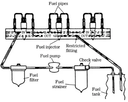
Most failures involve the fuel system. This system consists of three circuits, each operating at a different pressure as mentioned below:
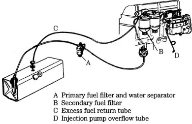
• Low-pressure circuit. This includes the tank strainer, in-tank pump (on many vehicles), water-fuel separator, filter(s), and lift pump. Pressures vary with the application, but rarely exceed 75 psi.
• High-pressure circuit. As shown in Figure 4-1, the high-pressure circuit connects the discharge side of the injector pump with the injectors. For many applications, the connecting plumbing takes the form of dedicated lines from pump to the individual injectors. A more modern
approach is to supply the injectors from a common manifold, or rail. The third alternative does away with the external high-pressure circuit by employing unit injectors (UIs). Each UI is a self-contained unit, with its own high-pressure pump operated by an engine-driven camshaft or, in the case of the Hydraulic Electronic Unit Injector (HEUI), by oil pressure. The unit pump system (UPS) is a hybrid, with each injector served by a dedicated pump plunger operating off the
engine camshaft. Plunger-to-injector lines are pressurized.
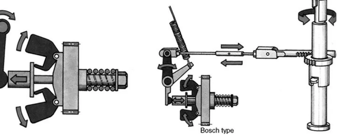
4-1 This drawing illustrates the high-pressure circuits for four modern fuel systems. From a mechanic’s point of view, the UI system has much to recommend it. High pressures are confined within the injector bodies and failures tend to be cylinder-specific. (Photo Bosch)
A mechanic has a duty to himself to know the pressures he is dealing with. Most, but not all, older-model engines had fuel systems that operated in the neighborhood of 6000–12,000 psi. But even at 6000 psi, fuel easily penetrates the skin (witness the speckled hands of old diesel mechanics) and often results in blood poisoning. Common-rail and other modern systems generate pressures on the order of 30,000 psi. Pressures of this magnitude cut to the bone and, if air bubbles are present, the fuel jets out like water from a hose.
connections. High-pressure fuel leaks may not be visible, but can be detected with as splatter on a piece of cardboard placed next to the connection.
Hydraulically actuated HEUI injectors shift the high-pressure regime to lube oil supplied at between 800 and 3300 psi, which is still a considerable pressure. These and other electronic
injectors (recognized by the presence of wires running to them) pose the risk of electroshock. Injector voltages and amperages can be lethal.
WARNING: Do not disconnect the wiring to electronic injectors while the engine is running.
For fuel to enter the cylinders, the h-p pump must generate enough pressure to unseat the injectors. Pop-off pressure, known more formally as NOP (nozzle opening pressure) or VOP (valve opening pressure), depends upon an unrestricted fuel supply. Air leaks or fuel blockages upstream of the pump, or failure of the pump itself can reduce delivery pressure below NOP. Electronic engine management systems keep close watch on delivery pressure and its effect on other variables, such as the concentration of oxygen in the exhaust. Low delivery pressure triggers one or more trouble codes.
Older, precomputer engines require a more proactive approach to determine if fuel is getting to the cylinders. One technique is to spray starting fluid into the air intake while cranking. If the engine starts, runs for few seconds and stalls, you can be reasonably confident that the problem lies in the fuel system.
CAUTION: Employ starting fluid with discretion. Glow plugs can ignite the fluid in the manifold and large amounts of starting fluid in the intake manifold or in the scavenging system on two-cycle engines can result in explosions powerful enough to break piston rings and bend connecting rods.
An alternative approach is to crank the engine over for a 20 or 30 seconds, and crack the fuel-supply line to one or more injectors. Fuel should be present. Note that this technique should be confined to older engines known to generate moderate fuel pressures of 6000 psi or so.
Bleeding