THE MICROSCOPE • Vol 57:3, pp 127-132 (2009)
Analysis of Carbon Nanotubes in Air
J.R. Millette, W.B. Hill and W.L. Turner Jr.
MVA Scientific Consultants*
S.M. Hays
Gobbell Hays Partners, Inc.**
KEYWORDS
Nanotubes, nanoparticles, airborne carbon nanotube (CNT), single-wall nanotube (SWNT), multiwall nanotube (MWNT), transmission electron microscopy (TEM), analytical electron microscopy (AEM), mixed cellulose ester membrane (MCE) filters, sampling cassettes, fullerene, R. Buckminster Fuller
ABSTRACT
Carbon nanotubes are extremely small particles composed of networks of carbon atoms formed into cyl-inders with diameters in the nanometer range. The re-sults of initial tests demonstrate that airborne carbon nanotubes can be collected successfully on membrane filters using standard air-monitoring cassettes. This paper presents the methodology for the analysis of car-bon nanotubes by transmission electron microscopy.
INTRODUCTION
No generally recognized standard methods for the collection of airborne carbon nanotubes (CNTs) cur-rently exist. Our laboratory and others (1) provide analyses for industrial facilities involved with produc-tion of, or manufacturing products with, CNTs. They monitor for airborne CNT using commercially avail-able mixed cellulose ester membrane (MCE) filters in air sampling cassettes. The collected particles are then analyzed by transmission electron microscopy (TEM) using sample preparation and analysis procedures similar to those used for TEM asbestos analysis.
The development of carbon nanotubes followed the discovery of “Bucky balls” or “fullerenes” that are closed carbon caged molecules with 60 carbon atoms. They are described in a 1985 Nature article entitled: “C-60 Buckminsterfullerene” (2) and named in honor of R. Buckminster Fuller, famous for his geodesic dome de-signs. Elongated “fullerenes” with aspect ratios greater than 20:1 were reported by Professor Sumio Iijima in 1991 (3) and termed simply, carbon nanotubes (CNTs). Carbon nanotubes are hexagonal networks of car-bon atoms that have been rolled up to make a seam-less cylinder. The ends of each cylinder are “capped” with half of a fullerene molecule. Figure 1 shows a TEM image of the cylindrical structure of single-wall nanotubes (SWNTs) that form the basis for multiwall nanotubes (MWNTs) (Figure 2). SWNT can have di-ameters in the range of 0.5 to 5 nm (4). MWNT diam-eters vary in size depending on the number of walls. Both SWNTs and MWNTs can have lengths from a few nanometers to several micrometers.
Nanotubes are 100 times stronger than steel of the same weight. They conduct heat better than diamond and conduct electricity better than copper. Currently, carbon nanotubes are used in a limited number of com-mercial products such as lightweight composites in sail boat masts, camera tripods, and sports equipment such as golf clubs, tennis rackets and baseball bats (Figure 3). However, because of the unique useful prop-erties of CNTs, many more products are in develop-ment. For example, the first CNT-based, flat-panel dis-play prototype was introduced by Motorola in 2005.
Figure 1. TEM image of single-walled carbon nanotubes.
Photomicrograph by Johanna DeCotis Photomicrograph by Johanna DeCotis
Figure 2. TEM image of multiwalled carbon nanotubes.
Figure 3. The label indicates the use of carbon nanotubes in this baseball bat.
two errors and suggest corrections in the article by Han et al. (1) that might cause confusion in a labora-tory trying to follow their technique. In the sampling section of their paper, Han and fellow authors state: “All samples were taken by drawing air through mixed cellulose ester filters in sampling cassettes (35 mm di-ameter, 0.8 μm nominal pores size, and 2-inch cowl) obtained from Environmetrics, Inc. (catalogue num-ber 20-31-0-1401, Charleston, SC).” The air cassettes with 2-inch cowls sold by Envirometrics were 25 mm in diameter, the usual standard diameter cassette size used in the asbestos monitoring industry. The
meth-ods section of the paper states: “The filter was coated with carbon and mounted onto carbon-coated nickel grids using chloroform vapor.”
Mixed cellulose ester (MCE) filters are not very soluble in chloroform. Therefore, chloroform is not used in the preparation of grids from MCE filters. The stan-dard methods involving the preparation of MCE fil-ters for TEM analysis call for the use of either acetone or dimethyl formamide (6-10). There is also no reason to mount the carbon-coated filters onto carbon-coated grids. After carbon coating, the filter can be placed on plain grids. Having two layers of carbon makes it more difficult to find the carbon nanotubes during analysis due to the loss of contrast.
The following is a presentation of the method cur-rently being used by MVA Scientific Consultants for the analysis of carbon nanotubes in air. The method can be used with either 0.8 μm or 0.45 μm pore size MCE filters; we prefer using the 0.45 μm filter, because it is the one specified in the TEM methods that involve analysis for small fibers (8-10).
MVA METHOD FOR ANALYSIS OF CARBON NANOTUBES IN AIR
Sample Collection
J.R. MILLETTE, W.B. HILL, S.M. HAYS and W.L. TURNER Jr.
cellulose nitrate) membrane filter of pore size 0.45 μm using a battery-powered (personal) or a high-volume (area) pump. The sample is collected with a 25 mm cassette with a 2-inch cowl in the open-face position (without the cassette end cap).
Sample Preparation
A portion of the cellulose ester filter is cut and placed on a glass microscope slide and the filter material is collapsed using acetone in a Jaffe washer. Using a vacuum evaporator, a thin film of carbon is deposited onto the filter surface. Small squares are cut from the filter and placed on TEM specimen grids. The filter me-dium is dissolved using dimethyl formamide (DMF) and acetone. This procedure encases the particles in a thin film of carbon between the grid openings with each particle in its original position as it was on the filter.
Sample Analysis
The samples are analyzed with analytical electron microscopy (AEM) using a Philips 420 or Philips 120 100 kV transmission electron microscope (TEM), equipped with Oxford energy dispersive x-ray analy-sis systems (EDS). In the TEM, nanotubes are identified and recorded in randomly selected grid openings. Iden-tification of nanotubes is based on morphological com-parison with reference nanotube materials.
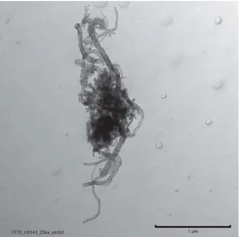
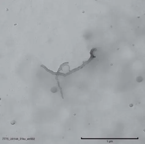
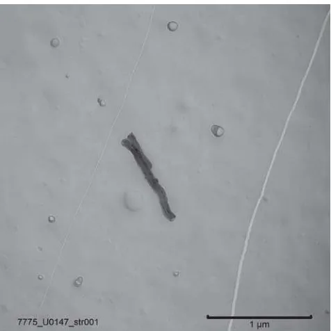
Figures 4-13 show images of multiwall carbon nanotubes. Elemental analysis showing that the
Figure 4. TEM image of airborne multiwall nanotubes collected on an MCE filter.
Figure 5. TEM image of airborne multiwall nanotubes collected on an MCE filter.
Figure 6. TEM image of airborne multiwall nanotubes collected on an MCE filter.
Figure 7. TEM image of airborne multiwall nanotubes collected on an MCE filter.
Figure 8. TEM image of airborne multiwall nanotubes collected on an MCE filter.
Figure 9. TEM image of airborne multiwall nanotubes collected on an MCE filter.
J.R. MILLETTE, W.B. HILL, S.M. HAYS and W.L. TURNER Jr.
area analyzed, the effective filter area and the volume of air collected.
DISCUSSION
In initial studies of the CNTs dispersed in liquids, no nanotubes were found in the filtrate liquid collected after filtration through 0.45 μm MCE filters. This sug-gested that nanotubes would not penetrate through 0.45 μm pore size MCE filters.
Initial studies of CNTs dispersed in air were per-formed in a glove bag with an aerosol produced by a technique using a vortex aerosolizer as described by Ku et al. (5). In the test, a 0.45 μm MCE filter was fitted into a 25 mm standard cassette with a 2-inch cowl in the open-face position. The outlet of this cassette was connected to the inlet of another standard 2-inch cowl cassette in the closed-face position (Figure 14). This second cassette was fitted with a 0.2 μm MCE filter, and because of the closed-face position, any break-through from the 0.45 μm filter would become concen-trated in a small, central spot on the 0.2 μm filter.
Three identical sampling trains were prepared. The aerosol challenge to the 0.45 μm filter was commercial MWNTs obtained from Sun Innovations, Inc., in Fre-mont, CA. The product is listed as 95 percent pure. The airborne concentration of MWNTs was estimated to be over 40,000 CNTs per cubic centimeter. No break-through CNTs were found on two of the 0.2 μm filters.
Figure 11. TEM image of airborne multiwall nanotubes collected on an MCE filter.
Figure 12. TEM image of airborne multiwall nanotubes collected on an MCE filter.
Figure 14. Arrangement of the 0.45 µm pore-size air filter
cassette (25 mm diameter with a 2-inch cowl) followed by the 0.2
µm pore-size filter cassette.
The analytical sensitivities of the two filter tests were 0.3 and 0.15 nanotube structures per cubic centimeter. The third filter test was inconclusive. On the third fil-ter, the level (two nanotubes) was not statistically dif-ferent from the level (one nanotube) found on one of the chamber test blank filters.
The MCE filters appear to be efficient in collecting all the carbon nanotubes. Although the CNTs have di-ameters in the nanometer range, they have lengths that are long — in some cases tens of micrometers long — and tend to curl and tangle together. Therefore, al-though the diameters are a hundred times smaller than the pore size of the filter, the curled and tangled CNTs are caught in the tortuous pathway membrane filter. Even if the CNTs are relatively straight, they are too long to navigate the twisting path through the sponge-like MCE filter.
While some research efforts continue on certain aspects of the method, preliminary data show that it provides a good index of the measure of exposure to airborne carbon nanotubes.
ACKNOWLEDGEMENTS
The authors would like to thank Brett Eason and Johanna DeCotis for their contributions to this re-search work.
REFERENCES
1. Han, J.H., Lee, E.J., So, K.P., Lee, Y.H., Bae, G.N., Lee, S.B., Ji, J.H., Cho, M.H., and Yu, I.J. “Monitoring Multiwalled Carbon Nanotube Exposure in Carbon Nanotube Research Facility.” Inhalation Toxicology, 20 (8), pp 741-749, 2008.
2. Kroto, H.W., Heath, J.R., O’Brien, S.C., Curl, R.F., and Smalley, R.E.”C 60: Buckminsterfullerene.” Nature, 318, pp 162-163, 1985.
3. Iijima, S. “Helical Microtubules of Graphitic Carbon.” Nature,354, p 56, 1991.
4. Kanzow, H., Bernier, P., and Ding, A. “Lower limit for single-wall carbon nanotube diameters from hy-drocarbons and fullerenes.” Applied Physics A: Materials Science & Processing, 74 (3), pp 411-414, 2002.
5. Ku, B.K., Emery, M.S., Maynard, A.D., Stolzenburg, M.R., and McMurry, P.H. “In Situ Struc-ture Characterization of Airborne Carbon Nanofibres by a Tandem Mobility — Mass Analysis.”
Nanotechnology, 17, pp 3613-3621, 2006.
6. Few, P. and Millette, J.R. “Filter Preparation for Particle Analysis by Transmission Electron Micros-copy.” TheMicroscope,56 (1), pp 3-11, 2008.
7. National Institute of Occupational Safety and Health, “Asbestos Fibers by Transmission Electron Microscopy (TEM) — Method 7402.” NIOSH Manual of
Analytical Methods, 4th ed.; U.S. Department of HHS,
NIOSH Publications, pp 94-126, 1994.
8. AHERA/U.S. Environmental Protection Agency. “Asbestos-Containing Materials in Schools, Final Rule and Notice - Appendix A to Subpart E, Interim Trans-mission Electron Microscopy Analytical Methods (40 CFR Part 763).” Federal Register, 52 (210), pp 41857-41894, 1987.
9. International Standards Organization. “ISO 10312, Ambient Air — Determination of Asbestos Fi-bres — Direct-transfer Transmission Electron Micros-copy Procedure,” 1995.