Security Lock with DTMF Polyphonic Tone Sensor
Abstract—Home automation (smart home) is a home that which it is equipped by a system for controlling and integrating electronic devices, such as lighting, home theather, CCTV (closed-circuit television), HVAC (heating, ventilation, and air conditioning), security locks of gates and doors, motion sensor, and etc. The purpose is to provide the improved simplicity, energy efficiency, security, and comfortability at home for the user benefits. Smart home can be easily controlled by a PC or laptop, tablet, or even smart phone. For example, smart phone could be integrated as a part of tone sensor system for security door lock automation. In this research work, the locking automation system using smart phone polyphonic tone sensor have been designed and implemented. A simple unlocking mechanism is explained as follows. The DTMF (Dual Tone Multi Frequency) module which has been programmed with Arduino was used to receive the signal from the polyphonic smart phone. After processing by Arduino Uno, then the driver will unlock the door. In three seconds, it will lock again. The security system like in the ATM (automated teller machine), the working range sensitivity of the system, and the amount of password digits are some limitations of this work, which could be better improved in the near future.
Keywords—Automation; Arduino Uno; DTMF module; sensor; security door lock
I. INTRODUCTION
Sound sensor is the device that has function to detect or sense something based on the sound environment. One of examples is the ring tone sensor. Just play the ring tone until it ends and the switch will be automatically on/off.
Home automation (smart home) is a home that which it is equipped by a system for controlling and integrating electronic devices, such as lighting, home theather, CCTV (closed-circuit television), HVAC (heating, ventilation, and air conditioning), security locks of gates and doors, motion sensor, and etc. The purpose is to provide the improved simplicity, energy efficiency, security, and comfortability at home for the user benefits. With a smart home, all devices and appliances can be connected so they can communicate with each other and with us as human. Smart home can be easily controlled by a PC or laptop, tablet, or even smart phone.
In this paper, the design of the locking automation system using polyphonic tone sensor has been implemented. The rest of this paper is organized as follows. Section II gives the design concept and implementation of this polyphonic tone sensor device. Section III shows the experimental results and brief discussion analysis. Lastly, Section IV gives conclusions.
II. DESIGNCONCEPTANDIMPLEMENTATION
In this section, we are intended to clearly and efficiently describe the hardware and software materials that are needed to design and implement this tone sensor device:
A. DTMF (Dual Tone Multi Frequency)
DTMF [1] is a basis for voice communications control and is widely used worldwide in modern telephony to dial numbers. A DTMF signal is consisted of the sum of two sinusoidal frequencies (high and low groups), frequencies with smooth repetitive oscillations. Those frequencies were chosen to prevent any harmonics from being incorrectly detected by the receiver as some other DTMF frequency. The frequency of each dial number is shown in Fig. 1.
The transmitter of a DTMF signal simultaneously sends one frequency from the high-group and one frequency from the low-group. For example, sending 1209 Hz and 770 Hz indicates that the "4" digit (number) is being sent.
The signal generated by a DTMF encoder is a direct algebraic summation (in real-time) of the amplitudes of two sine (or cosine) waves with different frequencies [2].
At transmitter, the maximum signal strength of a pair of tones must not exceed +1 dBm, and the minimum signal strength is -10.5 dBm for the low-group frequencies while for the high-group frequencies is -8.5 dBm.
DTMF module (Fig. 2) by DFRobot is used as one of the main parts in of this device [3]. This module already has sound sensor that is suitable for DTMF tone as it was programmed. There are three main specifications of this DTMF module (the dimension is 37 mm x 37 mm x 9 mm): (1) microphone integrated for testing with LED that shows the audio signal strength, (2) audio socket for application, and (3) potentiometer on board to regulate the receiving volume.
B. Arduino Uno
Arduino Uno is a microcontroller board based on the ATMega328. It has 14 digital input/output pins, 6 analog inputs, a 16 MHz ceramic resonator, a USB connection, a power jack, an ICSP header, and a reset button.
Arduino Uno contains everything we need to support the microcontroller, by simply connecting it to a computer with USB cable or power it with AC-to-DC adapter or battery to get started. Fig. 3. and Table I show the module and detail specs of Arduino Uno we used in this sensor, respectively.
2015 International Conference on Automation, Cognitive Science, Optics, Micro Electro-Mechanical System, and Information Technology (ICACOMIT), Bandung, Indonesia, October 29–30, 2015
Fig. 1. DTMF pad shows the low and high group frequencies.
Fig. 2. DTMF module.
Figure 3. Arduino Uno module.
C. 2-Channel Relay Module
This relay module (Fig. 4) lets the microcontroller like Arduino to control digital outputs that have higher loads, for example like AC or DC motors, lightbulb, solenoid, etc. This module is designed to be integrated with 2 relays. So, it is capable to control 2 relays. The relay output state is indicated by a light-emitting diode (LED). Detail features of this relay module as follow [4]: 5V 2-channel relay interface board, where each one needs 15-20 mA driver current; equipped with high-current relay: AC 250V-10A and DC 30V-10A; standard interface that can be controlled directly by microcontroller; and an indication LED for relay output status.
TABLE I. Arduino Uno detail specifications.
Item Specs Item Unit
Microcontroller ATMega328
Operating Voltage 5 V
Input Voltage (recommended) 7-12 V
Input Voltage (limits) 6-20 V
Digital I/O Pins 14
Analog Input Pins 6
DC Current per I/O Pin 40 mA
DC Current for 3.3 V 50 mA
Flash Memory 32 KB
SRAM 2 KB
EEPROM 1 KB
Clock Speed 16 MHz
Length 68.6 mm
Width 53.4 mm
Weight 25 gr
Fig. 4. 2-Channel relay module.
D. Buzzer
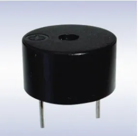
Buzzer is the audio signalling device. It may be in the form of mechanical, electromechanical, or piezoelectric systems. The function is to indicate the input and the output. So, with the sound of the buzzer we can know whether the input and the output have been succesfully processed. Typical uses of buzzers and beepers include alarm devices, timers, and confirmation of user input such as by a mouse click or keystroke. Fig. 5 is the figure of 12 mm black magnetic electronic buzzer device active 5V, from Noryl Housing.
Fig.6. Circuit of security lock with DTMF polyphonic tone sensor.
E. Operation Mechanism
After all, this subsection provides a brief description of how this sensor works as pictured in Fig. 6. Aforementioned, this device has two main parts: the first part is the DTMF module that reads the data inserted through the smart phone DTMF tone. The second part is an Arduino programming that processes the information through channel-relay module. So, after the smart phone input the 4-digit number (code) that has been saved in Arduino through the DTMF module, then the module will read the data and pass it again through Arduino Uno. The Arduino Uno will process the information and send it to the solenoid through the relay module to unlock the door. The block diagram of the whole process is described in Fig. 7.
III. EXPERIMENTALRESULTS
This section will describe the results of the experiment. The first is when we input the default password at standby mode, which is 1, 2, 3, and 4. This default password will be entered as the unlocking mode. The serial input is shown in Fig. 8 and the door (solenoid) will be unlocked. So, when the input password is correct, the buzzer will beep once, then the relay will be on and the solenoid (door) will be opened in 3 seconds, after that it will be closed again.
A. Changing the password
To change the password, we press the *button that will be shown by -2 number in the serial monitor and the buzzer will produce sound three times with 100 ms delay. Then, input the old password which is 4-digits. After input the old one, the buzzer will beep once as an indicator that we must enter the new password. After put the new one, the solenoid (door) will be opened like when we put the correct password and the device will start again in the standby mode. It is shown in the serial monitor of Fig. 9.
B. Enter the wrong password
But, when we put the wrong password, the buzzer will beep twice. The description in the serial monitor for entering the wrong password is shown in Fig. 10. And Table II shows the range-testing experimental results which are conducted by the authors.
Fig. 7. Block diagram of the process from data input to unlock the door.
Fig. 8. Default password input in the serial monitor.
Fig. 9. Changing the password.
TABLE II. Range-testing results.
Distance Result Comment
1 cm Good Fine
5 cm Good Fine
10 cm Good Fine
>10 cm No response Not connected
C. Brief Discussion Analysis
From the measurement data at Table II, it is concluded that the sensitivity of this sensor device is low. We can see that the working-range of this system is limited to only 10 cm distance. It may need additional circuits to make the sound can be detected in further distance for future improvements.
Besides, the security system in this sensor device has not been applied yet. For example, like the security system in the ATM (automated teller machine), which has blocking feature, where if we put the wrong password three times, the account will be blocked until it can be unlocked again after 24 hours since the blocking time.
However, this tone sensor device has advantage. It can handle the noise surrounding the area due to the function of the DTMF module. This sound sensor is match only for DTMF tone, so other noises (sounds) will be omitted by this tone sensor device.
IV. CONCLUSIONS
In this paper, the security lock with DTMF polyphonic tone sensor using Arduino software programming has been
proposed and implemented. Of course, the knowledge of Arduino coding is an important (integral) part to make this sensor device works.
This new locking way is expected to be used at home (as part of the smart home automation and system). Also, it can be applied in such many other places like schools, restaurants, residences, and public places to substitute the old locking way. Actually, this research work still needs some improvements in the near future. For the next, the freedom to choose the number of digits (how many digits the users want) can be improved. The security system which we were discussed in subsection C of section III also can be applied. And last but not least, the sensitivity of the system also can be improved by adding some additional circuits, so the sound could be detected from far away (more distance).
ACKNOWLEDGMENT
The authors thank to Aziz, for his teaching and explanation of the Arduino coding that was used in this research work.
REFERENCES
[1] F. Durda IV, “Dual Tone Multi-Frequency (Touch-Tone®) Reference,” 1995.
[2] Pascal DORSTER (TI), “Sine, Cosine on the TMS320C2xx”, Application Report, Texas Instruments Inc., 1996.
[3] DTMF Module (Arduino Gadgeteer Compatible) Datasheet and Specifications by DFRobot, 1995.