European Association for the Development of
Renewable Energy, Environment and
Power Quality
RENEWABLE ENERGY & POWER
QUALITY JOURNAL
RE&PQJ-7, ISSN 2172-038X
Renewable Energy & Power Quality Journal
No.7, April 2009
ISSN 2172-038X
RE&PQJ-7 EDITORIAL COMMITTEE
Manuel Pérez Donsión (Main Editor) Ramón Bargalló Perpiña
Manuel Burgos Payán Debora Coll Mayor Mario Mañana Canteli
Mariano Sanz Badía
RE&PQJ-7 SCIENTIFIC COMMITTEE
Alexandru, Catalin (Romania) Andrada Gascón, P. (Spain) Andras, Dan (Hungary) Arcega Solsona, F. (Spain) Arnaltes Gómez, S. (Spain) Balestrino, Aldo (Italy)
Barajas Forero, C.L. (Colombia) Bargallo Perpiña, R. (Spain) Bendl, Jiri (Czech Republic) Bitzer, Berthold (Germany) Boccaletti, Chiara (Italy) Burgos Payan, M. (Spain) Brslica, Vit (Czech Republic) Capolino, G.A. (France) Cortez, Liliana (México) Driesen, Johan (Belgium) Donsión, M.P. (Spain) Duran, M. (Spain)
Eguiluz Morán,L.I. (Spain) Ertan, H.B. (Turkey)
Fernández Cabanas, M. (Spain) Figueiredo, J.M.G. (Portugal) Flores, Antonio (Portugal) Fraile Mora, Jesús (Spain) Funabashi, Toshihisa (Japan) Gharehpetian, G.B. (Iran) Ghita, Constantin (Romania) Göl, Ozdemir (Australia) Güemes Alonso, J.A. (Spain) Hermoso Alameda,B. (Spain) Iwaszkiewicz, J. (Poland) Jokinen, T. (Finland)
Kádár Péter (Hungary) Kladas, A. (Greece)
Klima, Jiri (Czech Republic) Lemos Antunes, C. (Portugal) Levi, Emil (U.K.)
Llombart Estopiñan, A. (Spain) Machado e Moura,A. (Portugal) Mañana-Canteli, M. (Spain) Martinez, André (France) Narsimhulu, Sanke (India) Niememan, Asco (Finland) Petkovska, L. (Macedonia) Predescu, Mihai (Romania) Redondo Gil, C. (Spain) Ribeiro, Hugo (Portugal) Robyns Benoit (France) Roger Folch, J. (Spain) Rusek, Jan (Poland) Saadate, S. (France)
257 Artificial intelligence techniques for controlling PV-wind powered rural zone in Egypt
Hanaa M.Fargli (1), Faten H. Fahmy (1), Mohamed A. H.EL- Sayed (2)
(1). Electronics Research Institute, National Research Center building, Cairo, Egypt (2). Center of Energy Studies, University of Trinidad and Tobago
259 Centralized normalization of harmonic voltages in the supply network for traction substations
L.I. Kovernikova
The Siberia Branch of the Russian Academy of Sciences. Energy Systems Institute. Russia
260 Analysis and NN-based control of doubly fed induction generator in wind power generation
Orlando Manuel Soares (1), Henrique Nuno Gonçalves (2), António Pina Martins (2), Adriano da Silva Carvalho (2)
(1). Escola Superior de Tecnlogia e de Gestão. Instituto Politécnico de Bragança. Portugal (2). Faculdade de Engenharia da Universidade do Porto. Portugal
262 Voltage measurement errors as a result of multiple VT groundings
F. Uriondo (1), G. Aguirre (1), J.R. Hernández (1), J.M. García (2)
(1). Department of Electrical Engineering. E.S.I. Bilbao. University of the Basque Country. Spain (2). INGETEAM T&D. Spain
264 High power fuel cell simulator using an unity active power factor rectifier
J.C. Alfonso-Gil (1), J.J. Vague Cardona (2), F.J. Gimeno- Sales (3), S. Seguí- Chilet (4), S. Orts Grau (5), N. Muñoz- Galeano (6)
(1-5). Department of Electronic Engineering. Universidad Politécnica de Valencia. Spain (6). University of Antioquia, Medellín. Colombia
265 Improved control of current controlled grid connected inverters in adjustable speed power energies
J.J. Vague Cardona (1), J.C.Alfonso Gil (1), F.J. Gimeno Sales (1), S. Segui- Chilet (1), S. Orts Grau (1), N. Muñoz Galeano (2)
(1). Department of Electronics Engineering. Universidad Politécnica de Valencia. Spain (2). Department of Electrical Engineering. University of Antioquia. Medellín, Colombia
268 Identification of photovoltaic array model parameters by robust linear regression methods
Maria Carmela Di Piazza, Antonella Ragusa, Gianpaolo Vitale
Consiglio Nazionale della Ricerche. Istituto di Studi sui Sistemi Intelligenti per l´Automazione (ISSIA). Palermo. Italy
270 Evaluation of different methods for voltage sag source detection based on positive-sequence components
Boštjan Polajžer, Gorazd Štumberger, Drago Dolinar
University of Maribor. Faculty of Electrical Engineering and Computer Science. Maribor, Slovenia
273 Measurement and calculation of harmonics in distribution power system with connected small co-generation facility Etan
Ana Tomasovic (1), Mate Lasic (1), Božidar Filipovic-Grcic (2) (1). Koncar Electrical Engineering Institute.Croatia
Renewable Energy & Power Quality Journal
No.7, April 2009
ISSN 2172-038X
529 Fault detection in the manufacturing process of form-wound coils by means of dissipation factor and hipotesis
M.G. Melero, M.F. Cabanas, C.H. Rojas, J. Norniella, F. Pedrayes, J.M. Barrera Department of Electric Engineering. University of Oviedo, Spain
530 Analysis of methodologies for the economical evaluation of power quality
D. Coll-Mayor (1), J. Pardo (2), M. Pérez Donsión (3)
(1). Department of Physics, University of Balearic Islands, Palma de Mallorca (Spain) (2). Department of Industrial Organization, ETSII, Vigo University. Spain
(3). Department of Electrical Engineering, ETSII, Vigo University.Spain
531 Pumped storage hydro plant model for educational purpose
Péter Kádar
Budapest Tech, Dept. of Power Systems. Budapest, Hungary
532 Influence of slot opening width and rotor pole radius on the torque of PMSM
J.A. Güemes (1), P.M. García (2), A.M. Iraolagoitia (1), J.J. Ugartemendia (2)
(1). Department of Electrical Engineering. E.U.I.T.I. University of the Basque Country. Bilbao. Spain (2). Department of Electrical Engineering. Escuela Universitaria Politécnica. University of the Basque Country. San Sebastian. Spain
534 Predictable impact of lighting control on the energy consumption of a building through computational simulation
H. Bernardo (1,3), S. Leitão (2), L. Neves (1,3), P. Amaral (1,3)
(1). Departmento of Electrical Engineering, School of Technology and Management, Potytechnic Institute of Leiria, Portugal
(2). Department of Engineering, University of Trás-os-Montes and Alto Douro. Portugal (3). Institute for Systems and Computer Engineering at Coimbra, Portugal.
P1 Harmonics in Power Systems
J.L. Hernández (1), M.A. Castro (2), J. Carpio (2), A. Colmenar (2)
(1) Department of Electricity. IES La Laboral de La Laguna. Avda. Lora y Tamayo, 2. La Laguna. Tenerife.
Analysis and NN-Based Control of Doubly Fed Induction Generator in Wind
Power Generation
Orlando Manuel Soares1, Henrique Nuno Gonçalves2, António Pina Martins2 and Adriano Silva Carvalho2
1
Escola Superior de Tecnologia e de Gestão Instituto Politécnico de Bragança
Campus de Santa Apolónia, 5301-857 Bragança, Portugal E-mail: [email protected]
2
Faculdade de Engenharia da Universidade do Porto Rua Dr. Roberto Frias, 4200-465 Porto, Portugal E-mail: [email protected], [email protected] and [email protected]
Abstract.
With the increasing size of wind power generation it is required to perform power system stability analysis that uses dynamic wind generator models.In this paper are presented all the wind power system components, including the turbine, the generator, the power electronic converter and controllers. The aim is to study the Doubly Fed Induction Generator (DFIG) operation and its connection to the power system, either during normal operation or during transient grid fault events.
Two different control system design technologies are present, the first is performed by standard PI controllers and the second is based on artificial neural networks.
Keywords
Wind power generation, Simulation, Control, Neural networks, Doubly fed induction generator.
1.
Introduction
The impact of wind farms on the power systems has mainly been on the voltage of the local feeder and the local substation. As the size of the wind farms increases on as well as the level of penetration into power system, the impact on the power system is not only local but has influence on a much larger part of the system including the unit commitment and dispatch.
Present growth and related installed power level make necessary to develop wind farm control capabilities and strategies that had features equivalent to conventional power plants. These features include capabilities to control the output power of the total wind farm, control of the reactive power and robustness to faults in the grid. This will enable wind power plants to be included as active components of the power supply system, [1]-[2]. The purpose of the control system is to manage the safe, automatic operation of the turbine, within a framework of optimising generated power. This reduces operating
costs, provides consistent dynamic response and improved product quality, and helps to ensure safety by maximizing the capture of the wind energy due to minimization of turbine loads.
Many wind power turbines with related control strategies were developed by so many authors. These strategies include fixed and variable wind turbines with the same purpose of extracting the maximum wind power with the best quality service.
This paper describes wind generation models for operation within power system in order to perform stability analysis and turbine control to maximize the power generated with the lowest impact on the grid voltage and frequency during normal operation and under several disturbances, such as a transmission line earth fault. The discussed methods considers wind turbines based on induction generator and a grid-connected converter with constant or variable blade angle applied to variable speed wind turbines. The study is performed within the multiple technologies design tool Matlab/Simulink, [3].
Two power control techniques were used: PI controllers and artificial neural networks. The dynamic control joins different strategies that will ensure better stability and power regulation generated by the wind turbine. Those strategies with intelligent control techniques, such as artificial neural networks, allow the increase of robustness, performance, capacity and flexibility.
2.
The Control Structure Model
A. Turbine and Drive-Train Subsystem
The aerodynamic model is appropriate to a wind power generating system turbine that tracks a prescribed torque-speed profile, function of the power to be delivered. Variable speed operation is introduced to gain efficiency in generating power. The torque-velocity wind turbine characteristic allows the establishment of several possible wind turbine operation control strategies. This means that
CP can be calculated as by control of the aerodynamic
model and used to determine the aerodynamic power Pae, [1]-[2].
The mechanical model was selected with emphasis to include only parts of the dynamic structure, that are important to the interaction with grid, i.e. which influence significantly on the fluctuations of the power. Thus, only the drive train is considered in the first place because this part of the wind turbine has the most significant influence on the power fluctuations. The state space equations can be obtained from the mechanical model to perform the drive train simulation, [1]-[2].
B. Doubly Fed Induction Generator
The induction generator model adopted in this work is the qd0 stationary rotating reference frame model because it is more appropriate to simulate induction machine transients. The mathematical transformation abc to qd0 facilitates the computation of the transient solution of the induction generator model by transforming the differential equations with time-varying inductances to differential equations with constant inductances, [4]-[7].
⎪
The study of the induction generator reveals the stability and performance in transient condition of the induction generator to mechanical input torque when connecting the doubly fed induction generator to the power system.
C. Power Electronics Converters
Using a PWM back-to-back converter the voltage fluctuations, frequency, and output power from the wind turbine can be controlled. The converter takes control on the fluctuating non-grid frequency output power of the induction generator to a DC voltage level that will be injected through a PWM-converter into a three-phase grid frequency power, [8]-[9].
The electronic power converter used was a back-to-back converter witch allows to inject and get current from the rotor with current flow in both sides, [4], [6].
3.
The PI Control Structure Model
It is intended to control the power delivered by each generator in a way to optimize the operation of the wind park with propose to deliver the maximum active power to the grid in conditions of quality of service and safety. Also it intends to control the reactive power flow according to specified needs and dispatch. Thus, an adequate control strategy cans, [9]:
1) Control the active power supplied by the turbine in order to optimize the operating point;
2) Limit the active power in the case of high wind speed;
3) Control the interchange of the reactive power between the generator and the grid, especially in the case of weak grids, where voltage fluctuations can occur;
4) Guarantee the quality of service of the wind park, namely the grid voltage;
5) Minimize the exploration and maintenance costs of the wind park.
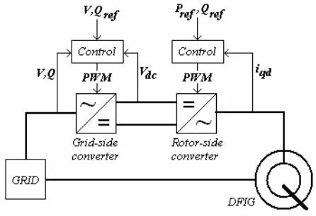
A typical configuration is illustrated in Figure 1 and it is based on a DFIG.
Fig. 1. General DFIG control structure.
The aim of the rotor- side converter is the independent control of the active power and reactive power witch are controlled, not directly, but by the control of the rotor current. The aim of the grid-side converter is to keep constant the DC voltage in the intermediate capacitor in order to guarantee an operation of the converter with power factor equal to one guaranteeing only the exchange of reactive power through the stator, [9].
In Figure 1, Pref is the optimal value for the active power and is gotten from the characteristic of the turbine for the speed of rotation of the rotor and the pitch angle. The value of Qref is defined in a way to keep the voltage stable at the grid connection point.
with the position of the voltages of the stator or grid. This allows independent control of the active and the reactive power between the converter and the grid.
For the internal control loop it is necessary to design the PI controllers’ functions, which are obtained by application of the Laplace transform of (5) that represents the grid-side converter voltages in its dq components, [9].
⎪
Using the Laplace transformation
(
)
Assigning in the previous equations:
(
)
the following equations can be used to design the current control loops, [9]:
sL be obtained by:
⎩
These reference values are the inputs used in the PWM converter in order to guarantee the DC voltage level and required power factor.
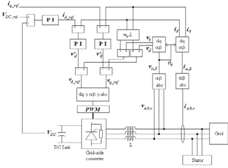
The grid-side converter control diagram is shown in Figure 2, for which normalized design techniques can be applied.
B. Rotor-Side Converter Control
The control of the induction generator rotor is carried through in a synchronous rotating dq referential, with the d-axis aligned with the stator flux position. In this way decoupling between the electromagnetic torque and rotor the magnetizing current can be obtained. The PWM converter acts on the generator rotor and the control is done by means of the signals of the rotor and the stator currents, the stator voltage and the rotor position.
Figure 3 presents the controller of the rotor-side converter control diagram. The control design of the
Fig. 2. Grid-side converter controller diagram.
Fig. 3. Rotor-side converter controller diagram.
⎪
i are applied to the PI controller
to obtain the voltages v and dr r q
v , respectively. To compensate the control are added the decoupling terms to the previous equations in order to get the reference voltages vdr_ref and
4.
The NN Controller Structure Model
The new control system will use a NN to substitute some blocks of the traditional system of vector control, [10]-[12].
neural networks to be used in the control system alternatively to the one based on PI controllers, with the intention of efficiently extract the wind energy, i.e. to be able to extract the maximum power of the turbine during some situations of functioning through the estimation of the control parameters for the grid-side and rotor-side converters.
A. NN Controllers Architecture
The learning algorithm updates the values of the weights and bias values according to the descendent gradient with momentum factor and adaptive learning ratio, also indicated in Table I, as well as the activation functions used in each layer and respective parameter, [13].
The sampling frequency is 20 kHz. The numbers of time delays used in each layer of the neural network had been adjusted as resulted of several simulations.
The used learning input-output pairs were generated by several system simulations and contemplate operation points with the machine operating in a zone below the synchronism speed, where active power is supplied to the rotor of the machine; in a zone near the synchronism speed, where the active power flow in the rotor of the machine is practically null; and a zone above the synchronism speed, where the machine supplies active power to the grid through the stator and the rotor.
TABLE I. - NN layers parameters.
1st Hidden Layer
2nd Hidden Layer
Output Layer Activation function - ϕ Symmetric
sigmoidal
Symmetric
sigmoidal Linear
Parameter - γ 2,0 2,0 -
Parameter - a 2,0 2,0 - Parameter - c -1,0 -1,0 - Learning coefficient - η 0,05
Momentum - α 0,9
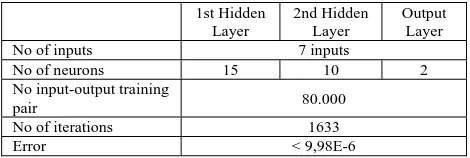
For the rotor-side controller was used a 7-15-10-2 neural network configuration as is shown in Table II, where the inputs are the stator and rotor currents, the rotor-side reference currents and the rotor angular speed, and the outputs are the reference voltages to control the rotor-side converter.
For the grid-side controller was used a 7-18-8-2 neural network configuration as is shown in Table III, where the inputs are the stator voltages and currents, the grid-side reference currents, and the angular frequency ωs, and the outputs are the reference voltages to control the rotor-side converter.
TABLE II. - NN architecture and training parameters of the rotor-side controller.
1st Hidden Layer
2nd Hidden Layer
Output Layer No of inputs 7 inputs
No of neurons 15 10 2
No input-output training
pair 80.000
No of iterations 1633
Error < 9,98E-6
TABLE III. - NN architecture and training parameters of the grid-side controller.
1st Hidden Layer
2nd Hidden Layer
Output Layer No of inputs 7 inputs
No of neurons 18 8 2
No input-output
training pair 80.000 No of iterations 1313
Error < 9,99E-6
4. Results
A. Reactive Power Control
In this simulation it is intended to vary the reference value of the reactive power in two steps, a first positive of 0.2 p.u., and the other equal to -0,4 p.u. Figures 4 and 5 show the signals of the reference voltages generated by the current regulators for the controllers of the grid-side and the rotor-side converters with NN (in the blue colour) and PIs (in the green colour).
Fig. 4. Reference grid-side voltage vdq, due to reactive power
control.
Fig. 5. Reference rotor-side voltage vdq, due to reactive power
control.
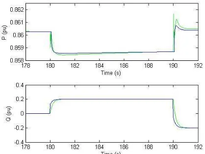
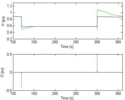
Fig. 6. Active power and reactive power, due to reactive power control.
It can be verified that the NN response is more desirable; it has a faster response to reach the stationary regimen, namely the value of the active power after 190 seconds.
B. Active Power Control
In a second simulation it is intended to verify the system response due to a variation of the active power flow, obtained through a variation in the quadrature component of the rotor current. This variation consisted in applying a negative pulse of amplitude equal to 0,2 p.u. The reference voltage signals for the controllers of the grid-side and rotor-grid-side converters have been registered in Figures 7 and 8, and the power flows in Figure 9.
Also in this situation, the maximum difference verified between the two control types is less than 0.5%, as in the previous case. The NNs present, generally, transients of lesser amplitude and greater speed to reach the steady-state condition. This behaviour is also verified in the main electric and mechanical variables.
Fig. 7. Reference grid-side voltage vdq, due active power
control.
Fig. 8. Reference rotor-side voltage vdq, due to active power
control.
Fig. 9. Active power and reactive power, due to active power control.
C. Phase-to-Earth Fault
A phase-to-earth fault in a line of the electrical network located near the wind park occurred at t=180 s with a duration of 180 ms. The fault impedance was 1 mΩ. Figures 10 and 11 show again the signals of the reference voltages used to control the stator-side and rotor-side converters, respectively, with NNs (in the blue colour) and PIs (in the green colour).
Fig. 10. Reference grid-side voltage vdq, due to a phase-to-earth
During the fault period, it was verified that the NNs response presents better results than the system using PI controllers; beside the peaks already related previously in the transitions, they present a lesser ripple. It is important to relate that in the direct component of the stator voltage with PI controllers the peaks can reach about 1,7 p.u. and that can cause some unwanted effects in the electronic devices used in the converters.
Fig. 11. Reference rotor-side voltage vdq, due to a phase-to-earth
fault.
In Figure 12 it can be verified that the disturbances caused in the active power and reactive power delivered to the grid are smoother with the use of the NNs.
Fig. 12. Active power and reactive power, due to a phase-to-earth fault.
4. Conclusion
The NN-based system that estimates the control parameters of the generator shown satisfactory characteristics, as was verified in the presented results.
Some differences in the controllers responses using neural networks can be noticed, namely three positive and advantageous aspects: transient regimes present smaller overshoots, or absence of them in some cases, what corresponds to less severe transitions; a faster response, i.e. the system retakes the permanent regimen in lesser time; and smaller oscillatory behaviour.
It was demonstrated that the reference signals for the grid-side and rotor-side converters of the DFIG can be obtained using control systems based in NNs. These can substitute most of the blocks of a conventional control system, and with the referred advantages.
References
[1] J. F. Walker, N. Jenkins, “Wind Energy Technology”, John Wiley & Sons, Ltd, 1997.
[2] T. Ackermann, "Wind Power in Power Systems", John Wiley & Sons, Ltd, England, 2005.
[3] C. Ong, “Dynamic Simulation of Electric Machinery”, Prentice Hall, 1998.
[4] A. Tapia, G. Tapia, J. X. Ostolaza, J. R. Saenz, R. Criado, J. L. Berasategui, "Reactive power control of a wind farm made up with doubly fed induction generators”, (I) and (II), IEEE Porto
Power Tech Conference, 2001.
[5] J. G. Slootweg, H. Polinder, W. L. Kling, "Initialization of wind turbine models in power system dynamics simulations", IEEE
Porto Power Tech Conference, 2001.
[6] A. Tapia, G. Tapia, X. Ostolaza, E. Fernández, J. R. Saenz, "Modeling and dynamic regulation of a wind farm", VII IEEE
International Power Electronics Congress, CIEP 2000, pp.
293-297, Acapulco, Mexico, 2000.
[7] J. L. Rodríguez-Amenedo, S. Arnalte, J. C. Burgos, "Automatic generation control of a wind farm with variable speed wind turbines", IEEE Transactions on Energy Conversion, vol. 17, no 2, pp. 279-284, 2002.
[8] J. G. Slootweg, H. Polinder, W.L. Kling, “Dynamic modeling of a wind turbine with direct drive synchronous generator and back to back voltage source converter and its controls”, European Wind
Energy Conference and Exhibition, Copenhagen, Denmark, July ,
2001.
[9] R. Pena, J. C. Clare, G. M. Asher, “Doubly fed induction generator using back-to-back PWM converters and its application to variable-speed wind-energy generation”, IEE Proc.-Elect.
Power Appl., vol. 143, no 3, May 1996.
[10] S. Haykin, “Neural Networks. A Comprehensive Foundation”, 2nd Edition, Prentice Hall, 1999.
[11] M. G. Simões, B. K. Bose, “Neural network based estimation of feedback signals for vector controlled induction motor drives”,
IEEE Transactions on Industry Applications, vol. 31, no 3, pp.
620-629, May-June 1995.
[12] F. M. de Azevedo, L. M. Brasil, R. C. L. de Oliveira, “Redes
Neurais, com Aplicações em Controle e em Sistemas Especialistas”, Florianópolis: Bookstore, 2000.
[13] H. Demuth, M. Beale, “Neural Network Toolbox for use with