DIRECT GEOREFERENCING ON SMALL UNMANNED AERIAL
PLATFORMS FOR IMPROVED RELIABILITY AND ACCURACY OF MAPPING
WITHOUT THE NEED FOR GROUND CONTROL POINTS
O. Mian a, J. Lutes a, G. Lipa a, J. J. Hutton a, E. Gavelle b S. Borghinic* a
Applanix Corporation, 85 Leek Crescent, Richmond Hill, ON, LB3 3B3 - (omian, jlutes, glipa, jhutton)@applanix.com b
Avyon, 137 Loyola-Schmidt Ave, Vaudreuil-Dorion, QC, J7V 8P2 - erwan@avyon.com c
Flyterra, 570 Chemin de l’aeroport, Alma (Qc), G8B 5V2, Canada - seb.borghini@flyterra.com
UAV-g 2015
KEY WORDS: Unmanned Aerial Vehicle, UAV, Direct Georeferencing, GNSS, Inertial, Mapping, Photogrammetry
ABSTRACT:
This paper presents results from a Direct Mapping Solution (DMS) comprised of an Applanix APX-15 UAV GNSS-Inertial system integrated with a Sony a7R camera to produce highly accurate ortho-rectified imagery without Ground Control Points on a Microdrones md4-1000 platform. A 55 millimeter Nikkor f/1.8 lens was mounted on the Sony a7R and the camera was then focused and calibrated terrestrially using the Applanix camera calibration facility, and then integrated with the APX-15 UAV GNSS-Inertial system using a custom mount specifically designed for UAV applications.
In July 2015, Applanix and Avyon carried out a test flight of this system. The goal of the test flight was to assess the performance of DMS APX-15 UAV direct georeferencing system on the md4-1000. The area mapped during the test was a 250 x 300 meter block in a rural setting in Ontario, Canada. Several ground control points are distributed within the test area. The test included 8 North-South lines and 1 cross strip flown at 80 meters AGL, resulting in a ~1 centimeter Ground Sample Distance (GSD).
Map products were generated from the test flight using Direct Georeferencing, and then compared for accuracy against the known positions of ground control points in the test area. The GNSS-Inertial data collected by the APX-15 UAV was post-processed in Single Base mode, using a base station located in the project area via POSPac UAV. The base-station’s position was precisely determined by processing a 12-hour session using the CSRS-PPP Post Processing service. The ground control points were surveyed in using differential GNSS post-processing techniques with respect to the base-station.
* Corresponding author
1. INTRODUCTION
1.1 Concepts and Benefits of Direct Georeferencing for Airborne Mapping
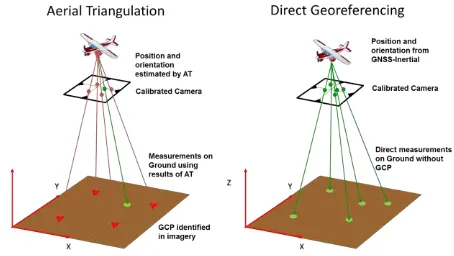
Direct Georeferencing (DG) of airborne sensor data as an alternative or complement to Aerial Triangulation (AT) is a method that first appeared commercially in the mid-1990s and has since evolved into a standard for airborne mapping (Hutton et al., 2005). As the term implies, Direct Georeferencing is the direct measurement of the position and orientation of an airborne mapping sensor such as a camera or laser scanner so that each pixel or range can be georeferenced to the Earth without the need for ground information collected in the field (Figure 1). This is achieved using data collected from Global Navigation Satellite Systems (GNSS) integrated with measurements from inertial sensors that directly attached to the mapping sensor. The data collected from the airborne GNSS and inertial sensors are processed in real-time and in post-mission along with data collected from a single or network of GNSS reference stations to produce precise measurements of
the sensor position and orientation exactly at the time of exposure or scan (Mostafa et al., 2001). Accuracies are typically at the centimeter level for position and can be in the milli-degrees range for orientation.
Figure 1: Direct Georeferencing Concept versus Aerial Triangulation
The benefits of Direct Georeferencing versus traditional AT for photogrammetric applications have been well studied (Ip et al., 2004), and can be summarized as follows:
Large cost savings through reduction or elimination of need to survey GCPs in the field
Improved collection efficiency by reducing or eliminating sidelap requirements resulting in fewer flight lines per area Improved point matching efficiency and adjustment accuracy when used with AT in an Integrated Sensor Orientation (ISO) approach
Ability to map in remote locations
Ability to map in real-time for disaster response applications
1.2 Challenges on Unmanned Platforms
Using low cost commercial UAV platforms to map from the air promises to greatly expand the use of geospatial data into applications that today cannot support the cost of manned airborne platform collections and hence must be done with more traditional and less efficient ground based techniques. These might include such things as building façade surveying, agriculture crop stress analysis, tree nursery inventory, open pit mining inventory and earth works (construction) monitoring.
While the science and benefits of Direct Georeferencing for mapping from a UAV platform versus a manned platform is identical, there are a number of challenges that must be overcome for its adoption. These can be summarized as follows:
The size, weight and power (SWaP) of the GNSS-Inertial hardware must be low enough not to seriously reduce the endurance of the UAV
The cost of the hardware and software solution must be low enough to reflect the fact that:
o The cost savings versus AT per mission is lower since the areas flown are smaller
o There is a significant risk that the UAV might crash and damage the hardware, thus preventing the return on investment in the DG solution being realized
o The image quality and interior stability of the small commercial cameras being deployed is often poor challenges and deploy Direct Georeferencing solutions on small unmanned aerial platforms to turn them into cost effective, efficient and professional mapping solutions.
1.3 Technological Advances
1.3.1 Differential GNSS
The latest generation of survey-grade GNSS chipsets are small, low-powered and can now track over 336 channels simultaneously, meaning every GNSS satellite in the sky from any constellation (GPS, GLONASS, Beidou, QZSS and Galileo) can be used in the positioning solution. With such an abundance of observables, ambiguity resolution in differential
GNSS processing becomes extremely robust and large Dilution of Precision (DOP) due to poor geometry virtually goes away.
New cloud based software services such as the Trimble PP-RTX and Applanix SmartBase now make it extremely simple to survey in a local base station or even process Differential GNSS without a dedicated base station.
1.3.2 Inertial Sensors
A substantial investment in Micro-Electrical Mechanical Sensors (MEMs) to address the consumer and automotive markets has resulted in the availability of MEMs based accelerometer and gyros that are extremely small, low cost, low powered, yet accurate enough to support Direct Georeferencing.
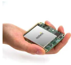
The Applanix APX-15 UAV (Figure 2) is a recent example of a GNSS-Aided Inertial solution that uses the next generation of GNSS chipsets and MEMs inertial sensors integrated together onto a small, low powered single board. Weighing at only 60 grams, it is light enough to add to even the smallest of UAVs without degrading endurance.
Figure 2: Applanix APX-15 UAV Single Board GNSS-Aided Inertial solution for Direct Georeferencing on UAVs
The APX-15 UAV produces a real-time GNSS-Aided Inertial position and orientation solution and includes the POSPac UAV post-processing software for producing a high-accuracy post-processed centimeter level differential GNSS-Aided Inertial solution for georeferencing.
1.3.3 Digital Cameras
Low cost, small, high-performance digital cameras with excellent image quality and interior stability suitable for UAV platforms are now available. These include consumer dSLR cameras such as the Nikon D800, Sony a7R and professional series of cameras from Phase One.
Using these cameras and the APX-15 UAV, Applanix has created a Direct Mapping Solution for UAVs (DMS-UAV) ready for OEM systems integrators.
2. APPLICATION EXAMPLES
Applanix’ DMS-UAV direct georeferencing technology is used on a variety of unmanned airborne platforms, both fixed-wing and rotary. The flight characteristics – endurance, altitude, speed, manoeuvrability and ability to fly beyond-line-of-sight– of different aircraft types lend themselves to particular tasks, for which there are differing rationales for direct georeferencing capability.
2.1 Fixed Wing UAVs
In the fixed-wing category, various instances of DMS-UAV have been integrated into test programs and/or commercial applications by airframe manufacturers including American Aerospace, Brican, Delair-Tech, and Trimble. Fixed-wing platforms that have flown Applanix’ position and orientation solutions vary in size from the Trimble UX5 at the small end, through Delair Tech’s DT-18 and DT-26X, and Brican’s TD -100, to American Aerospace’s RS-16 long-range platform. Typical tasks for these craft range from medium to large area surveys for volumetric calculations or earthworks monitoring, to pipeline surveys, corridor mapping tasks for transport or utility infrastructure, to long-range tasks in inhospitable terrain such as wildlife monitoring or sea-ice characterization. Short-range missions can be flown as remote-piloted or fully autonomous tasks, wholly within the operator’s line-of-sight; but for the larger, long-endurance craft missions might last for tens of hours and cover hundreds of linear miles, so are restricted to territories where regulations permit beyond-line-of-sight operations.
2.2 Vertical Take-off and Landing (VTOL) UAV’s
Rotary-winged (also known as multi-copter or VTOL – Vertical Take-off & Landing) UAVs tend to be optimized for shorter flight times, operation at lower altitudes and small area surveys. Applanix has collaborated extensively with manufacturers including Airgon, Microdrones and Yellowscan on integrating direct georeferencing capabilities into VTOL platforms. Their ability to manoeuvre in tight spaces, and to rotate while hovering in place, delivers some phenomenal advantages as platforms for survey and mapping tasks, but these abilities also present a unique set of challenges for a GNSS-Inertial system, due to the unique dynamics of the airframe. Typical survey tasks for rotary UAVs include crop analysis in high-value precision agriculture, façade scanning of historic buildings, volumetric analysis in mining and civil engineering for small sites, and accident reconstruction missions for law enforcement agencies.
3. PERFORMANCE TEST RESULTS
3.1 Test Overview
On July 22 2015, Avyon and Applanix conducted a series of test flights with the Microdrones md4-1000 quadcopter, equipped with Sony a7R camera with a 50 millimeter AF-S Nikkor f/1.8 lens, and rigidly mounted to an APX-15 GNSS Inertial system (Figure 3). The timing of the Sony a7R sensor was previously characterized and calibrated to ensure that the imagery is accurately time stamped at the mid-exposure pulse of the camera.
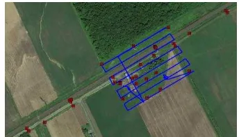
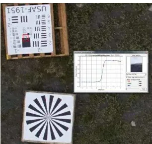
The test area consisted of a rectangular block, approximately 300 x 250 meters in size. A network of approximately 40 Ground Control Points was established within the test area, and surveyed (Figure 4). Additionally a USAF 1951 resolution target (Figure 5) and Siemens star were placed in the test area to evaluate effects of vibration on resolution. The test flight was conducted with 8 flight lines in the North-East to South-West direction (adjacent lines flown in opposite directions), and one perpendicular cross line. The end lap was ~60% while the side lap was ~40%. The flying altitude was 80 meters above ground level resulting in a GSD of ~7.8 millimeters. The average flying
speed during the flight lines was about 4.5 meters per second or 16 kilometres per hour. A GNSS base station was established within the test area, and the raw data logged for the duration of the campaign.
Flight plans were created and uploaded into the UAV’s flight management system. After manual take-off, the UAV was switched into automatic waypoint mode, following which it proceeded to fly the survey lines autonomously.
The captured images and APX-15 UAV raw sensor data was subsequently downloaded from the payload sensor for processing and analysis.
Figure 3: Microdrones md4-1000 VTOL UAV with APX-15 UAV and dSLR camera
Figure 4: Ground Control Point Distribution viewed in Google Maps
Figure 5: USAF 1951 resolution target
3.2 Processing Methodology
The GNSS-Inertial data collected by the APX-15 UAV was post-processed in POSPac UAV Single Base mode, using a base station within the project area (Figure 6). The position of this base station was precisely determined by processing a long 12 hour static observation session with the CSRS-PPP service provided by Natural Resources Canada.
Figure 6: APX-15 UAV trajectory with photo centres
The camera and lens were previously terrestrially calibrated using Applanix’ in-house camera calibration facility for approximate focal length, principal points and lens distortion parameters.
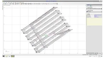
The mission data was processed through the Applanix’ Calibration and Quality Control application (CalQC) - bundle adjustment software. First, tie points were extracted using the a-priori exterior orientation (EO) from POSPac UAV and the approximate camera interior orientation from the terrestrial calibration. The tie-points and a-priori EO were then run in a bundle adjustment where the IMU-camera misalignment (boresight) angles were estimated and the focal length and principal point offsets refined from their approximate values. Lens distortions parameters were held fixed. A single 3-dimensional control point was used as part of the bundle adjustment (Figure 7) to perform quality control on the datum and focal length. The refined EO from the adjustment process was then used to generate the final map products. The total time to perform the POSPac UAV and CalQC processing was less than one hour for the complete 100 image block.
Figure 7: CalQC bundle adjustment project
3.3 Accuracy Assessment
A map view of the ortho-rectified imagery is shown in Figure 8. A sample zoomed in section of the ortho-rectified imagery is shown in Figure 9.
Figure 8: Orthophotos Displayed in Global Mapper software
Figure 9: Sample zoomed in orthophoto displayed in Global Mapper software
3.3.1 Ortho-image Accuracy
The Inpho photogrammetric software package was used to develop ortho-images from the Sony a7R imagery. The photos were ingested into an Inpho project, with updated focal length, principal point offsets and Exterior Orientation parameters resulting from the bundle adjustment.
First, a Digital Surface Model (DSM) was extracted using Inpho MATCH-T DSM version 6.0. Using this DSM, the raw images were then ortho-rectified at a GSD of 1 cm using Inpho OrthoMaster 6.0.
Ortho-image accuracy was evaluated by comparing checkpoint positions in the orthophotos with their surveyed positions. The position of each checkpoint was measured in all available images, and the results used to build per-checkpoint summary statistics. Figure 10 illustrates a typical distribution of measurements.
Figure 10: Distribution of measurements
For the block, 14 different checkpoints were visible in two or more ortho-images, resulting in a total of 56 measurements. The computed accuracy values are summarized below. A more detailed list of results is presented in Table 1 in Appendix A.
RMS Easting [m] RMS Northing [m]
RMS Total [m]
0.03 0.04 0.05
Since the GSD was 1 centimeter, this scales to pixels as follows:
RMS Easting [pixels]
RMS Northing [pixels]
RMS Total [pixels]
3.0 4.0 5.0
3.3.2 Stereo Accuracy
Stereo accuracy was assessed using CalQC software. This application has a ‘Model QC’ option that computes the estimated ground coordinates of each control point from each stereo-model, and then compares these estimated coordinates with the surveyed control point coordinates.
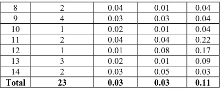
From the Model QC output, summary statistics were gathered for each checkpoint and were used to compile the overall accuracy values listed below. A more detailed list of results is provided in Table 2 in Appendix A.
RMS Easting [m] RMS Northing [m]
RMS Height [m]
0.03 0.03 0.11
The height values are higher than those for Easting and Northing, but this is expected. Given the flying height and baseline distance between exposure stations, the convergence angle between stereo pairs is only about 12 degrees.
3.3.3 Edge Response Test
A USAF 1951 target was used to perform a Normalized Edge Response Test on the Sony a7R imagery using Applanix’ Edge Response Tool (Figure 11). For a classic Bayar array pattern,
Figure 11: Normalized Edge Response Test
4. CONCLUSIONS
Direct Georeferencing allows the generation of accurate map products from airborne imagery with a single GCP and with minimal overlap and sidelap; it also reduces the processing time required to create map products compared to traditional aerial triangulation techniques thereby increasing productivity. The test outlined in this paper demonstrates the feasibility of using an Applanix APX-15 UAV system with a prosumer camera such as the Sony a7R sensor on the Microdrones md4-1000 to generate highly efficient, accurate and cost effective Directly Georeferenced map products. The accuracies achieved from this flight test were 5 centimeter RMS horizontal for the ortho products, and 3 centimeter RMS horizontal and 11 centimeter RMS vertical for stereo products, using a single GCP, image endlap and sidelap of 60% and 40% respectively, and one cross strip.
5. FUTURE WORK
Further analysis and additional flight tests will be done to investigate the effect of refining additional camera interior orientation parameters in the relative bundle adjustment such as lens distortion, as well as eliminating the cross strip.
ACKNOWLEDGEMENTS
We would like to acknowledge the efforts of Joe Kosofsky of Applanix Corporation for assisting in performing the edge response analysis. We would also like to thank Michael Hogan of Avyon in organizing and facilitating the flight campaign. Attainable Accuracy? Proceedings ASPRS Annual Meeting, St. Louis, MO USA.
Hutton J., Mostafa M.M.R., 2005. 10 Years of Direct Georeferencing for Airborne Photogrammetry, Proceedings Photogrammetric Week, Stuttgart, Germany.
Ip A.W.L, El-Sheimy N., Hutton J., 2004. Performance Analysis of Integrated Sensor Orientation, International Archives of Photogrammetry and Remote Sensing, Istanbul, Turkey, ISPRS Comm. V, Vol. XXXV, Part B5, pp. 797-802.
APPENDIX A
8 2 0.04 0.01 0.04
9 4 0.03 0.03 0.04
10 1 0.02 0.01 0.04
11 2 0.04 0.04 0.22
12 1 0.01 0.08 0.17
13 3 0.02 0.01 0.09
14 2 0.03 0.05 0.03
Total 23 0.03 0.03 0.11
Table 2: Stereo accuracy measurements